Downloaded 10 times


![1.2 Traditional surface treatments 5
Electropolishing
This technique that we will discuss in this report provides smooth surfaces with lower
roughness and higher Eacc. Surface smoothness is believed to be the origin of the cavity
performance. But that question is not totally elucidated.
The electrolyte that is used is composed of hydrouoric (40 w%) and sulfuric (96 w%)
acids in a ratio: 1 volume HF for 9 volumes of H2SO4. The bath temperature is controlled
in order to stabilize at about 30 ±C leading current densities between 30 and 100 mAcm¡2.
The cathode is made of aluminum.
Niobium oxidation during electropolishing might be written:
² 2Nb + 5SO2¡
4 + 5H2O ! Nb2O5 + 10H+ + 5SO2¡
4 + 10e¡
The reduction process is hydrogen formation at the aluminum cathode:
² 2H+ + 2e¡ ! H2
For a global and easier understanding, the oxido-reduction equation might be written:
² 2Nb + 5H2O ! 5H2 + Nb2O5
Nb2O5 is then dissolved to form niobium uoride, oxouoride species and uorosulfate or
oxysulfate and pyrosulfuryuoride because of sulfuric acid considered as hydrated sulfur
trioxide (SO3, H2O):
² NbF5 + 2(SO3, H2O) ! NbF3(SO3F)2, 2H2O
² 2NbF5 + 14SO3 ! Nb2O(SO4)4 + S2O5F2
1.2.2 Helium Processing
In this method [1] helium gas at low pressure (10¡5 torr, or just below discharge
threshold) is admitted into a cold superconducting cavity. The cavity is operated near the
maximum possible eld level for several hours. There are some indication of eld emission
reduction. In high frequency ( 1000 MHz) cavities, performance improvement occurs dur-ing
the rst few minutes. In low frequency cavities, gains continue over periods between 1
and 50 hours.
As an example, the results on a series of 1-cell 1.5 GHz cavities showed a gain of about
30% at Epk = 20-30 MV/m (that decreased to 10% at 50-60 MV/m) [1].
Helium processing was also found to be eective in suppressing eld emission from an
emitter source introduced intentionally: carbon akes deliberately placed on the super-conducting
cavity surface. This studies have clearly established the usefulness of helium
processing.
Experiments show that helium processing works in a number of dierent ways, or per-haps
in a combination of ways. It has been established that at least part of the benet
comes from removal of gas condensates. Emitters activated by deliberately condensing](https://image.slidesharecdn.com/tesimasterdeambrosis-141128040749-conversion-gate01/85/Tesi-master-Silvia-Deambrosis-9-320.jpg)
![6 Production and processing of resonant cavities: an innovative solution
gas were identied by thermometry and subsequently removed by helium processing. One
expects that condensate changes would be realized by helium ion bombardment and in a
short period of time (minutes). Another result showed that admission of helium triggers a
microdischarge at a eld emission site. If the eld level is not high enough for rf processing,
the presence f helium gas will help to initiate the discharge which subsequently destroys
the emitter. We expect that this eect should proceed quickly, probably immediately after
admitting sucient helium gas into the cavity.
Helium processing over time periods of many tents of hours is also known to reduce eld
emission. This eect has traditionally been interpreted as sputtering of the bulk emitter
over longer periods of time. Long time helium processing is more eective for low frequency
cavities because of the higher impact energy of the helium ions and the higher sputtering
rate.
Another mechanism has been suggested for the eectiveness of helium processing. In
a series of studies on dc eld emission from copper surfaces, room temperature, high volt-age
conditioning experiments have been carried out in the presence of a variety of gases,
including helium. The results of these studies have been interpreted as ion implantation
that alters the emitter properties [1].
1.2.3 Heat treatment of niobium cavities
The inuence of high temperature annealing in the nal stage of rf cavity surface
preparation has been studied [1]. Heat treatment to eliminate eld emission should not be
confused with heat treatment for postpurication, where the rf surface and the exterior of
a niobium cavity are surrounded by titanium as the solid state gettering agents and where
the rf surface is etched after HT to remove the evaporated layer.
For the superconducting cavities, the most signicant reduction in eld emission was
observed for 4 to 8 hours heat treatments at 1400-1500±C. A corroboration of the benet of
HT comes from the temperature maps: many strong emitters are seen when the standard
chemical treatment is used, whereas the HT surfaces are virtually free of emitters at 30
MV/m.
The potential benets of a new treatment indicated by sample tests or single cell cavity
tests, must always be checked on a large area, multicell cavity: the mixed experience with
HT on multicell cavities indicates that it is indeed dicult to keep large area multi cell
cavities clean on a reproducible basis.
1.2.4 High pressure rinsing
Field emitter studies [1] shows that increased vigilance in cleanliness during nal surface
preparation and assembly procedures is important to keep particulate contaminations and
associated emission under control [2, 3, 4].
A technique to improve cleanliness that is high pressure water rinsing (HPR): a jet of](https://image.slidesharecdn.com/tesimasterdeambrosis-141128040749-conversion-gate01/85/Tesi-master-Silvia-Deambrosis-10-320.jpg)
![1.3 A new chance: atmospheric plasma cleaning 7
ultrapure water is used to dislodge surface contaminants resistant to conventional rinsing
procedures.
The benets of HPR in reducing eld emission are well demonstrated.
1.2.5 High power pulsed rf processing
While the supercleanliness approach of HPR has unarguable potential, but a single
eld emission site can degrade the Q0 of a superconducting cavity , if the emitter will not
process away at the maximum rf power available. in large area structures there is always a
signicant probability that a few emitters will nd their way onto the cavity surface. This
is the reason why the maximum achievable eld decreases with the cavity area. There is
also the danger of dust falling into the cavity during installation of power coupling devices.
Therefore a technique that eliminates emitters in situ is highly desirable for successful
application of superconducting cavities to accelerators. Such a technique has been devel-oped
and it is called High Pulsed Power processing (HPP) [5, 6].
The essential idea of high power rf processing an emission site is to rise the surface elec-tric
eld at the emitter as high as possible, eve for e very short time (¿ ¹s). As the eld
rise, the emission current rises exponentially to the level at which melting, evaporation,
gas evolution, plasma formation and a microdischarge take place. the ensuing explosive
event destroys the emitter.
1.3 A new chance: atmospheric plasma cleaning
As already mentioned, preparation of cavity walls has been one of the major problems
in superconducting radio-frequency (SRF) accelerator technology. Accelerator performance
depends directly on the physical and chemical characteristics at the SRF cavity surface.
The ambitious objective of this project is to start studying a cavity surface preparation
process which is superior in terms of cost, performance, and safety, to the wet chemical
process currently in use. Plasma based processes provide an excellent opportunity to
achieve these goals.
A large number of important industrial plasma applications are carried out close to
atmospheric pressure, in many cases in atmospheric air.
The fascinating possibility to perform cleaning and/or etching processes of RF cavities
without the need of any vacuum pumping system has to be deeply explored realizing
dierent atmospheric congurations as corona plasma, rf resonance plasma, plasma jet
and torch.
We decided to start the investigation from the rf resonance plasma: it is simple, reliable
and easy to set up. It becomes possible to:
² Clean the Nb surface from carbon contamination or adsorbed gases
² Etch the Nb surface using plasma activated chemicals
² Add an ecient cleaning step to the surface treatments of cavities](https://image.slidesharecdn.com/tesimasterdeambrosis-141128040749-conversion-gate01/85/Tesi-master-Silvia-Deambrosis-11-320.jpg)

![9
Chapter 2
Industrial atmospheric plasma
treatments
This chapter attempts to give an overview of atmospheric plasma sources and their
applications. In a rst part the main scientic background concerning plasmas will be
introduced while the second part focuses on the various applications of the atmospheric
plasma technologies, mainly in the eld of surface treatments [7].
2.1 Introduction
Plasma is a more or less ionized gas. It is the fourth state of matter and constitutes
more than 99% of the universe. It consists of electrons, ions and neutrals which are in
fundamental and excited states. From a macroscopic point of view, plasma is electrically
neutral. However, it contains free charge carriers and is electrically conductive.
A plasma is created by applying energy to a gas in order to reorganize the electronic
structure of the species (atoms, molecules) and to produce excited species and ions. This
energy can be thermal, or carried by either an electric current or electromagnetic radiations.
The atmospheric plasmas described in this paper are generated from electrical energy.
The electric eld transmits energy to the gas electrons (which are the most mobile charged
species). This electronic energy is then transmitted to the neutral species by collisions.
These collisions follow probabilistic laws and can be divided in:
² Elastic collisions: they do not change the internal energy of the neutral species but
slightly rise their kinetic energy.
² Inelastic collisions: when electronic energy is high enough, the collisions modify the
electronic structure of the neutral species. It results in the creation of excited species
or ions if the collisions are energetic enough.
Most of the excited species have a very short lifetime and they get to ground state by emit-ting
a photon. The metastable species are also excited states but with a long lifetime
because their decay by emission of radiation is hampered as there are no allowed transitions](https://image.slidesharecdn.com/tesimasterdeambrosis-141128040749-conversion-gate01/85/Tesi-master-Silvia-Deambrosis-13-320.jpg)
![10 Industrial atmospheric plasma treatments
departing from the respective state: decay can only take place by energy transfers through
collisions.
2.1.1 Plasmas classication
Depending on the type of energy supply and the amounts of energy transferred to the
plasma, the properties of the plasma change, in terms of electronic density or tempera-ture.
These two parameters distinguish plasmas into dierent categories. The atmospheric
plasma sources described here are supposed to be positioned near the glow discharges and
the arcs.
In this classication, a distinction can be made between:
² Local thermodynamic (or thermal) equilibrium plasmas (LTE).
² Non-local thermodynamic equilibrium plasmas (non-LTE).
LTE plasmas
LTE plasma requires that transitions and chemical reactions are governed by collisions and
not by radiative processes.
Moreover, collision phenomena have to be micro-reversible. It means that each kind of
collision must be balanced by its inverse (excitation/deexcitation; ionization/recombination;
kinetic balance).
Moreover LTE requires that local gradients of plasma properties (temperature, density,
thermal conductivity) are low enough to let a particle in the plasma reach the equilibrium:
diusion time must be similar or higher than the time the particle need to reach the equi-librium
[5]. For LTE plasma, the heavy particles temperature is closed to the electrons
temperature (ex: fusion plasmas).
According to the Griem criterion [6], an optically thin homogeneous plasma is LTE if
the electron density fullls:
ne = 9 ¢ 1023
³ E21
EH+
´3³ kT
EH+
´
(m¡3) (2.1)
where
² E21 represents the energy gap between the ground state and the rst excited level.
² EH+=13.58 eV is the ionization energy of the hydrogen atom.
² T is the plasma temperature.
This criterion shows the strong link that exists between the required electron density for
LTE and the energy of the rst excited state.
Those rules for LTE are very strict. Thus most of the plasmas deviate from LTE,](https://image.slidesharecdn.com/tesimasterdeambrosis-141128040749-conversion-gate01/85/Tesi-master-Silvia-Deambrosis-14-320.jpg)
![2.1 Introduction 11
especially all types of low density plasma in laboratories.
Non-LTE plasmas
Departure from Boltzmann distribution for the density of excited atoms can explain the
deviation from LTE. Indeed, for low-lying levels, the electron-induced de-excitation rate of
the atom is generally lower than the corresponding electron-induced excitation rate because
of a signicant radiative de-excitation rate. Another deviation from LTE is induced
by the mass dierence between electrons and heavy particles. Electrons move very fast
whereas heavy particles can be considered static: electrons are thus likely to govern colli-sions
and transitions phenomena. Deviations from LTE are also due to strong gradients in
the plasma and the associated diusion eects.
It has been shown that the LTE distribution can be partial. For example, LTE can be
veried for the levels close to ionization threshold [7] (e.g., 5p levels and higher, in argon
plasma): such plasmas are pLTE (partial LTE).
The non-LTE plasmas can be described by a two temperature model: an electron tem-perature
(Te) and a heavy particle temperature (Th). Regarding the huge mass dierence
between electrons and heavy particles, the plasma temperature (or gas temperature) is xed
by Th. The higher the departure from LTE, the higher the dierence between Te and Th is.
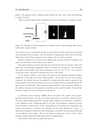
Atmospheric pressure plasmas
Figure 2.1 shows the inuence of the pressure on the transition from a glow discharge
Figure 2.1: Evolution of the plasma temperature (electrons and heavy particles) with the pressure
in a mercury plasma arc.
(TeTh) to an arc discharge. Low pressure plasmas (104 to 102 kPa) are non-LTE. Heavy
particles temperature is lower than the electronic one. The inelastic collisions between
electrons and heavy particles are excitative or ionizing. These collisions do not rise the](https://image.slidesharecdn.com/tesimasterdeambrosis-141128040749-conversion-gate01/85/Tesi-master-Silvia-Deambrosis-15-320.jpg)
![12 Industrial atmospheric plasma treatments
heavy particles temperature.
When the pressure becomes higher, collisions intensify. They induce both plasma
chemistry (by inelastic collisions) and heavy particles heating (by elastic collisions). The
dierence between Te and Th is reduced: plasma state becomes closer to LTE but does
not reach it. The signicant gradient of properties in plasma restricts a particle, moving
in the discharge, achieving equilibrium.
The density of the feeding power inuences a lot the plasma state (LTE or not). On
the whole, a high power density induces LTE plasmas (e.g. arc plasmas) whereas non-LTE
plasmas are favored by either a low density of feeding power or a pulsed power supply. In
this latter case, the short pulse duration prevents the equilibrium state from establishing.
Finally, it is important to note that an atmospheric plasma jet can be divided in two
zones:
² a central zone or plasma core which is LTE.
² a peripheral zone which is non-LTE. In this plume, heavy particles temperature is
much lower than electrons one.
Indeed, for a free-burning argon arc [6], operating conditions (a pressure of 300 kPa, cur-rents
of 300 to 400 A) are necessary to reach a LTE state in the central portion. These
conditions lead to an electron density of 1024 m¡3 in the center. Departures from LTE
occur in the outer regions of such arcs where the electron density decreases below 1024
m¡3.
Thus, the local thermodynamic equilibrium is a primordial notion since it induces the
temperature of the plasma. It strongly depends on the kind of plasma source and is deter-mining
for its applications.
2.1.2 Overview of various atmospheric plasma sources
The excitation frequency is important since it inuences the behavior of the electrons
and the ions.
The atmospheric plasma sources can be classied regarding their excitation mode.
Three groups are then highlighted:
² the DC (direct current) and low frequency discharges;
² the plasmas which are ignited by radio frequency waves;
² the microwave discharges.
Examples of various atmospheric plasma sources
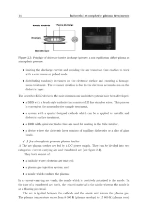
X Corona discharge [7] is a non-LTE discharge with low current density. The device
consists of a cathode-wire and an anode (the treated material), the DC power supply is](https://image.slidesharecdn.com/tesimasterdeambrosis-141128040749-conversion-gate01/85/Tesi-master-Silvia-Deambrosis-16-320.jpg)
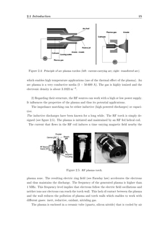
![16 Industrial atmospheric plasma treatments
or water, depending on the working power. The inductive torches work in a wide power
range: 20 kW - 1000 kW, with a gas ow rate of 10 - 200 slm. A higher working power is
accompanied with lower torch diameter and lower plasma frequency.
3) The cold plasma torch lies between the DBD and APPJ structures. The device is
shown in gure 2.6 and its properties are. The RF electrode is a stainless-steel needle. A
quartz tubing is inserted between the cathode and anode to ensure both plasma stability
and homogeneity. The plasma gas ows into the gap between the cathode and the dielectric
tube.
Figure 2.6: Left: cold plasma torch design. Right: barrier torch design.
4) A barrier torch (gure 2.6) which is similar to the RF pencil was also developed
in Czech Republic by Hubie'ka et al. (Academy of Sciences, Prague). A quartz tube is
inserted into the RF hollow electrode. The working gas is injected inside the dielectric
tube. The dielectric layer stabilizes the discharge and limits the electrode heating. The
discharge remains stable in the case of a multi-nozzle torch-barrier device. A larger surface
zone can be treated.
X The atmospheric pressure plasma jet (APPJ) is a small (L 20 cm) RF plasma torch
that works at low power. It was developed by J.Y. Jeong et al. (University of Califor-nia,
Los Angeles) in collaboration with J. Park et al. (Los Alamos National Laboratory [7]).
This system (see Fig. 16) consists of two concentric electrodes through which the work-ing
gas ows. By applying RF power to the inner electrode at a voltage between 100 and
150 V, the gas discharge is ignited. The ionized gas exits through a nozzle since the gas
velocity is about 12 m s¡1. The low injected power enables the torch to produce a stable
discharge and avoids the arc transition.
The same research team designed a rectangular version of the APPJ. This source pro-duces
a volumetric and homogeneous discharge in a 1.6 mm wide gap between two planar](https://image.slidesharecdn.com/tesimasterdeambrosis-141128040749-conversion-gate01/85/Tesi-master-Silvia-Deambrosis-20-320.jpg)
![2.2 Examples of industrial applications 17
Figure 2.7: APPJ design.
aluminum electrodes. Both electrodes are perforated to let the plasma gas ow through
them. The upper electrode is connected to the RF power supply while the lower electrode
is grounded. It has been recently applied to the deposition of hydrogenated amorphous
silicon with silane added downstream of the hydrogen-helium plasma.
2.2 Examples of industrial applications
2.2.1 Textile
In light of the disadvantages of low-pressure plasma systems, there has been increasing
interest in atmospheric pressure plasma systems and applications in the textile industry
[8]. The only available atmospheric pressure plasmas for textile industrial applications are
glow discharge systems.
The three main glow discharges at atmospheric pressure are corona, dielectric barrier
discharges (DBD) and atmospheric pressure glow discharge (APGD).
By accelerating the electric eld, the lighter particles (electrons) achieve more kinetic
energy than heavier ions and neutral gas particles. High-energy electrons induce colli-sions
and release their kinetic energies to the surroundings, and then the plasma system
reaches thermal equilibrium. In order to avoid thermal relaxation at atmospheric pressure,
a largely inhomogeneous electric eld is required. When sucient voltages are supplied to
accelerate electrons in the inhomogeneous electric eld on one of the electrodes, a sharp
needlepoint, a localized plasma (corona discharge) can be generated. An alternative way
to prevent thermal relaxation at atmospheric pressure is to introduce a changing current
frequency into a discharge. At low and high frequency, a discharge is initiated each time
between the parallel electrodes. This discharge, found in DBD, could be generated under
atmospheric pressure but would not remain uniform on the whole electrode area. Very
narrow laments are seen between electrodes in DBD.](https://image.slidesharecdn.com/tesimasterdeambrosis-141128040749-conversion-gate01/85/Tesi-master-Silvia-Deambrosis-21-320.jpg)
![18 Industrial atmospheric plasma treatments
Corona Systems for Textile Applications
Corona systems have been studied for availability in the textile industry because they
can be operated in atmospheric pressure. Although many corona systems are utilized for
continuous processing for mass production with high speed, some examples are presented
in this paper. One of the early studies discussed is the improvement of shrink resistance for
wool and mohair top. These results were obtained by using a continuous corona system,
which was able to pass through substrates between parallel Pyrex electrodes as shown
in Figure 4. This pilot scale corona device was available to not only make high-speed
production of wool and mohair top, but also improve shrink-resistance and spinnability.
For another example, Abbot [9] showed the enhancement of cotton sliver cohesiveness
Figure 2.8: A schematic diagram of continuous corona discharge system for wool and mohair.
using the corona systems with a cotton sliver passing between the large and small corona
rollers. Softal Electronic GmbH (Hamburg, Germany) [10] developed a continuous corona
system for lm surface modication. This system was designed for the roll-to-roll process,
applying to adhesion, coating, printability and deposition. Sherman Treaters Co. (Oxon,
UK) [8] designed a continuous corona system for surface modication of polypropylene
tow following melting spinning process (gure 2.9). These results showed improvement of
antistatic, friction and wettability of the treated bers, and could reduce the quantity of
spinning nish added resulting in cost-saving, environmental issues and ber performance.
Atmospheric Pressure Glow Discharge (APGD) for Textile Applications
The foundation of a stable and homogeneous plasma under atmospheric pressure was
reported in 1998 [11]. This stable and homogeneous discharge required the following con-ditions:
1) Helium was used as dilute gas,
2) Heat resistance insulating plate was set on the lower electrode plate while upper
electrode was a brush style, and
3) Power supply frequencies were 3,000 Hz and Radio-frequency (13.56 MHz).](https://image.slidesharecdn.com/tesimasterdeambrosis-141128040749-conversion-gate01/85/Tesi-master-Silvia-Deambrosis-22-320.jpg)
![2.2 Examples of industrial applications 19
Figure 2.9: A schematic diagram of continuous corona system for Polypropylene Fiber Tow de-signed
by Sherman Treaters [8].
However, this discharge could be transformed into thermal plasma such as arc discharge
when strict plasma conditions were not applied. Fluorination of poly (ethylene terephtha-late)
(PET) lm was successful compared to the results in vacuum plasma using optical
emission spectroscopy. Roth and co-workers developed the one atmospheric glow discharge
plasma reactor, called one atmosphere uniform glow discharge plasma (OAUGDP), and ap-plied
plasma treatment to textile materials [12] for surface modication and sterilization
[13]. This reactor has two parallel electrodes covered by an insulating coating and can
generate uniform plasma in helium according to Kanazawa's model [11].
Another independent development of APGD was carried out at North Carolina State Uni-versity,
the parallel plate atmospheric plasma device for industry (PALADIN), designed
specically for the industrial applications [14].
Atmospheric pressure plasma systems are suitable for textile industrial applications,
which involve mass production at high speeds, because it is possible to carry out continu-ous
processing without size limitation. Recently, even though atmospheric pressure plasma
systems were developed in Japan and the United States, Dow Corning Plasma Solutions
is the only available APGD machine manufacturer for textile applications in the world. A
model of APGD, AP-100 (width 100 cm, but width of machine is variable depending on
textile process conditions), is able to generate a stable and uniform glow discharge and
leads to continuous processing at a maximum speed of 60 m/min.
Dow Corning Plasma Solutions has supplied APGD plasma systems to several pro-duction
lines in Europe. One of them, installed at Institute of Fiber and Polymer Tech-](https://image.slidesharecdn.com/tesimasterdeambrosis-141128040749-conversion-gate01/85/Tesi-master-Silvia-Deambrosis-23-320.jpg)
![20 Industrial atmospheric plasma treatments
nology Research (IFP, Sweden), is applied to adhesion enhancement of polymer coatings
(Almedahl AB, Sweden), surface modication of automobile textiles (Borgstena Textile
Sweden AB, Sweden), increasing hydrophobicity of cellulose based materials, and improve-ment
of adhesion of polymer materials (SCA Hygiene Products AB, Sweden). In German,
Kirchho GmbH and Co. has been applying APGD plasma system to anti-shrinkage n-ishing.
The same APGD system at Polisilk S.A. in Spain is being used to improve binding
properties of polypropylene-based coating. In addition, Plasma Ireland supplied another
APGD system to Scapa Group in England for printing applications.
Plasma Applications to Textile Processing
Wettability Enhancement
The wettability enhancement of polymeric surfaces can be obtained easily by plasma treat-ment
in oxygen containing gas. However, after exposure to air, the wettability is not
durable due to the ageing process. For the textile applications of wettability enhancement,
increased durability has been obtained using plasma graft polymerization techniques. The
monomers used in plasma graft polymerization for wettability enhancement are acrylic acid,
nitro compounds, 2-hydroxyethyl methacrylate (HEMA), methyl methacrylate (MMA),
acrylamide (AAm) and acrylonitrile [8].
In 1971, the rst commercial application of plasma graft polymerization for wettability
enhancement on fabrics was conducted by Bradley [15]. After surface functionalization
by argon plasma for PET fabrics, the acrylic acid monomer was introduced into vacuum
chamber leading to uniform grafting polymerization. This technique could render PET
fabrics as wettable as cotton and improve moisture retention and washing durability. In
addition, handle properties of fabrics were improved without alteration bulk properties.
Cotton fabrics treated by this technique showed better hand properties obtained.
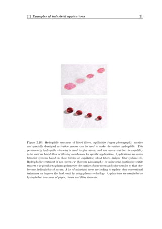
There is another and specially developed activation process that can be used to make
the surface hydrophilic (gure 2.10). This permanently hydrophilic character is used to
give woven, and non woven textiles the capability to be used as blood lter or ltering
membranes for specic applications. Applications are micro ltration systems based on
these textiles or capillaries: blood lters, dialysis lter systems etc.
Water Repellent Finishing
Fluorocarbon, hydrocarbon and mixtures of uorocarbon and hydrocarbon gases have
been used to increase hydrophobicity of polymer substrates in plasma. Compared to oxy-gen
and air plasma treatment, uorocarbon and mixtures of uorocarbon and hydrocarbon
gas plasma showed higher durability in air exposure [8].
Iriyama et al. [16] studied the water-repellency of nylon fabrics treated in uorocarbon
plasmas (CF4, C2F4, C3F6 and C6F14). The durability of water-repellency after 30 min.
washing was better in fabrics treated with saturated uorocarbon plasmas than unsatu-rated.
The saturated uorocarbon plasma introduced longer chains of polymer on fabric](https://image.slidesharecdn.com/tesimasterdeambrosis-141128040749-conversion-gate01/85/Tesi-master-Silvia-Deambrosis-24-320.jpg)
![22 Industrial atmospheric plasma treatments
surface (gure 2.10), leading to better hydrophobicity and durability. Wang et al. [17]
found similar results from plasma treatment on PET lm with mixtures of uorocarbon
and methane.
McCord et al. [18] found that the uorocarbon functional group, -CF3, played an im-portant
role in increasing water-repellency.
Anti-shrinkage Finishing
Anti-shrinkage nishing using plasma treatment is the rst successful commercialized tech-nique
for the textile industry. The rst attempt at anti-shrinkage nishing was a corona
treatment for wool fabrics [8]. Wool garments treated by corona showed better shrink re-sistance
and stability than untreated. Thorsen et al. [19] suggested that corona treatment
could be applied to mass production of wool fabric to improve shrink resistance. Compared
to corona treatment, the eciency of anti-shrinkage in plasma treatment shows better ef-fect.
Recently, low-pressure plasma and corona are available for anti-shrinkage nishing in
textile industry. Plasma treatment is considered an environmentally friendly alternative
to the conventional anti-shrinkage nishing, wool chlorination.
Regardless, further studies are still needed to apply plasma treatment to industrial
production for anti-shrinkage nishing as well as enzymatic treatment, which is another
possible environmentally friendly method for anti-shrinkage nishing.
Oxygen was known as the most eective gas for shrink proong of wool fabrics made
from plasma-treated yarns [8].
Desizing
The application of size to warp yarns before weaving plays an important role in enhance-ment
of weaving eciency due to an increase of yarn strength and reduction of yarn
hairiness. Also, it is important to remove size after weaving for further processes, dyeing
and nishing. The conventional desizing process is conducted by washing in hot water
bath.
Regardless of high temperature, complete removal of size on fabrics is impossible due to
redeposited sizes on yarns during the desizing process, resulting in poor bleaching, dyeing
and printing. Moreover, the desizing waste is a major concern of pollution world-wide,
even though a recycling technique is available.
Plasma desizing was performed as a novel technique to solve the environmental problem
of desizing [8]. The plasma desizing process consisted of two steps: gas plasma treatment
on the sized fabric and washing in solution. Compared to hydrogen peroxide desizing,
plasma treatment plus cold-water washing showed better size removal on cotton fabrics.
Oxygen plasma was more eective in desizing than either air or nitrogen. Two possible
plasma eects are involved in the plasma desizing. First one is gas vaporization of sizes by
the etching eect of plasma.
The second one is hydrophilic functionalization of size molecules, possible in conjunc-tion
with either chain scission or cross-linking. The increase in hydrophilic groups may](https://image.slidesharecdn.com/tesimasterdeambrosis-141128040749-conversion-gate01/85/Tesi-master-Silvia-Deambrosis-26-320.jpg)
![2.2 Examples of industrial applications 23
lead to higher solubility in wash solution.
Flame Retardant Finishing
Flame retardant nishing of textiles has been accomplished via plasma treatment. As
one of initial studies for ame retardant nishing on textiles, researchers studied ame
retardant nishing on natural and synthetic fabrics. The fabrics pre-absorbed with phos-phorus
and halogen containing monomers were exposed to nitrogen low-pressure plasma,
leading to graft polymerization on fabric surface. The graft polymerization by plasma with
phosphorus and halogen containing monomers improved the ame retardant properties of
fabrics.
In addition, it was proposed that plasma application of ame retardant nishing could
have economical and environmental advantages compared to conventional wet-chemical
nishing processes. For ame retardant nishing for cotton fabrics, cotton fabrics treated
by argon plasma with THPOH/NH3 and H2O2 washing were durable to 50 launderings
and launderings with chlorine bleaching.
Adhesion Enhancement
Most of composite materials, including UHMPE (ultrahigh modulus polyethylene), PPTA
(poly(p-phenylene terephthalate) and carbon bers, have excellent mechanical properties.
However, chemical inertness and smoothness of their surfaces can be a serious problem to
apply to resin matrix for composite applications. Compared to conventional wet chemical
surface modication, plasma techniques can overcome the disadvantages of high perfor-mance
bers easily and improve adhesion to resin matrix without altering physical prop-erties.
Ultrahigh-modulus polyethylene (UHMPE) bers such as Spectra. bers do not form
strong bonds with most commercially available matrix materials due to their inert chem-ical
structure. Low-pressure plasma treatments have been shown to greatly enhance the
bonding between UHMPE ber and resin matrices such as epoxy and vinyl ester resins
[20].
The plasma treatment created not only micro-roughness on the surface of UHMPE
bers, resulting in a better mechanical interlocking of the ber surface to resin matrix,
but also functional groups, leading to chemical interfacial bonding between the ber and
matrix.
Dyeability Enhancement
Dyeing in textile industry requires the development of environmentally friendly and eco-nomic
processes due to pollution and economic limitations. Plasma techniques have been
studied to replace or aid the conventional wet dyeing process. The initial approach of
plasma was corona treatment.
As an example, Wakida et al. [21] showed the possibilities of atmospheric pressure
plasma for wool fabric dyeing applications. The atmospheric pressure plasma treatment](https://image.slidesharecdn.com/tesimasterdeambrosis-141128040749-conversion-gate01/85/Tesi-master-Silvia-Deambrosis-27-320.jpg)
![24 Industrial atmospheric plasma treatments
with a mixture of helium and argon was very eective on the reduction of half-dyeing time
and an increase of dye exhaustion with acid dyes.
Sterilization
Sterilization processes are designed to destroy viable microorganisms before biomaterial
contact with living organisms. In general, either a physical or chemical process or both are
carried out sterilization. The conventional sterilization methods including heat, radiation,
and chemical treatment can terminate the microorganisms [8]. Heat treatment is an easy
method but bacteria with a pore could survive at high temperature and under some con-ditions.
Additionally, heat treatment is not acceptable to low-melting polymer materials
and it needs a relatively long period treat time. Ethylene oxide (ETO) is used as a chem-ical
treatment to sterilize many polymeric medical products. However, ETO is not only a
highly toxic gas causing cancer but easily absorbed in plastic materials. Gamma radiation
and X-ray can exterminate bacteria or viruses by breaking bonds inside the bacteria cells
and virus capsides. However, some of microorganisms resist radiation, and radiation causes
undesirable changes of substrate.
Because the power density of atmospheric plasma is not high, it does not alter the bulk
properties of substrates where bacteria and viruses live. Also, the successful design of a
remote exposure reactor can eliminate many constraints of workpiece size and shape.
Recently, the atmospheric pressure plasma has been investigated as novel sterilization
technique [13]. One of successful designs is one atmosphere uniform glow discharge plasma
(OAUGDP, University of Tennessee, Knoxville (UTK)).
Koulik et al. [22] proposed the mechanism of sterilization under atmospheric pressure
plasma as following;
1) Plasmochemical reaction: oxidation and etching,
2) Electron bombardment,
3) UV radiation,
4) Surface ablation and
5) Chemical reaction after plasma treatment.
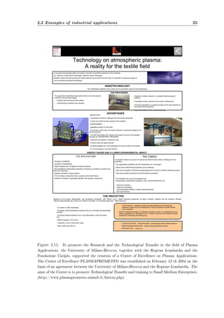
As an italian living reality the University of Milano-Bicocca, together with the Regione
Lombardia and the Fondazione Cariplo, supported the creation of a Centre of Excellence
on Plasma Applications as depicted in gure 2.11.
Mainly they work on:
² Plasma Processing for polymers, gas sterilization and VOC abatements; coating,
plasma spray, dusty plasmas;
² Plasma Processing for Energy: hydrogen production and waste treatments by plasma,
plasma Fuel Converter (PFC) for producing hydrogen rich mixtures, plasma torch
for waste treatments;
² Plasma processing for biomedical applications](https://image.slidesharecdn.com/tesimasterdeambrosis-141128040749-conversion-gate01/85/Tesi-master-Silvia-Deambrosis-28-320.jpg)
![2.2 Examples of industrial applications 27
$GYDQWDJHV
HOHFWULFDOVXUIDFHWUHDWPHQW
3ODVPD7(
$WPRVSKHULF3ODVPD7UHDWPHQW
7KHSXUSRVHRIVXUIDFHWUHDWPHQW
RISROPHUEDVHGPDWHULDOVLV
WRLQFUHDVHVXUIDFHZHWWDELOLW
WKURXJKHOHFWULFDOGLVFKDUJH7KH
ORZVXUIDFHHQHUJRISROPHU
EDVHGVXEVWUDWHVRIWHQOHDGVWR
SRRUDGKHVLRQRILQNVJOXHVDQG
FRDWLQJV7RREWDLQRSWLPXPDG
KHVLRQLWLVQHFHVVDUWRLQFUHDVH
WKHVXUIDFHHQHUJRIWKHVXE
VWUDWHWRMXVWDERYHWKDWRIWKH
PDWHULDOWREHDSSOLHG6XUIDFH
WUHDWPHQWZLWK3ODVPDUHVXOWV
LQLPSURYHGVXUIDFHDGKHVLRQ
SURSHUWLHV
3ODVPDWHFKQRORJRIIHUVLQQRYD
WLYHVROXWLRQVWRDGKHVLRQRUZHWWLQJ
SUREOHPVLQPDQLQGXVWULHV
RPSRQHQWSUHSDUDWLRQLVDQLPSRU
WDQWVWHSSULRUWRERQGLQJSDLQWLQJ
JOXLQJSULQWLQJRUFRDWLQJSURFHVVHV
3ODVPDWUHDWPHQWSURYLGHVDQHFR
QRPLFDOVROXWLRQIRUWKHHIIHFWLYHDFWL
YDWLRQRIFRPSOH[VKDSHGFRPSRQHQW
VXUIDFHVEHIRUHIXUWKHUSURFHVVLQJ
3ODVPD7(FRQIRUPVZLWK(UHJXOD
WLRQVDQGFDUULHV(PDUNLQJ
‡ 0XOWLSOH3ODVPD7UHDWLQJ+HDGV
FDQRSHUDWHIURPDVLQJOHJHQHUDWRU
‡ 7KH3ODVPD7(DQGFRQYHQWLRQDO
RURQDFDQZRUNVLPXOWDQHRXVOIURP
DVLQJOHJHQHUDWRU
‡ $QXPEHURIGLIIHUHQWQR]]OHWLSV
DUHDYDLODEOHIRUWKHHIIHFWLYHWUHDW
PHQWRIDODUJHYDULHWRIGLIIHUHQW
SDUWV
‡ 3RWHQWLDOIUHHGLVFKDUJH
‡ 6XLWDEOHIRUKLJKOLQHVSHHG
‡ 1RJHQHUDWRUDGMXVWPHQWV
QHFHVVDU
‡ (DVWRLQWHJUDWHLQWRQHZRUH[
LVWLQJSURGXFWLRQOLQHV
ZZZWDQWHFFRP
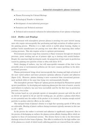
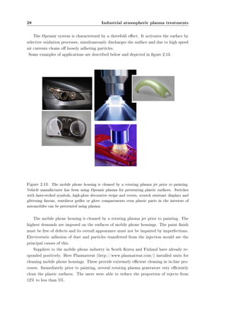
Figure 2.12: Tantec has been oering cutting-edge and environmentally-friendly Plasma and
Corona surface treatment equipment for over thirty years. Tantec develops, manufactures and
markets innovative equipment worldwide for Plasma and Corona surface treatment of plastic com-ponents.
Atmospheric Plasma treating system provides an economical solution for the cleaning and
activation of complex surfaces before further processing. Component preparation is an important
step prior to bonding, painting, varnishing and coating processes.](https://image.slidesharecdn.com/tesimasterdeambrosis-141128040749-conversion-gate01/85/Tesi-master-Silvia-Deambrosis-31-320.jpg)

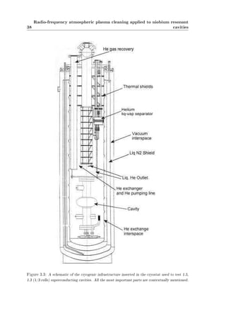
![31
Chapter 3
Radio-frequency atmospheric plasma
cleaning applied to niobium resonant
cavities
As already mentioned atmospheric pressure plasma treatment is an emerging, very ver-satile
and inexpensive technique used in various surface process such as dry etching, chem-ical
modication and surface wettability change. We decided to try to ignite a resonance
atmospheric plasma into 1.5 GHz superconducting niobium cavities to perform a feasibility
study. The second step has been the attempt to understand what really happens to the reso-nant
structure internal surface. The most powerful tool consists in the atmospheric plasma
treatment and fast rf characterization of 6 GHz small resonators.
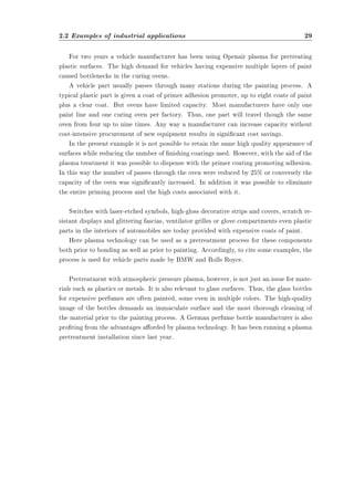
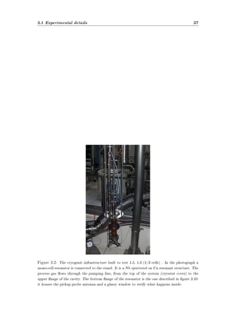
3.1 Experimental details
The experimental set up, conceived to test atmospheric plasma treatments, consists
essentially in the rf and cryogenic systems used to test the cavity quality. The only modi-
cation that has to be considered is the adding of a gas line.
3.1.1 rf apparatus
The rf apparatus we use has been already described elsewhere ([23, 24]), I just want to
give the basic information to simplify the comprehension of the following sections.
Fundamental equations for rf test
During the rf tests on cold cavities the basic rf properties such as maximum accelerating
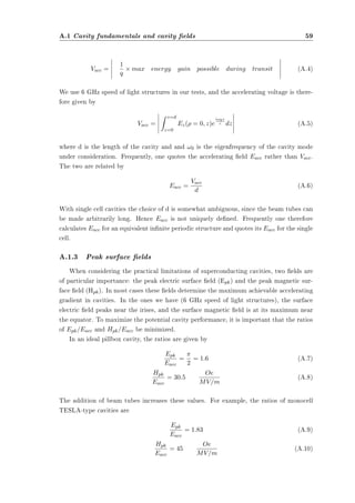
gradient (Eacc), eld emission onset, and quality factor Q0, as a function of Eacc are
determined. These tests (that have to be performed at (or near) the critical coupling) are
done inside a cryostat where the cavity is held vertically.](https://image.slidesharecdn.com/tesimasterdeambrosis-141128040749-conversion-gate01/85/Tesi-master-Silvia-Deambrosis-35-320.jpg)
![32
Radio-frequency atmospheric plasma cleaning applied to niobium resonant
cavities
The critical variable for calculating the rf parameters of a superconducting cavity is
the shunt impedance, which relates the stored energy to the eective accelerating gradient.
It (together with the resonator geometry) is the quantity necessary for calculating the
peak electric and magnetic elds for any given mode. In our case it is determined using
the electromagnetic simulation tool called Supersh [25]. All the important parameters
determined for 1.5, 1.3 and 6 GHz cavities are collected in tables 3.3 and 3.2 .
Symbol Variable name Units
r/Q Geometric shunt impedance /m
G Geometry factor
E Electric eld V/m
L Electrical lenght m
!0 cavity frequency s¡1
U Stored energy name J
Rs Surface resistance
Tc Critical temperature K
Pemit Emitted power W
R Shunt impedance
T Operational temperature K
Rres Residual surface resistance
Q0 Intrinsic quality factor
Qcpl Fundamental Power coupler coupling factor
Qpk Field probe coupling factor
RC Coupling impedance /m
Pdiss Dissipated power W
¿ Decay time s
r Shunt impedance per unit length /m
Table 3.1: Common variables when discussing rf cavities [26].
When a cavity mode oscillates with a resonant frequency !0, a stored energy U and rf
losses on the cavity walls, Pd, the quality factor can be dened as:
Q0 = !0U
Pd
(3.1)
Q0 is 2¼ times the stored energy divided by the energy consumed in one period. In the
frequency domain the Q0 can also be written as
Q0 = !0
¢!0
(3.2)
where ¢!0 is the 3-dB band width. Unfortunately, the direct measurement of the 3-dB](https://image.slidesharecdn.com/tesimasterdeambrosis-141128040749-conversion-gate01/85/Tesi-master-Silvia-Deambrosis-36-320.jpg)
![3.1 Experimental details 33
band width of a superconducting cavity is practically impossible, because it can attain
very small values as compared to the center frequency: some Hz or fractions of Hz out
of thousands of Megahertz. This is much less than the resolution of any commercially
available network or spectrum analyzer. For this reason, a time domain method must be
used.
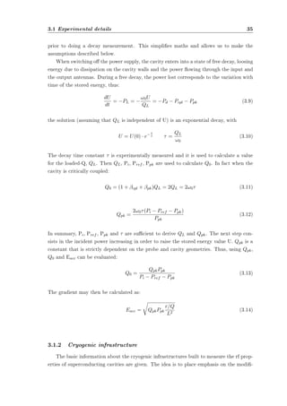
The cavity receives the rf power via an input cable and an input antenna (coupler,
gure 3.1) from a power amplier driven by a signal generator which is exactly locked onto
the resonant frequency of the cavity mode ([23, 24]).
The transmitted power is extracted from the cavity by the output antenna (pickup
Figure 3.1: Input coupler arrangement used to couple rf power into the cavity.
probe) as depicted in gure 3.1.
All antennas are connected to calibrated power meters and it is possible to calculate
the total power lost PL with the following power balance:
PL = Pd + Pcpl + Ppk (3.3)
where Pd is the power dissipated in the cavity walls, Pcpl is the power leaking back out the
fundamental power coupler and Ppk is the power transmitted out via the pick up antenna.
This equation is valid for a cavity with no driving term that has a stored energy equal to
U.
In this condition the so called Q loaded is introduced to take into account the reso-](https://image.slidesharecdn.com/tesimasterdeambrosis-141128040749-conversion-gate01/85/Tesi-master-Silvia-Deambrosis-37-320.jpg)
![34
Radio-frequency atmospheric plasma cleaning applied to niobium resonant
cavities
nant circuit behavior when it is coupled with an external line:
QL = !0U
PL
(3.4)
The quality factor, for each dissipated power, could be written as:
Q0 = !0U
Pd
Qcpl = !0U
Pcpl
Qpk = !0U
Ppk
(3.5)
Those Q values are proportional to the number of cycles the system needs to dissipate all
the energy on the considered transmission line. It's important to control if the dissipated
power in the couplers is higher or lower than the power dissipated on the cavity walls.
It follows that:
1
QL
=
1
Q0
+
1
Qcpl
+
1
Qpk
(3.6)
Each transmission line has its own external coupling factor ¯ dened by:
¯x = Q0
Qx
= Px
Pd
(x = cpl; pk) (3.7)
The transmission antenna should be sized in order to avoid perturbation of the cavity op-eration:
this condition is reached when ¯pk ¿ 1. In this way the antenna pickups the bare
minimum energy required for the measurement. Moreover it must be far enough from the
coupler antenna to avoid the signal transmission without resonance inside the cavity (no
cross-talking). On the other side, to be able to transfer all the input power to the cavity,
the coupler should satisfy the condition ¯cpl= 1. Thus it assures a perfect match between
the system and the cavity electrical impedances (coupling). In other words, when ¯cpl= 1
the input power equals the power dissipated on the cavity walls plus the small amount of
power that goes out of the pickup port:
Pd = Pi ¡ Pref ¡ Ppk (3.8)
where Pi is the incident power, Pref is the reected power and one assumes that Ppk ¿Pd.
Impedance matching is essential otherwise a mismatch causes power to be reected back
to the source from the boundary between the high impedance and the low impedance. The
reection creates a standing wave, which leads to further power waste. The impedance
matching device is the antenna tuner. When ¯ is not equal to 1 (i. e. systems with a xed
input antenna or cavities when used to accelerate beam) the determination of the stored
energy becomes more complex. More details on the calculation necessary for such cases
are given in reference [26]. Fortunately, our system allows us to achieve critical coupling](https://image.slidesharecdn.com/tesimasterdeambrosis-141128040749-conversion-gate01/85/Tesi-master-Silvia-Deambrosis-38-320.jpg)
![40
Radio-frequency atmospheric plasma cleaning applied to niobium resonant
cavities
process gas is helium it has to be properly recovered (through the Lab automatic recovery
system).
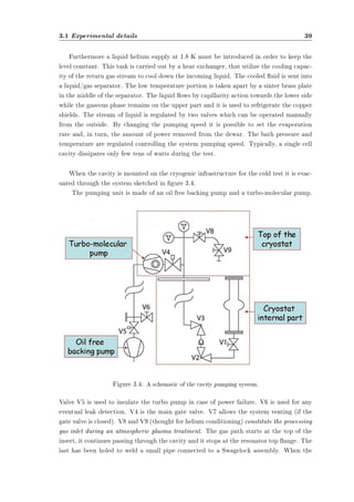
V3 allows leaving under vacuum the xed part of the system, which is connected to
the cavity by the VCR between V2 and V3.
The cryostat vacuum chamber has a long pipe connecting the pumps (at room temper-ature)
to the cavity immersed in the liquid helium. In this situation the cavity itself acts
as a cryogenic pump, while the low conductance of the pipe reduces the eective pumping
speed of the upper pumps. It is thus advisable to evacuate the cavity before the mounting
on the cryostat insert using a separated vacuum facility.
Finally, after an overnight baking and 8 hours of pumping the pressure is usually in
the 10¡9 mbar range.
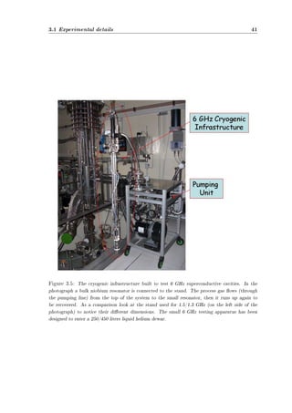
6 GHz cavities cryogenic infrastructure
The stand we use to perform the rf tests of 6 GHz cavities has been recently built [27]
and its global appearance is depicted in gure 3.5.
This insert is very compact: it has been conceived to enter a 450 or 250 l dewar neck.
Such an infrastructure permit us to signicantly reduce the cryogenic power consump-tion,
avoiding any loss during a helium transfer into a cryostat: a measurement performed
at 4.2 K requires roughly 30 liters of liquid He.
On the 6 GHz stand top ange a few holes have been properly drilled to allow a way
through for the two rf cables, the thermal probe and the vacuum line (gure 3.6).
The most important thing to notice is the all metal valve placed to permit the process gas
to ow in when necessary. All the technical details are deeply analyzed in [27]: I just want
to underline the gas path starts at the top of the insert, it continues passing through the
cavity and than it goes back to the stand upper part to be recovered.
There is a linear feedthrough (gure 3.6) that, together with the bellow connected on
the upper cavity ange, permits the coupler antenna motion. It is surrounded by a metal
structure used to x the stand to the overhead traveling crane during the needed displace-ments.
The rf cables connectors (N-type) are clearly visible too: they are embedded into
two supports, thought to avoid their stresses or motions during the cavity measurement.
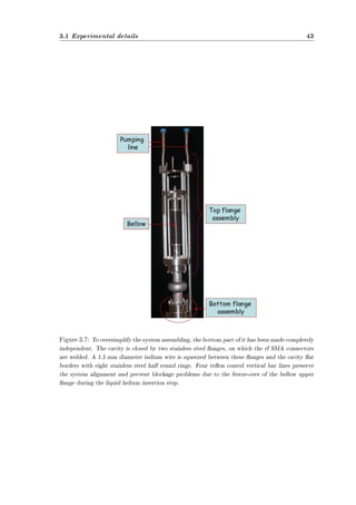
As shown in gure 3.7, to oversimplify the system assembling, the bottom part of
it has been made completely independent: the small cavity can be mounted without the
presence of the complete stand that would make the work complicated. The cavity is
closed by two stainless steel anges, on which the rf SMA connectors are welded. A 1.5
mm diameter indium wire is squeezed between these anges and the cavity at borders
with eight stainless steel half round rings.
Four teon coated vertical bar lines preserve the system alignment and prevent block-age
problems due to the freeze-over of the bellow upper ange during the liquid helium
insertion step.
The bottom part is covered by a ¹-metal shield during the rf tests.](https://image.slidesharecdn.com/tesimasterdeambrosis-141128040749-conversion-gate01/85/Tesi-master-Silvia-Deambrosis-44-320.jpg)
![42
Radio-frequency atmospheric plasma cleaning applied to niobium resonant
cavities
Figure 3.6: On the 6 GHz stand top ange a few holes have been properly drilled to allow a way
through for the two rf cables, the thermal probe and the vacuum line. The most important thing
to notice is the all metal valve placed to permit the process gas to ow in when necessary (all the
technical details are deeply analyzed in [27]). The gas ows from the top of the insert, it continues
passing through the cavity and than it goes back to the stand upper part (to be recovered).](https://image.slidesharecdn.com/tesimasterdeambrosis-141128040749-conversion-gate01/85/Tesi-master-Silvia-Deambrosis-46-320.jpg)
![44
Radio-frequency atmospheric plasma cleaning applied to niobium resonant
cavities
3.1.3 Procedure
Figure 3.8: Experimental conguration for a typical resonance atmospheric plasma treatment.
First of all a rf tested resonator is needed so that the corresponding Q vs Eacc curve
represents our starting point. As an example, a set of excitation curves of 1.5 GHz bulk
niobium resonant cavities is depicted in gure 3.9. The quality factor is higher than 1010
while the accelerating eld exceeds 30 MV/m.
The operative procedure we developed to perform the resonance atmospheric plasma
treatment of a superconducting cavity is the following:
² The rst thing to do is to get the warm critical coupling condition. Moving the
coupler antenna and changing the loop phase, it is possible to minimize the reected
power determining the ideal matching condition ([23, 24]).
² The next step consists into the gas inlet and outlet opening while maintaining the rf
power on. Usually it is necessary to set the proper matching condition again (slightly
modifying the antenna position and the loop phase).
² The third important point is the power increasing until the plasma ignition.
² Then the resonance atmospheric plasma is kept on for the decided time interval (30
minutes is a typical process duration).
² rf power is switched o while the gas ux is hold stable. The resonant cavity has to
be screwed up before closing the gas line and starting pumping again.](https://image.slidesharecdn.com/tesimasterdeambrosis-141128040749-conversion-gate01/85/Tesi-master-Silvia-Deambrosis-48-320.jpg)
![3.2 1.5 GHz cavities 45
Figure 3.9: An example of a set of excitation curves of cavities (1-cell, 1.5 GHz) of TTF (Tesla
Test Facility) production. Tests were done at 2 K [28].
² The last step is the cavity rf testing to compare the new characteristic to the previous
data.
Comments
First of all it is necessary to work at (or near) the critical coupling condition to get
the maximum electromagnetic eld into the resonator cell. Let's visualize the Q vs Eacc
curve: when the atmospheric plasma is ignited the quality value, the accelerating eld (and
obviously Ppk) decrease suddenly to prove it is consuming part of the forward power.
It is essential to avoid the Nb cleaned surface contamination due to the process gas.
Ideally it has to be extra-pure. Furthermore the gas cylinder must be connected to the
cryogenic infrastructure pipe line through electropolished stainless steal tubes. All the
used connections have to be metallic and properly airtight.
Moreover we must be careful while using rf power. All the steps of the atmospheric
plasma treatments have to be carefully monitored through an electromagnetic eld probe
[29].
3.2 1.5 GHz cavities
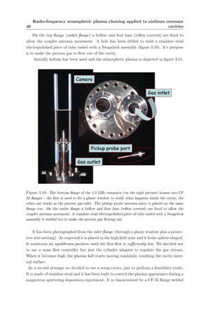
The gas inlet is on the bottom ange (inlet ange). The last is a CF 100 with two
CF 35 anges and the pickup probe entry (gure 3.10). One of the two CF 35 anges is
connected to the gas cylinder (through a proper transition) with a plastic tube. The other
has been used as a window.](https://image.slidesharecdn.com/tesimasterdeambrosis-141128040749-conversion-gate01/85/Tesi-master-Silvia-Deambrosis-49-320.jpg)
![51
Chapter 4
Discussion
Atmospheric-pressure plasma treatment is an emerging, very versatile and inexpensive
technique used in a variety of surface processes such as dry etching, surface treatments and
modication of surface wettability.
We have applied a resonance atmospheric plasma cleaning step to further clean a 6
GHz Nb seamless cavity observing an increment in the Q0 from 7 £ 106 to 2 £ 107.
We have started the investigation of a simple, reliable and easy to set up atmospheric
plasma treatment. Looking at the experimental results the most probable explanation is
that helium plasma changes the energy of the cavity internal surface. After the treatment
it becomes extremely hydrophilic.
The changing of a surface hydrophilicity/hydrophobicity (and hence water wettability)
is a mechanism widely studied in the nanotechnology eld and in material science: plasma
treatment is one of the most versatile techniques used for such surface modication. It is
also widely used to alter the surface properties of materials in a number of applications
like improving adhesion of coatings to metals and polymers [30], increasing wettability and
printability of polymers [31, 32], enhancing biocompatibility of implants [33], and in the
manufacturing of semiconductor devices [34, 35].
The increased wettability due to the plasma action on the inner cavity surface has
proved to enhance the benecial action of water rinsing pushing the Q0 value further up
close to 3 £ 107.
Water wettability
The individuation and construction of the right plasma source by which it would have been
possible and easy to treat the internal part of an accelerating cavity has been studied a bit
in this Lab and the sources, characterized by a dierent plasma power, ignition mechanism
and plasma shape, have been already described in [36].
The eect of a 5 minutes treatment on dierent substrates has been analyzed using
the sessile drop method and measuring the contact angle (C.A.) of a 300 ¹l deionized
water droplet. An increment in hydrophilicity and wettability has been evidenced by the](https://image.slidesharecdn.com/tesimasterdeambrosis-141128040749-conversion-gate01/85/Tesi-master-Silvia-Deambrosis-55-320.jpg)

![55
Chapter 5
Conclusions and future plan
More experiments will be carried on 6 GHz cavities exploring the eects of rinsing time
and helium ux variation.
The cleaning process will be also studied on 1.5/1.3 GHz cavities in order to analyze
what happens when the ratio ionization volume/cell surface decreases. It is easy to think
the plasma ball has to be maintained close enough to the surface to be treated: as already
discussed, it moves randomly when the ux ow is high. It is mandatory to understand
everything about the gas stream dynamic and to make the plasma to touch the resonator
internal surface.
Moreover it could be interesting to try to ignite a resonance atmospheric plasma into
a multi-cell cavity.
The chemical activation by atmospheric plasma gives also the possibility to add reactive
gases in the carrier ux and investigate the etching rate due to chemical activated uorine
ions coming from mixture of CF4, NF3 with and without oxygen. These gas mixtures have
already successfully been used to etch Nb in the semiconductor industry for the realization
of Josephson junctions ([37, 38]).
The following step will consist in the realization of dierent atmospheric congurations
as corona plasma, plasma jet and torch.](https://image.slidesharecdn.com/tesimasterdeambrosis-141128040749-conversion-gate01/85/Tesi-master-Silvia-Deambrosis-59-320.jpg)

![57
Appendix A
Basics of superconducting
radio-frequency cavities
In this chapter we give an overview of the basics of superconducting cavities. We start
by discussing the electrodynamics of radiofrequency (rf) cavities, the accelerating mode
and the general expressions used to describe power dissipation. Although later we focus
exclusively on superconducting cavities, this section apply equally well to both normal and
superconducting resonant structures.
In the second part we introduce the rudiments of superconductivity. In particular, we
will illustrate why superconducting cavities dissipate a small, but nite amount of power
despite the fact that superconductors carry dc currents without losses. We will also explain
the fundamental magnetic eld limitation of superconducting cavities.
This chapter is not designed to give a deep description of the theory of cavities: we will
just emphasize the aspects needed to understand this report. For further information the
reader is referred to numerous texts that give an excellent review of the subject (see, for
example [1, 39]).
A.1 Cavity fundamentals and cavity elds
A.1.1 Radio-frequency elds in cavities
The rf eld in cavities are derived from the eigenvalue equation
Ã
r2 ¡
1
c2
@2
@t2
!µ
E
H
¶
= 0 (A.1)
which is obtained by combining Maxwell's equations [40]. It is subject to the boundary
conditions
bn £ E = 0 (A.2)
and
bn ¢H = 0 (A.3)](https://image.slidesharecdn.com/tesimasterdeambrosis-141128040749-conversion-gate01/85/Tesi-master-Silvia-Deambrosis-61-320.jpg)
![58 Basics of superconducting radio-frequency cavities
Figure A.1: Schematic of a generic speed-of-light cavity. The electric eld is strongest near the
symmetric axis, while the magnetic eld is concentrated in the equator region.
at the cavity walls. Here bn is the unit normal to the rf surface, c is the speed of light and
E and H are the electric and magnetic eld respectively. In cylindrically symmetric
cavities, such as the pillbox shape, the discrete mode spectrum given by A.1 splits into
two groups, transverse magnetic (TM) modes and transverse electric (TE) modes. For TM
modes the magnetic eld is transverse to the cavity symmetry axis whereas for TE modes
it is the electric one to be transverse. For accelerating cavities, therefore, only TM modes
are useful.
Modes are classied as TMmnp, where integers m, n, and p count the number of sign
changes of Ez in the ©, %, and z directions respectively. Only TM0np (n = 1; 2; 3:::; p =
0; 1; 2:::) modes have a non vanishing longitudinal electric eld on axis, and the TM010
mode is used for acceleration in most cavities.
The typical shape of speed of light cavities [1] is shown in Figure A.1. The electric eld
of the TM010 mode is greatest at the irises and near the symmetry axis, while the magnetic
led is concentrated in the equator region. The geometry of the cell and the addition of
beam tubes make it very dicult to calculate the elds analytically, and one reverts to
numerical simulations with codes such as SUPERFISH to obtain the eld proles [25].
Although TM modes acquire a nite Hz due to the perturbative eect of the beam tubes,
the main characteristic of the TM modes are preserved, and one still uses the TMmnp
classication scheme to identify modes.
A.1.2 The accelerating eld
The accelerating voltage (Vacc) of a cavity is determined by considering the motion of
a charged particle along the beam axis. For a charge q, by denition,](https://image.slidesharecdn.com/tesimasterdeambrosis-141128040749-conversion-gate01/85/Tesi-master-Silvia-Deambrosis-62-320.jpg)
![60 Basics of superconducting radio-frequency cavities
These values were obtained by solving for the elds in the TM010 mode numerically with
the code SUPERFISH ([25], Chapter ??).
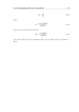
A.1.4 Power dissipation and the cavity quality
To support the electromagnetic elds, currents ow in the cavity walls at the surface.
If the walls are resistive, the currents dissipate power. The resistivity of the walls is char-acterized
by the material dependent surface resistance RS which is dened via the power
Pd dissipated per unit area:
dPd
da
=
1
2RSjH2j (A.11)
In this case, H is the local surface magnetic eld. In the next section we will show that
superconductors are not completely lossless at rf frequencies, so that the previous formula
applies equally to normal conductors and superconductors.
Directly related to the power dissipation is an important gure of merit called the cav-ity
quality (Q0). It is dened as
Q0 = !0U
Pd
(A.12)
U being the energy stored in the cavity. The Q0 is just 2¼ times the number of rf cycles it
takes to dissipate an energy equal to that stored in the cavity.
For all cavity modes, the time averaged energy in the electric eld equals that in the mag-netic
eld, so the total energy in the cavity is given by
U =
1
2¹0
Z
V
jHj2dv =
1
2²0
Z
V
jEj2dv (A.13)
where the integral is taken over the volume of the cavity. Equation A.11 yields the dissi-pated
power
Pd =
1
2
Z
S
RSjHj2ds (A.14)
where the integration is taken over the interior cavity surface. (By keeping RS in the
integral we have allowed for a variation of the surface resistance with position.) Thus one
nds for Q0:
Q0 =
R
V jHj2dv R
S RSjHj2ds (A.15)
!0¹0
The Q0 is frequently written as](https://image.slidesharecdn.com/tesimasterdeambrosis-141128040749-conversion-gate01/85/Tesi-master-Silvia-Deambrosis-64-320.jpg)


![LIST OF FIGURES 65
List of Figures
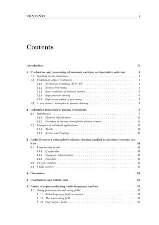
1.1 A seamless Tesla Type bulk niobium 6 GHz cavity. Spun resonators don't need
welding (even for anges). . . . . . . . . . . . . . . . . . . . . . . . . . . . . . 2
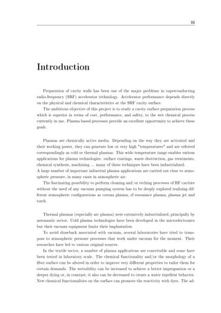
1.2 Spinning of a seamless multicell resonator from a circular blank. . . . . . . . . . . 2
2.1 Evolution of the plasma temperature (electrons and heavy particles) with the pres-sure
in a mercury plasma arc. . . . . . . . . . . . . . . . . . . . . . . . . . . . 11
2.2 Principle of a Corona discharge and a hollow needle to plate discharge (left: positive
needle, right: negative needle). . . . . . . . . . . . . . . . . . . . . . . . . . . . 13
2.3 Principle of dielectric barrier discharge (picture: a non equilibrium diuse plasma
at atmospheric pressure. . . . . . . . . . . . . . . . . . . . . . . . . . . . . . . 14
2.4 Principle of arc plasma torches (left: current-carrying arc; right: transferred arc). . 15
2.5 RF plasma torch. . . . . . . . . . . . . . . . . . . . . . . . . . . . . . . . . . . 15
2.6 Left: cold plasma torch design. Right: barrier torch design. . . . . . . . . . . . . 16
2.7 APPJ design. . . . . . . . . . . . . . . . . . . . . . . . . . . . . . . . . . . . . 17
2.8 A schematic diagram of continuous corona discharge system for wool and mohair. . 18
2.9 A schematic diagram of continuous corona system for Polypropylene Fiber Tow
designed by Sherman Treaters [8]. . . . . . . . . . . . . . . . . . . . . . . . . . 19
2.10 Hydrophilic treatment of blood lters, capillarities (upper photograph): another
and specially developed activation process can be used to make the surface hy-drophilic.
This permanently hydrophilic character is used to give woven, and non
woven textiles the capability to be used as blood lter or ltering membranes for
specic applications. Applications are micro ltration systems based on these tex-tiles
or capillaries: blood lters, dialysis lter systems etc. Hydrophobic treatment
of non woven PP (bottom photograph): by using semi-continuous textile treaters
it is possible to plasma polymerize the surface of non woven and other textiles so
that they become hydrophobic of nature. A lot of industrial users are looking to
replace their conventional techniques or improve the nal result by using plasma
technology. Applications are oleophobic or hydrophobic treatment of paper, tissues
and lter elements. . . . . . . . . . . . . . . . . . . . . . . . . . . . . . . . . . 21](https://image.slidesharecdn.com/tesimasterdeambrosis-141128040749-conversion-gate01/85/Tesi-master-Silvia-Deambrosis-69-320.jpg)
![LIST OF FIGURES 67
3.6 On the 6 GHz stand top ange a few holes have been properly drilled to allow a
way through for the two rf cables, the thermal probe and the vacuum line. The
most important thing to notice is the all metal valve placed to permit the process
gas to ow in when necessary (all the technical details are deeply analyzed in [27]).
The gas ows from the top of the insert, it continues passing through the cavity
and than it goes back to the stand upper part (to be recovered). . . . . . . . . . 42
3.7 To oversimplify the system assembling, the bottom part of it has been made com-pletely
independent. The cavity is closed by two stainless steel anges, on which
the rf SMA connectors are welded. A 1.5 mm diameter indium wire is squeezed
between these anges and the cavity at borders with eight stainless steel half
round rings. Four teon coated vertical bar lines preserve the system alignment
and prevent blockage problems due to the freeze-over of the bellow upper ange
during the liquid helium insertion step. . . . . . . . . . . . . . . . . . . . . . . 43
3.8 Experimental conguration for a typical resonance atmospheric plasma treatment. 44
3.9 An example of a set of excitation curves of cavities (1-cell, 1.5 GHz) of TTF (Tesla
Test Facility) production. Tests were done at 2 K [28]. . . . . . . . . . . . . . . 45
3.10 The bottom ange of the 1.5 GHz resonator (on the right picture) houses two CF
35 anges : the rst is used to x a glassy window to verify what happens inside
the cavity, the other one works as the process gas inlet. The pickup probe antenna
entry is placed on the same ange too. On the outlet ange a bellow and four
bars (teon covered) are xed to allow the coupler antenna movement. A stainless
steal electropolished piece of tube ended with a Swagelock assembly is welded too
to make the process gas owing out. . . . . . . . . . . . . . . . . . . . . . . . . 46
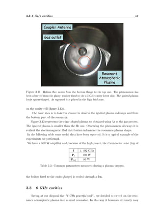
3.11 Helium ux moves from the bottom ange to the top one. The phenomenon has
been observed from the glassy window xed to the 1.5 GHz cavity lower side. The
ignited plasma looks sphere-shaped. As expected it is placed in the high eld zone. 47
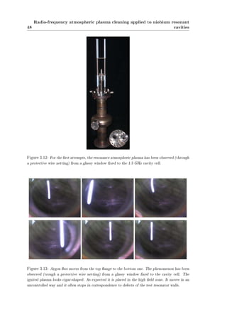
3.12 For the rst attempts, the resonance atmospheric plasma has been observed (through
a protective wire netting) from a glassy window xed to the 1.5 GHz cavity cell. . 48
3.13 Argon ux moves from the top ange to the bottom one. The phenomenon has
been observed (trough a protective wire netting) from a glassy window xed to
the cavity cell. The ignited plasma looks cigar-shaped. As expected it is placed
in the high eld zone. It moves in an uncontrolled way and it often stops in
correspondence to defects of the test resonator walls. . . . . . . . . . . . . . . . 48
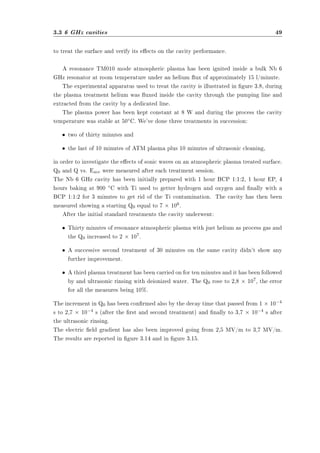
3.14 Q vs. Eacc of the Nb 6 GHz cavity treated with atmospheric resonance plasma.
± starting situation; £ 30 minutes plasma treatment; 4 60 minutes plasma
treatment. . . . . . . . . . . . . . . . . . . . . . . . . . . . . . . . . . . . . . 50
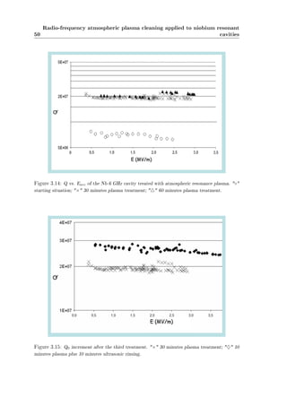
3.15 Q0 increment after the third treatment. £ 30 minutes plasma treatment; }
10 minutes plasma plus 10 minutes ultrasonic rinsing. . . . . . . . . . . . . . . . 50
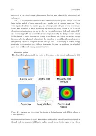
4.1 Magnetic and electric eld distribution of the fundamental mode TM010 referred
to a tesla type cavity. . . . . . . . . . . . . . . . . . . . . . . . . . . . . . . . . 52](https://image.slidesharecdn.com/tesimasterdeambrosis-141128040749-conversion-gate01/85/Tesi-master-Silvia-Deambrosis-71-320.jpg)

![BIBLIOGRAPHY 69
Bibliography
[1] H. Padamsee, J. Knoblock, H. T., RF Superconductivity for Accelerators, Wiley and
Sons, New York, 1998.
[2] P. Bernard, et al., Proceeedings of the 1992 European Particle Accelerator Conference,
edited by E.H. Henke et al. Editors Frontiers (1992) 1269.
[3] N. Pupeter, Proceedings of the 7th Workshop on RF Superconductivity, edited by B.
Bonin, Gif-sur-Yvette, France (1995) 67.
[4] K. e. a. Saito, Proceedings of the 6th workshop on RF Superconductivity, edited by
R.M. Sundelin, CEBAF, Newport News (1994) 1151.
[5] J. Graber, Nucl. Instrum. Methods Phys. Res. A (1994) 572.
[6] C. e. a. Crawford, Part. Accel. 1 (1995) 49.
[7] C. Tendero, C. Tixier, P. Tristant, J. Deasmaison, P. Leprince, Spectrochimica Acta
B 61 (2006) 230.
[8] Y. Hwuang, Characterization of atmospheric pressure plasma interactions with tex-tile/
polymer substrates, PhD Thesis, 2003.
[9] G. Abbot, G. Robinson, Textile Research Journal 47(2) (1977) 199202.
[10] S. Meiners, J. Salge, E. Prinz, F. Forster, Surface and Coatings Technology 98 (1998)
11211127.
[11] S. Kanazawa, M. Kogoma, T. Moriwaki, S. Okazaki, Journal of Physics D - Applied
Physics 21 (1988) 838840.
[12] P. Tsai, L. Wadsworth, J. Roth, Textile Research Journal 67(5) (1997) 359369.
[13] T. Montie, K. Kelly-Wintenberg, J. Roth, IEEE Transactions on Plasma Science 28(1)
(2000) 4150.
[14] C. Tendero, C. Tixier, P. Tristant, J. Deasmaison, P. Leprince, 25th IEEE-ICOPS
Paper 3B03 (1998) 178.
[15] A. Bradley, J. Fales, Chemical Technology 1(4) (1971) 232237.](https://image.slidesharecdn.com/tesimasterdeambrosis-141128040749-conversion-gate01/85/Tesi-master-Silvia-Deambrosis-73-320.jpg)
![70 BIBLIOGRAPHY
[16] Y. Iriyama, T. Yasuda, D. Cho, H. Yasuda, Journal of Applied Polymer Science 39
(1990) 249264.
[17] H. Wang, M. Rembold, J. Wang, Journal of Applied Polymer Science 49 (1993) 701
710.
[18] M. McCord, Y. Hwang, L. Canup, M. Qiu, Y. Bourham, Journal of Applied Polymer
Science.
[19] W. Thorsen, R. Landwehr, Textile Research Journal 40(8) (1970) 688695.
[20] D. Biro, G. Pleizier, Y. Deslandes, Journal of Applied Polymer Science 47 (1993)
883894.
[21] T. Wakida, S. Tokino, S. Niu, M. Lee, H. Uchiyama, M. Kaneko, Textile Research
JOurnal 63 (1993) 438442.
[22] P. Koulik, Plasma Chemistry and Plasma Processing 20 (2000) 159161.
[23] S. Deambrosis, 6 GHz cavities: a method to test A15 intermetallic compounds rf
properties, PhD Thesis, 2008.
[24] G. Lanza, New magnetron congurations for sputtering Nb thin lms into Cu tesla-type
superconducting cavities, PhD Thesis, 2008.
[25] K. Halbach, R. Holsinger, Particle Accelerators 7 (1976) 213222.
[26] T. Powers, Proceedings of the 12th workshop on RF Superconductivity, Cornell Uni-versity,
Ithaca, NY, USA 0.
[27] A. Rossi, A miniaturized 6 GHz infrastructure for cutting down the cost of RF super-conducting
research, Master Thesis, 2008.
[28] L. Lilje, Experimental Investigations on Superconducting Niobium Cavities at Highest
Radiofrequency Fields, PhD Thesis, 2001.
[29] I. C. on Non-ionizing Radation Protection, Health Physics 74 (1998) 494521.
[30] E. Liston, L. Martinu, M. Wertheimer, J. Adhesion Sci Technol. 7 (1993) 10911127.
[31] D. Briggs, Surface treatments for polyolens, in: Surface Analysis and Pretreatment
of Plastics and Metals, Applied Sciece Publishers, Essex, England, 1982.
[32] S. Wu, Modications of polymer surfaces: mechanism of wettability and bondability
improvements, in: Polymer Interface and Adhesion, Marcel Dekker, New York, 1982.
[33] P. Chu, J. Chen, L. Wang, N. Huang, Mat. Sci. Eng. 36 (2002) 143206.](https://image.slidesharecdn.com/tesimasterdeambrosis-141128040749-conversion-gate01/85/Tesi-master-Silvia-Deambrosis-74-320.jpg)
![BIBLIOGRAPHY 71
[34] H. Shmid, B. Kegel, W. Petasch, G. Liebel, Proceedings of Joint 24th International
Conference Microelectronics (MIEL) and 32nd Symposium Devcs Materials SD'96,
Nova Gorcia, Slovenia 0 (1996) 1735.
[35] L. Lieberman, A. Lichtenberg, Principles of Plasma Discharges and Material Pro-cesing,
Wiley, New York, 1994.
[36] N. Patron, R. Baracco, L. Phillips, M. Rea, C. Roncolato, D. Tonini, P. V., Proceed-ings
of the thin lms workshop pushing the limits of RFS, Legnaro, Italy 0.
[37] M. Chen, R. Wang, J. Vac. Sci. Technol. A 1.
[38] J. Sasserath, J. Vivalda, J. Vac. Sci. Technol. A 8.
[39] H. Piel, CERN Accelerator School: Superconductivity in Particle Accelerators, In S.
Turner editor, Hamburg, Germany, 1988.
[40] J. Jackson, Classical Eectrodynamics, Wiley and Sons, New York, 2nd edition, 1975.](https://image.slidesharecdn.com/tesimasterdeambrosis-141128040749-conversion-gate01/85/Tesi-master-Silvia-Deambrosis-75-320.jpg)


The document discusses innovative production and processing techniques for niobium resonant cavities used in superconducting radio-frequency (SRF) accelerator technology, highlighting the advantages of atmospheric plasma cleaning over traditional methods. It includes a detailed exploration of various surface treatments and their effectiveness in enhancing cavity performance, addressing challenges like field emission and thermal breakdown. The project aims to improve cost, performance, and safety in cavity preparation through advanced plasma-based techniques.


