Downloaded 217 times


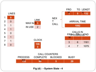


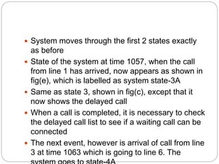


The document describes a simulation of a telephone system to track processed, completed, blocked and busy calls. It shows the system state at various time steps as calls arrive and are connected or finished. When lines are all in use, arriving calls are delayed rather than lost. The simulation runs by scanning for the next event, selecting the activity that causes it, updating records to reflect the event's effects, and gathering statistics.