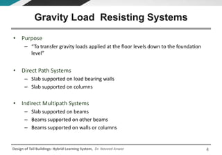
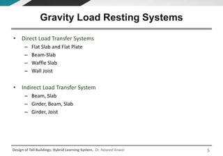
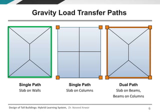
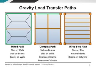
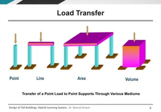
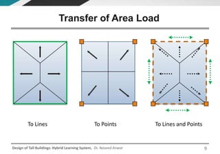
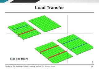
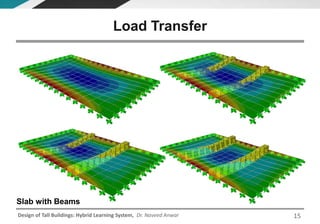
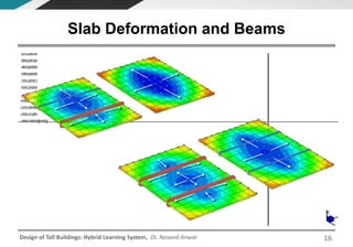
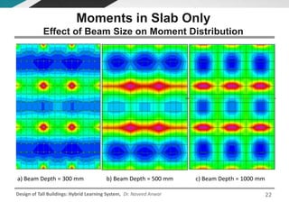
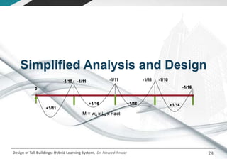
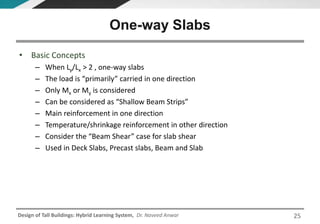
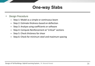
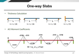
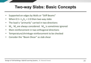
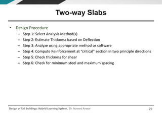
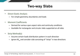
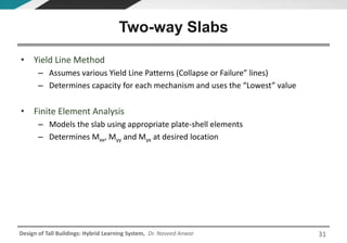
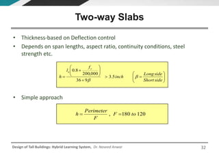
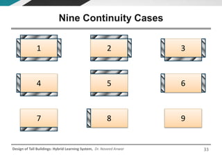
Dr. Naveed Anwar
Executive Director, AIT Consulting
Affiliated Faculty, Structural Engineering
Director, ACECOMS
Design of Tall Buildings
Hybrid Learning System
Dr. Naveed Anwar
Executive Director, AIT Consulting
Affiliated Faculty, Structural Engineering
Director, ACECOMS
Lecture 8: Structural Analysis for
Gravity Loads
Design of Tall Buildings
Design of Tall Buildings: Hybrid Learning System, Dr. Naveed Anwar 3
Understanding the Behavior of
Floor Systems
Design of Tall Buildings: Hybrid Learning System, Dr. Naveed Anwar
• Purpose
– “To transfer gravity loads applied at the floor levels down to the foundation
level”
• Direct Path Systems
– Slab supported on load bearing walls
– Slab supported on columns
• Indirect Multipath Systems
– Slab supported on beams
– Beams supported on other beams
– Beams supported on walls or columns
Gravity Load Resisting Systems
4
Design of Tall Buildings: Hybrid Learning System, Dr. Naveed Anwar
• Direct Load Transfer Systems
– Flat Slab and Flat Plate
– Beam-Slab
– Waffle Slab
– Wall Joist
• Indirect Load Transfer System
– Beam, Slab
– Girder, Beam, Slab
– Girder, Joist
Gravity Load Resting Systems
5
Design of Tall Buildings: Hybrid Learning System, Dr. Naveed Anwar 6
Single Path
Slab on Columns
Dual Path
Slab on Beams,
Beams on Columns
Single Path
Slab on Walls
Gravity Load Transfer Paths
Design of Tall Buildings: Hybrid Learning System, Dr. Naveed Anwar 7
Complex Path
Slab on Beams
Slab on Walls
Beams on Beams
Beams on Columns
Three-Step Path
Slab on Ribs
Ribs on Beams
Beams on Columns
Mixed Path
Slab on Walls
Slab on Beams
Beams on Walls
Gravity Load Transfer Paths
Design of Tall Buildings: Hybrid Learning System, Dr. Naveed Anwar
Load Transfer
Transfer of a Point Load to Point Supports Through Various Mediums
Point Line Area Volume
8
Design of Tall Buildings: Hybrid Learning System, Dr. Naveed Anwar
To Points To Lines and PointsTo Lines
Transfer of Area Load
9
Design of Tall Buildings: Hybrid Learning System, Dr. Naveed Anwar
a) Full uniform load
transformation
b) Partial uniform load
transformation
c) Line load transformation d) Point load transformation
1
3
24
3
24
1
1
3
24
3
24
1
1
3
24
3
24
1
1
3
24
3
24
1
Load Transfer Based on Geometry
10
Design of Tall Buildings: Hybrid Learning System, Dr. Naveed Anwar
f) Real beam on one sidee) Real beams on two
opposite sides
d) Real beams on two
adjacent sides
c) Case 2 of real beams on
three sides
b) Case 1 of real beams on
three sides
a) Real beams on all sides
1
3
24
1
3
24
1
23
1
23
1
2
3
1
2
3
1
2
1
2
1
1
1
1
2
2
i) Real beam on one side
plus two vertical
support elements at
corner points
h) Real beams on two
adjacent sides plus
one vertical support
element at corner point
g) Real beam on one side
plus one vertical
support element at
corner point
11
1
1
1
3
1
3
2
2
2
2
midpoint
2
2
3
3
1
33
34
2
4
1
2
3
1 2
midpoints
Load Transfer Based on Geometry
11
Design of Tall Buildings: Hybrid Learning System, Dr. Naveed Anwar
i) Real beam on one side
plus two vertical
support elements at
corner points
h) Real beams on two
adjacent sides plus
one vertical support
element at corner point
g) Real beam on one side
plus one vertical
support element at
corner point
1
1
1
1
l) Vertical support
elements at two
adjacent corner points
(no real beams)
j) Vertical support
elements at all corner
points (no real beams)
1
1
33
3
k) Vertical support
elements at three
corner points (no real
beams)
4
2
2
4
1 2
1
2
3
1 2
1 2
m)Vertical support
elements at two
opposite corner points
(no real beams)
1
1
Legend
Real beam at shell edge
No beam at shell edge
Tributary area dividing line
Vertical support element
midpoints
n) Vertical support
elements at one
corner point (no
real beams)
1
1
2
2
Load Transfer Based on Geometry
12
Design of Tall Buildings: Hybrid Learning System, Dr. Naveed Anwar
Surface Load Transfer
13
Design of Tall Buildings: Hybrid Learning System, Dr. Naveed Anwar
Slab and Beam
Load Transfer
14
Design of Tall Buildings: Hybrid Learning System, Dr. Naveed Anwar
Load Transfer
Slab with Beams
15
Design of Tall Buildings: Hybrid Learning System, Dr. Naveed Anwar
Slab Deformation and Beams
16
Design of Tall Buildings: Hybrid Learning System, Dr. Naveed Anwar
• The load carried by a combination of beams and slabs depends on the
relative stiffness of the beams and slabs as well as the geometric
configuration
• Two beams supporting the same width of slab with the same span may
not carry the same load, as assumed in conventional approach
• The slabs can be assumed to be resting on beams unless the beam
stiffness is fairly large compared to the stiffness of the supported slab
• Slab-beam stiffness ratio is specially important if some sides of the slab
are supported on walls
Importance of Stiffness
17
Design of Tall Buildings: Hybrid Learning System, Dr. Naveed Anwar
Slab System Behavior
• Slab T = 200 mm
• Beam Width, B = 300 mm
• Beam Depth, D
– 300 mm
– 500 mm
– 1000 mm
18
Design of Tall Buildings: Hybrid Learning System, Dr. Naveed Anwar
c) Beam Depth = 1000 mm
b) Beam Depth = 500 ma) Beam Depth = 300 mm
Moments in Beam-Slab
Effect of Beam Size on Moment Distribution
19
Design of Tall Buildings: Hybrid Learning System, Dr. Naveed Anwar
c) Beam Depth = 1000 mm
b) Beam Depth = 500 ma) Beam Depth = 300 mm
Moments in Slab Only
Effect of Beam Size on Moment Distribution
20
Design of Tall Buildings: Hybrid Learning System, Dr. Naveed Anwar
c) Beam Depth = 1000 mm
b) Beam Depth = 500 ma) Beam Depth = 300 mm
Moments in Beams Only
21
Design of Tall Buildings: Hybrid Learning System, Dr. Naveed Anwar
b) Beam Depth = 500 mm c) Beam Depth = 1000 mma) Beam Depth = 300 mm
Moments in Slab Only
Effect of Beam Size on Moment Distribution
22
Design of Tall Buildings: Hybrid Learning System, Dr. Naveed Anwar
• The beams and slabs in a floor system act together to transfer the load to
the columns. It cannot be assumed automatically that the beams will
support the slab.
• The moment in slabs over beam may not be negative depending on the
size of panes, size of beam span beam, thickness of slabs, etc.
• The ACI approach of treating all slab systems (flat slab, waffle slab, beam
slab ) in a consistent manner is more realistic than designing slabs
separately and beams separately
Comments
23
Design of Tall Buildings: Hybrid Learning System, Dr. Naveed Anwar
Simplified Analysis and Design
24
Design of Tall Buildings: Hybrid Learning System, Dr. Naveed Anwar
• Basic Concepts
– When Ly/Lx > 2 , one-way slabs
– The load is “primarily” carried in one direction
– Only Mx or My is considered
– Can be considered as “Shallow Beam Strips”
– Main reinforcement in one direction
– Temperature/shrinkage reinforcement in other direction
– Consider the “Beam Shear” case for slab shear
– Used in Deck Slabs, Precast slabs, Beam and Slab
One-way Slabs
25
Design of Tall Buildings: Hybrid Learning System, Dr. Naveed Anwar
• Design Procedure
– Step 1: Model as a simple or continuous beam
– Step 2: Estimate thickness based on deflection
– Step 3: Analyze using coefficients or software
– Step 4: Compute Reinforcement at “critical” sections
– Step 5: Check thickness for shear
– Step 6: Check for minimum steel and maximum spacing
One-way Slabs
26
Design of Tall Buildings: Hybrid Learning System, Dr. Naveed Anwar
• Thickness Calculation
• ACI Moment Coefficients
One-way Slabs
h = L / 20
L
h = L / 28 h = L /10
L LL
h = L / 24
0
-1/10 -1/11 -1/11 -1/11 -1/10
+1/14
+1/11
+1/16 +1/16
-1/16
M = wu x Ln x Fact
27
Design of Tall Buildings: Hybrid Learning System, Dr. Naveed Anwar
• Supported on edges by Walls or “Stiff Beams”
• When 0.5 < Ly/Lx < 2.0 then two-way slabs
• The load is “primarily” carried in two directions
• Mx, My are always considered. Mxy is sometimes ignored
• Main reinforcement in two orthogonal directions
• Temperature/shrinkage reinforcement to be checked
• Consider the “Beam Shear” as slab shear
Two-way Slabs: Basic Concepts
28
Design of Tall Buildings: Hybrid Learning System, Dr. Naveed Anwar
• Design Procedure
– Step 1: Select Analysis Method(s)
– Step 2: Estimate Thickness based on Deflection
– Step 3: Analyze using appropriate method or software
– Step 4: Compute Reinforcement at “critical” section in two principle directions
– Step 5: Check thickness for shear
– Step 6: Check for minimum steel and maximum spacing
Two-way Slabs
29
Design of Tall Buildings: Hybrid Learning System, Dr. Naveed Anwar
• Direct Elastic Analysis
– For simple geometry, boundaries and loads
• Moment Coefficients
– Derived for various span aspect ratio and continuity conditions
– Available for rectangular and circular slabs supported on all sides
• Strip Method(s)
– Assume certain loads distribution pattern in each direction
– Ignore Mxy and consider slab consisting of “strips” in two directions
Two-way Slabs
30
Design of Tall Buildings: Hybrid Learning System, Dr. Naveed Anwar
• Yield Line Method
– Assumes various Yield Line Patterns (Collapse or Failure” lines)
– Determines capacity for each mechanism and uses the “Lowest” value
• Finite Element Analysis
– Models the slab using appropriate plate-shell elements
– Determines Mxx, Myy and Myx at desired location
Two-way Slabs
31
Design of Tall Buildings: Hybrid Learning System, Dr. Naveed Anwar
• Thickness-based on Deflection control
• Depends on span lengths, aspect ratio, continuity conditions, steel
strength etc.
• Simple approach
Two-way Slabs
















sideShort
sideLong
inch
f
l
h
y
n


5.3
936
000,200
8.0
120180, toF
F
Perimeter
h 
32
Design of Tall Buildings: Hybrid Learning System, Dr. Naveed Anwar
Nine Continuity Cases
33
1 2 3
4 5 6
7 8 9
Design of Tall Buildings: Hybrid Learning System, Dr. Naveed Anwar
Nine Continuity Cases
1 2 9
34
Design of Tall Buildings: Hybrid Learning System, Dr. Naveed Anwar
• Short Side
– Positive at Center
– Negative on Continuous Support
– Negative on Discontinuous Support
• Long Side
– Positive at Center
– Negative on Continuous Support
– Negative on Discontinuous Support
Six Moments, Six Rebars
35
Design of Tall Buildings: Hybrid Learning System, Dr. Naveed Anwar
Simplified Analysis and Design
The Equivalent Frame Method RC Floor Slab
Systems
36
Design of Tall Buildings: Hybrid Learning System, Dr. Naveed Anwar
• A Slab system supported on columns
– Flat Plate: Slab only
– Flat Slab: Slab and Drop Panels
– Waffle Slab: Ribbed Slab
– Beam-Slab: Slab with Beams
What is a Flat Slab System?
Does NOT apply to
Beam and Slab
One way slabs
One way joists
Beam-Girder and Slab
Wall-supported Slabs
SystemSlabandBeam
l
l
SystemSlabFlat
l
l


5
52.0
2
12
2
21
2
12
2
21




37
Design of Tall Buildings: Hybrid Learning System, Dr. Naveed Anwar
• A Slab system supported on columns
– Flat Plate: Slab only
– Flat Slab: Slab and Drop Panels
– Waffle Slab: Ribbed Slab
– Beam-Slab: Slab with Beams
Flat Slab Floor Types
Does NOT Include
Beam and Slab
One way slabs
One way joists
Beam-Girder and Slab
Wall supported Slabs
38
Design of Tall Buildings: Hybrid Learning System, Dr. Naveed Anwar
• Panel
– Portion of a floor bounded by column, beam or wall centerlines on all sides
– Includes all flexural members between column centerline
• Design Strip
– A continuous strip along column centerline bounded by the centerlines of the
adjacent panels
Components and Terminology
39
Design of Tall Buildings: Hybrid Learning System, Dr. Naveed Anwar
• Column Strip
– Part of design strip with a minimum width of 0.25l1 and 0.25l2 on each side of
a column centerline
• Middle Strip
– Part of design strip bounded by two adjacent column strips
• Drop Panel
– A thickening of slab near the column. Length must be at least L1/6 and drop
thickness of at least t/4.
Components and Terminology
40
Design of Tall Buildings: Hybrid Learning System, Dr. Naveed Anwar
• Column Capital
– A diagonal head fillet around the column at the bottom of the slab. The angle
should not be more than 45 degrees.
• Attached Torsional Member
– Portion of slab (and beam) in transverse direction attached to the column.
• An Equivalent Frame
– A 2D frame or a 2D sub-frame with stiffness properties of members modified
to include the torsional stiffness of transverse members framing into columns.
Components and Terminology
41
Design of Tall Buildings: Hybrid Learning System, Dr. Naveed Anwar
The Design Strip Concept
DesignStripDesignStrip
42
Design of Tall Buildings: Hybrid Learning System, Dr. Naveed Anwar
Column Strip
½ Middle
Strip
½ Middle
Strip
Design Strip
L2
L2
L1
Longitudinal Beams
Transverse Beams
Drop Panels
EFM– Design Strip
43
Design of Tall Buildings: Hybrid Learning System, Dr. Naveed Anwar
Equivalent Frame
44
ACI 318M - 11
Design of Tall Buildings: Hybrid Learning System, Dr. Naveed Anwar
• Types
– Typical interior, exterior strips
– In longitudinal direction, transverse direction
– Additional strips not similar to the typical
• Components of Design Strip
– Longitudinal Spans (in the direction of the strip)
– Columns, Column Capitals, Supports
– Column Strip
• Slab Strips, Beams, Drop Panels
– Middle Strips
– Openings
Selecting the Design Strips
45
Design of Tall Buildings: Hybrid Learning System, Dr. Naveed Anwar
Design Strip Location
L2
L2
46
Design of Tall Buildings: Hybrid Learning System, Dr. Naveed Anwar
Design Floor Location
47
Design of Tall Buildings: Hybrid Learning System, Dr. Naveed Anwar
• Select the layout and type of slab system.
• Select trial thickness for slab .
• Select typical strips for design.
• Choose the design method.
• Compute positive and negative moments.
• Distribute the moments across the width of design strip.
• Design for flexure (moment reinforcement).
• Check for shear and moment transfer.
• Check for deflections.
Main Steps
48
Design of Tall Buildings: Hybrid Learning System, Dr. Naveed Anwar
• Direct Design Method
– Limitations
• Minimum 3 continuous spans in each
direction
• Rectangular panels: 0.5 < L1/L2 <2.0
• Spans not to vary by more than 1/3 or
longer
• Suitable for gravity loads only
• So, this cannot be used for
– Unbraced laterally loaded frames
– Foundation mats
– Prestressed slabs ( ACI-318- 95 )
– Slabs with peripheral beams
• Use Equivalent Frame Method
– All other cases
Selection of Design Method
2
LoadDeadService
LoadLiveService
52.0 2
12
2
21

l
l

 (eq. 13.2, ACI 318M – 11)
49
Design of Tall Buildings: Hybrid Learning System, Dr. Naveed Anwar
• Deflections and Vibrations
– Clear span length
– Panel aspect ratio
– Relative stiffness of beams and slab
– Steel yield strength
• Shear and Moment Transfer
– Concrete strength, fc’
– Shape and size of column, column capital
– Location of column: interior, exterior, corner
– Presence of openings near columns
– Amount of direct punching shear
– Amount of un-balanced moment
– Slab thickness
Slab Thickness
50
Design of Tall Buildings: Hybrid Learning System, Dr. Naveed Anwar
• Absolute Minimum Thickness
– Flat plate h = 5 inch (12.5 cm)
– Flat slab without drop panel h = 5 inch (12.5 cm)
– Flat slab with drop panel h = 4 inch (10.0 cm)
– Beam supported slabs
• h = 3.5 inch (8.5 cm )
– Else 5 inch ( 12.5 cm )
• Beam Depth
– Total depth
Slab Thickness - Minimum
1812
11 l
to
l
51
Design of Tall Buildings: Hybrid Learning System, Dr. Naveed Anwar 52
* ln is the clear span length: a depends on the yield strength of rebars which vary from 1.0 to 0.8
Slab Thickness - Deflection
Slabs: (No beams in longitudinal direction)
Without Drop Panels >= 5.0 inch (125 mm)
Exterior Panel
With edge beams ln/(36  a)
Without edge beams ln/(33  a)
Interior Panel ln/(36  a)
With Drop Panels >= 4.0 inch (100 mm)
Exterior Panel
With edge beams ln/(40  a)
Without edge beams ln/(36  a)
Interior Panel ln/(40  a)
Design of Tall Buildings: Hybrid Learning System, Dr. Naveed Anwar
• Beam -Slabs
Slab Thickness - Deflection
 
  5.3
)936(
200000/8.0
0.2
0.5
))2.0(536(
200000/8.0
0.2
2.0














yn
m
m
yn
m
m
fl
h
fl
h
provisionsslabuse
min
max
n
n
S
b
m
l
l
I
I
average




where
53
Design of Tall Buildings: Hybrid Learning System, Dr. Naveed Anwar
• Direct Design Method (DDM)
– Compute Total “Panel Design Moment, Mo
– Assign Mo to supports and mid-span (-ve and +ve)
– Distribute moment to various components
• Equivalent Frame Method (EFM)
– Create equivalent frame
– Apply loads and Analyze the Frame
– Obtain design moments at supports and mid-span
– Distribute moment to various components
Computing Design Moments
54
Design of Tall Buildings: Hybrid Learning System, Dr. Naveed Anwar
• Basic Considerations
– Construct over all frame
– Modify properties for columns and joint zones
• Analysis for lateral loads
– Requires “Full” frame model
– Reduced “Strip” width to account for Slab-Column connection
– Simple loading
• Analysis for Gravity Loads
– May use Full Frame
– Several load cases for pattern live load
– More complex loading
– Can include results of Lateral Load Analysis
Equivalent Frame Method
55
Design of Tall Buildings: Hybrid Learning System, Dr. Naveed Anwar
• Connection (a) and (b) can be
modeled as normal “rigid” frame joint
• Connection (c) is not fully rigid and is
flexible
• This reduces the effective stiffness of
the joint
• The “Equivalent Frame” method takes
care of this behavior
Floor – Column Connection
56
Design of Tall Buildings: Hybrid Learning System, Dr. Naveed Anwar
• To account for the variation in stiffness
along the span
– This increases the fixed end moments
– The negative moment near columns
increases
– The positive moments decrease
The Equivalent Frame Model
57
Design of Tall Buildings: Hybrid Learning System, Dr. Naveed Anwar
The Equivalent Beam Member
58
Design of Tall Buildings: Hybrid Learning System, Dr. Naveed Anwar
Equivalent Column Components
59
Design of Tall Buildings: Hybrid Learning System, Dr. Naveed Anwar
Equivalent Stiffness of Column
t
c
c
ec
K
K
K
K




1
where
c
ccc
c
l
IE
K 
3
)1(
9
s
s
s
cs
t
l
C
l
CE
K


where
3
)63.01(
3
yx
y
x
C 
Column
stiffness
Stiffness of
attached
torsional element
Section torsional
constant
lc = length of columns
Cs = Transverse dimension
of column
ls = Transverse span length
Ecs = Modulus of slab
concrete
Ccc = Modulus of column
concrete
x = Shorter side of section
parts
y = Longer side of section
parts
Equivalent
Column
60
Design of Tall Buildings: Hybrid Learning System, Dr. Naveed Anwar
Equivalent Stiffness of Column
where
where
lc = length of columns
Cs = Transverse dimension
of column
ls = Transverse span length
Ecs = Modulus of slab
concrete
Ecc = Modulus of column
concrete
x = Shorter side of section
parts
y = Longer side of section
parts
t
c
c
ec
K
K
K
K




1
c
ccc
c
l
IE
K 
3
)1(
9
s
s
s
cs
t
l
C
l
CE
K


3
)63.01(
3
yx
y
x
C 
Column stiffness
Stiffness of
attached
torsional element
Section torsional
constant
Equivalent Column
Stiffeness
61
Design of Tall Buildings: Hybrid Learning System, Dr. Naveed Anwar
Longitudinal Moments
62
Design of Tall Buildings: Hybrid Learning System, Dr. Naveed Anwar
Typical Distribution of Moment
Direct
Design
MO
+M
(0.35)
Column Strip
(60%)
Beam
(0-85%)
Slab
(15-100%)Middle Strip
(40%)
-M
(0.65)
Middle Strip
(25%)
Column Strip
(75%)
Slab
(15-100%)
Beam
(0-85%)Longitudinal Transverse
Equivalent Frame
63
Design of Tall Buildings: Hybrid Learning System, Dr. Naveed Anwar
Two-Way Shear FailureOne-Way Shear Failure
Shear in Flat Slabs
64
Design of Tall Buildings: Hybrid Learning System, Dr. Naveed Anwar
• Basic Assumptions and Mechanism
– Concrete shear capacity based on diagonal tension
– Vc (punching)  2 x Vc (beam)
– “Strut-Tie” model may also be used
– Capacity depends on:
• Concrete strength
• Shear perimeter and thickness
• Shape and location of column
Punching Shear for Slabs
65
Design of Tall Buildings: Hybrid Learning System, Dr. Naveed Anwar
ACI Punching Shear
• Concrete Capacity, Vc
• Direct Shear
• Shear with Moment Transfer
2
2
1
1
c
uv
c
uv
o
u
u
J
cM
J
cM
db
V
v


db
V
v
o
u
u 
(metric)
For non prestressed slabs, Vc is
smaller of,
(eq.11-31,32,33
ACI 318M-11)
β= Long Side/Short Side
66
Design of Tall Buildings: Hybrid Learning System, Dr. Naveed Anwar
• Transfer of Moment
– Partially by flexure: Top or bottom bars near the column
– Partially by eccentricity of shear: Non-uniform distribution of shear stresses
Slab - Column Connection
2
1
3
2
1
1
b
b
MM fff







 
Cu
ff
Cu
Cu
f
VVwhen
portserioron
columncornerVV
columnedgeVVwhen
portsouteredgeon





4.0
supint25.1
5.0
75.0
sup/0.1





)1( fvvv MM  
67
Design of Tall Buildings: Hybrid Learning System, Dr. Naveed Anwar
• Provide large diameter bars at bottom within column width
• Provide proper re-shoring of lower slabs
• Most failure occur due to construction overload
• Provide adequate punching shear strength
• Use column capitals if possible
• Avoid opening in the critical shear perimeter
• Corner column locations are often the most critical
• Provide spandrels beam or special reinforcement
Prevention of Punching Failure
68
Design of Tall Buildings: Hybrid Learning System, Dr. Naveed Anwar 69
Modeling for Gravity Loads
Design of Tall Buildings: Hybrid Learning System, Dr. Naveed Anwar
• Defining Individual Nodes and Elements
– Using Graphical Modeling Tools to Draw Elements
– Using Numerical Generation
– Using Mathematical Generation
– Using Copy and Replication
– Using Subdivision and Meshing
– Using Geometric Extrusions
– Using Parametric Generation
Manual Meshing Generation
70
Design of Tall Buildings: Hybrid Learning System, Dr. Naveed Anwar
• Draw or define the overall structure geometry in terms of physical objects
• The program uses specified rules to convert objects to valid finite element
mesh
• Analysis is carried out using elements and the results are presented in
terms of objects
• Meshing does not change the number of objects in the model
Automatic Meshing
71
Design of Tall Buildings: Hybrid Learning System, Dr. Naveed Anwar
• Automatic Meshing of Line Objects
– Where other Line Objects attach to or cross
– Locations where Point Objects lie
– Locations where Area objects cross
• Automatic Meshing of Area Objects
– Auto Meshing of area objects is much more complex than Line Objects
– Area objects are meshed using several criteria and is often software
dependent
Automatic Meshing
72
Design of Tall Buildings: Hybrid Learning System, Dr. Naveed Anwar
Girder A
Girder B
Beam1
Beam2
Piece 1 Piece 2 Piece 3
Beam 1 Beam 2
b) Girders A and B As Modeled in
the ETABS Analysis Model
a) Floor Plan
Automatic Meshing of Line Objects
73
Design of Tall Buildings: Hybrid Learning System, Dr. Naveed Anwar
Girder A
Girder B
Beam1
Beam2
Beam3
Girder A
Girder B
Beam1
Beam2
Beam3
c) ETABS Automatic Floor Meshingb) ETABS Imaginary Beams Shown Dasheda) Floor Plan
Automatic Meshing of Area Objects
74
Design of Tall Buildings: Hybrid Learning System, Dr. Naveed Anwar
d) ETABS Automatic Floor Meshing
b) ETABS Imaginary Beams Connecting
Columns Shown Dashed
a) Floor Plan (No Beams)
c) ETABS Imaginary Beams Extended to
Edge of Floor Shown Dashed
Automatic Meshing of Area Objects
75
Design of Tall Buildings: Hybrid Learning System, Dr. Naveed Anwar
Auto Meshing - ETABS
76
Design of Tall Buildings: Hybrid Learning System, Dr. Naveed Anwar
Single Slab Object
77
Design of Tall Buildings: Hybrid Learning System, Dr. Naveed Anwar
Auto Meshed Slab
78
Design of Tall Buildings: Hybrid Learning System, Dr. Naveed Anwar
• In contrast to slab sections which are assumed to span in two directions,
the load distribution for deck sections is one way
• ETABS first automatically meshes the deck into quadrilateral elements
• Once the meshing is complete, ETABS determines the meshed shell
elements that have real beams along them and those that have imaginary
beams
• It also determines which edges of the meshed shell elements are also
edges of the deck.
Auto Load Transformation
79
Design of Tall Buildings: Hybrid Learning System, Dr. Naveed Anwar
Edge 1
Edge 3 Edge2
Edge4
x
Edge 1
Edge 3
Edge2
Edge4
x / 2 x / 2
Uniform load = w
Direction of deck span
a) Rectangular Interior Element
of Meshed Floor
b)Distribution of Uniform Load
wx / 2
c) Loading on Edges 2 and 4
Rectangular Interior Meshed Element with Uniform Load
Auto Load Transformation
80
Design of Tall Buildings: Hybrid Learning System, Dr. Naveed Anwar
Edge 1
Edge 3
Edge2
Edge4
x1 x2
Point load, P
Direction of deck span
a) Rectangular Interior Element
of Meshed Floor
b)Distribution of Point Load
x1 x2
Edge 4 Edge 2
P
P * x2
x1 + x2
P * x1
x1 + x2
c) Loading on Edge 2
P * x1
x1 + x2
d) Loading on Edge 4
P * x2
x1 + x2
Rectangular Interior Meshed Element with Point Load
Auto Load Transformation
81
Design of Tall Buildings: Hybrid Learning System, Dr. Naveed Anwar
d)
Edge 1
Edge 3
Edge2
Edge4
Edge 1
Edge 3
Edge2
Edge4
e) Transformation of Uniform Load
Edge 1
Edge 3
Edge2
Edge4
Uniform load
Direction of deck span
a) General Interior Element of
Meshed Floor Deck
b)
Edge 1
Edge 3
Edge2
Edge4
Edge 1
Edge 3
Edge2
Edge4
c)
g) Loading on Edge 2
f) Loading on Edge 1
h) Loading on Edge 3 i) Loading on Edge 4
Midpoint
Midpoint
General Interior Element with a Uniform Load
Auto Load Transformation
82
Design of Tall Buildings: Hybrid Learning System, Dr. Naveed Anwar
Imaginary Beam 8
a) Floor Plan b) Deck Meshing
B CA
ED
ImaginaryBeam5ImaginaryBeam6
Beam 3a Beam 3b
Beam1aBeam1b
Beam2aBeam2b
Beam 3a Beam 3b
Beam1aBeam1b
Beam2aBeam2b
Imaginary Beam 7
Imaginary Beam 8
E1
ImaginaryBeam6
Beam 3b
Beam2b
E2
c) Condition at Skewed Deck
Edge (Areas D and E)
Imaginary Beam 7
D
D
Beam 3a
Beam1b
No beam at
edge of deck
No beam at
edge of deck
Example of exterior
meshed elements with
cantilever beams extending
to edge of a skewed deck
Auto Load Transformation
83
Design of Tall Buildings: Hybrid Learning System, Dr. Naveed Anwar
a) Floor Plan with Unframed Opening
Beam 1
4' 6' 14'
6'4'2'
b) Floor Plan with Framed Opening
(Beams on all Sides)
Beam 1
4' 6' 14'
6'4'2'
c) Unframed, unloaded opening
4' 6' 14'
Note: Assume floor loading is 100
psf. Opening is either loaded or
unloaded as noted in c, d, e and f
which are loading diagrams for
Beam 1.
d) Unframed, loaded opening
e) Framed, unloaded opening
f) Framed, loaded opening
0.7k
0.6 klf
0.2 klf
0.6 klf 0.6 klf
0.6 klf 0.6 klf
0.1 klf
0.1 klf
0.7k
1.5k 1.5k
Effect of Openings
Auto Load Transformation
84
Dr. Naveed Anwar
Executive Director, AIT Consulting
Affiliated Faculty, Structural Engineering
Director, ACECOMS
Thank You

CE 72.32 (January 2016 Semester) Lecture 7 - Structural Analysis for Gravity Loads

  • 1.
    Dr. Naveed Anwar ExecutiveDirector, AIT Consulting Affiliated Faculty, Structural Engineering Director, ACECOMS Design of Tall Buildings Hybrid Learning System
  • 2.
    Dr. Naveed Anwar ExecutiveDirector, AIT Consulting Affiliated Faculty, Structural Engineering Director, ACECOMS Lecture 8: Structural Analysis for Gravity Loads Design of Tall Buildings
  • 3.
    Design of TallBuildings: Hybrid Learning System, Dr. Naveed Anwar 3 Understanding the Behavior of Floor Systems
  • 4.
    Design of TallBuildings: Hybrid Learning System, Dr. Naveed Anwar • Purpose – “To transfer gravity loads applied at the floor levels down to the foundation level” • Direct Path Systems – Slab supported on load bearing walls – Slab supported on columns • Indirect Multipath Systems – Slab supported on beams – Beams supported on other beams – Beams supported on walls or columns Gravity Load Resisting Systems 4
  • 5.
    Design of TallBuildings: Hybrid Learning System, Dr. Naveed Anwar • Direct Load Transfer Systems – Flat Slab and Flat Plate – Beam-Slab – Waffle Slab – Wall Joist • Indirect Load Transfer System – Beam, Slab – Girder, Beam, Slab – Girder, Joist Gravity Load Resting Systems 5
  • 6.
    Design of TallBuildings: Hybrid Learning System, Dr. Naveed Anwar 6 Single Path Slab on Columns Dual Path Slab on Beams, Beams on Columns Single Path Slab on Walls Gravity Load Transfer Paths
  • 7.
    Design of TallBuildings: Hybrid Learning System, Dr. Naveed Anwar 7 Complex Path Slab on Beams Slab on Walls Beams on Beams Beams on Columns Three-Step Path Slab on Ribs Ribs on Beams Beams on Columns Mixed Path Slab on Walls Slab on Beams Beams on Walls Gravity Load Transfer Paths
  • 8.
    Design of TallBuildings: Hybrid Learning System, Dr. Naveed Anwar Load Transfer Transfer of a Point Load to Point Supports Through Various Mediums Point Line Area Volume 8
  • 9.
    Design of TallBuildings: Hybrid Learning System, Dr. Naveed Anwar To Points To Lines and PointsTo Lines Transfer of Area Load 9
  • 10.
    Design of TallBuildings: Hybrid Learning System, Dr. Naveed Anwar a) Full uniform load transformation b) Partial uniform load transformation c) Line load transformation d) Point load transformation 1 3 24 3 24 1 1 3 24 3 24 1 1 3 24 3 24 1 1 3 24 3 24 1 Load Transfer Based on Geometry 10
  • 11.
    Design of TallBuildings: Hybrid Learning System, Dr. Naveed Anwar f) Real beam on one sidee) Real beams on two opposite sides d) Real beams on two adjacent sides c) Case 2 of real beams on three sides b) Case 1 of real beams on three sides a) Real beams on all sides 1 3 24 1 3 24 1 23 1 23 1 2 3 1 2 3 1 2 1 2 1 1 1 1 2 2 i) Real beam on one side plus two vertical support elements at corner points h) Real beams on two adjacent sides plus one vertical support element at corner point g) Real beam on one side plus one vertical support element at corner point 11 1 1 1 3 1 3 2 2 2 2 midpoint 2 2 3 3 1 33 34 2 4 1 2 3 1 2 midpoints Load Transfer Based on Geometry 11
  • 12.
    Design of TallBuildings: Hybrid Learning System, Dr. Naveed Anwar i) Real beam on one side plus two vertical support elements at corner points h) Real beams on two adjacent sides plus one vertical support element at corner point g) Real beam on one side plus one vertical support element at corner point 1 1 1 1 l) Vertical support elements at two adjacent corner points (no real beams) j) Vertical support elements at all corner points (no real beams) 1 1 33 3 k) Vertical support elements at three corner points (no real beams) 4 2 2 4 1 2 1 2 3 1 2 1 2 m)Vertical support elements at two opposite corner points (no real beams) 1 1 Legend Real beam at shell edge No beam at shell edge Tributary area dividing line Vertical support element midpoints n) Vertical support elements at one corner point (no real beams) 1 1 2 2 Load Transfer Based on Geometry 12
  • 13.
    Design of TallBuildings: Hybrid Learning System, Dr. Naveed Anwar Surface Load Transfer 13
  • 14.
    Design of TallBuildings: Hybrid Learning System, Dr. Naveed Anwar Slab and Beam Load Transfer 14
  • 15.
    Design of TallBuildings: Hybrid Learning System, Dr. Naveed Anwar Load Transfer Slab with Beams 15
  • 16.
    Design of TallBuildings: Hybrid Learning System, Dr. Naveed Anwar Slab Deformation and Beams 16
  • 17.
    Design of TallBuildings: Hybrid Learning System, Dr. Naveed Anwar • The load carried by a combination of beams and slabs depends on the relative stiffness of the beams and slabs as well as the geometric configuration • Two beams supporting the same width of slab with the same span may not carry the same load, as assumed in conventional approach • The slabs can be assumed to be resting on beams unless the beam stiffness is fairly large compared to the stiffness of the supported slab • Slab-beam stiffness ratio is specially important if some sides of the slab are supported on walls Importance of Stiffness 17
  • 18.
    Design of TallBuildings: Hybrid Learning System, Dr. Naveed Anwar Slab System Behavior • Slab T = 200 mm • Beam Width, B = 300 mm • Beam Depth, D – 300 mm – 500 mm – 1000 mm 18
  • 19.
    Design of TallBuildings: Hybrid Learning System, Dr. Naveed Anwar c) Beam Depth = 1000 mm b) Beam Depth = 500 ma) Beam Depth = 300 mm Moments in Beam-Slab Effect of Beam Size on Moment Distribution 19
  • 20.
    Design of TallBuildings: Hybrid Learning System, Dr. Naveed Anwar c) Beam Depth = 1000 mm b) Beam Depth = 500 ma) Beam Depth = 300 mm Moments in Slab Only Effect of Beam Size on Moment Distribution 20
  • 21.
    Design of TallBuildings: Hybrid Learning System, Dr. Naveed Anwar c) Beam Depth = 1000 mm b) Beam Depth = 500 ma) Beam Depth = 300 mm Moments in Beams Only 21
  • 22.
    Design of TallBuildings: Hybrid Learning System, Dr. Naveed Anwar b) Beam Depth = 500 mm c) Beam Depth = 1000 mma) Beam Depth = 300 mm Moments in Slab Only Effect of Beam Size on Moment Distribution 22
  • 23.
    Design of TallBuildings: Hybrid Learning System, Dr. Naveed Anwar • The beams and slabs in a floor system act together to transfer the load to the columns. It cannot be assumed automatically that the beams will support the slab. • The moment in slabs over beam may not be negative depending on the size of panes, size of beam span beam, thickness of slabs, etc. • The ACI approach of treating all slab systems (flat slab, waffle slab, beam slab ) in a consistent manner is more realistic than designing slabs separately and beams separately Comments 23
  • 24.
    Design of TallBuildings: Hybrid Learning System, Dr. Naveed Anwar Simplified Analysis and Design 24
  • 25.
    Design of TallBuildings: Hybrid Learning System, Dr. Naveed Anwar • Basic Concepts – When Ly/Lx > 2 , one-way slabs – The load is “primarily” carried in one direction – Only Mx or My is considered – Can be considered as “Shallow Beam Strips” – Main reinforcement in one direction – Temperature/shrinkage reinforcement in other direction – Consider the “Beam Shear” case for slab shear – Used in Deck Slabs, Precast slabs, Beam and Slab One-way Slabs 25
  • 26.
    Design of TallBuildings: Hybrid Learning System, Dr. Naveed Anwar • Design Procedure – Step 1: Model as a simple or continuous beam – Step 2: Estimate thickness based on deflection – Step 3: Analyze using coefficients or software – Step 4: Compute Reinforcement at “critical” sections – Step 5: Check thickness for shear – Step 6: Check for minimum steel and maximum spacing One-way Slabs 26
  • 27.
    Design of TallBuildings: Hybrid Learning System, Dr. Naveed Anwar • Thickness Calculation • ACI Moment Coefficients One-way Slabs h = L / 20 L h = L / 28 h = L /10 L LL h = L / 24 0 -1/10 -1/11 -1/11 -1/11 -1/10 +1/14 +1/11 +1/16 +1/16 -1/16 M = wu x Ln x Fact 27
  • 28.
    Design of TallBuildings: Hybrid Learning System, Dr. Naveed Anwar • Supported on edges by Walls or “Stiff Beams” • When 0.5 < Ly/Lx < 2.0 then two-way slabs • The load is “primarily” carried in two directions • Mx, My are always considered. Mxy is sometimes ignored • Main reinforcement in two orthogonal directions • Temperature/shrinkage reinforcement to be checked • Consider the “Beam Shear” as slab shear Two-way Slabs: Basic Concepts 28
  • 29.
    Design of TallBuildings: Hybrid Learning System, Dr. Naveed Anwar • Design Procedure – Step 1: Select Analysis Method(s) – Step 2: Estimate Thickness based on Deflection – Step 3: Analyze using appropriate method or software – Step 4: Compute Reinforcement at “critical” section in two principle directions – Step 5: Check thickness for shear – Step 6: Check for minimum steel and maximum spacing Two-way Slabs 29
  • 30.
    Design of TallBuildings: Hybrid Learning System, Dr. Naveed Anwar • Direct Elastic Analysis – For simple geometry, boundaries and loads • Moment Coefficients – Derived for various span aspect ratio and continuity conditions – Available for rectangular and circular slabs supported on all sides • Strip Method(s) – Assume certain loads distribution pattern in each direction – Ignore Mxy and consider slab consisting of “strips” in two directions Two-way Slabs 30
  • 31.
    Design of TallBuildings: Hybrid Learning System, Dr. Naveed Anwar • Yield Line Method – Assumes various Yield Line Patterns (Collapse or Failure” lines) – Determines capacity for each mechanism and uses the “Lowest” value • Finite Element Analysis – Models the slab using appropriate plate-shell elements – Determines Mxx, Myy and Myx at desired location Two-way Slabs 31
  • 32.
    Design of TallBuildings: Hybrid Learning System, Dr. Naveed Anwar • Thickness-based on Deflection control • Depends on span lengths, aspect ratio, continuity conditions, steel strength etc. • Simple approach Two-way Slabs                 sideShort sideLong inch f l h y n   5.3 936 000,200 8.0 120180, toF F Perimeter h  32
  • 33.
    Design of TallBuildings: Hybrid Learning System, Dr. Naveed Anwar Nine Continuity Cases 33 1 2 3 4 5 6 7 8 9
  • 34.
    Design of TallBuildings: Hybrid Learning System, Dr. Naveed Anwar Nine Continuity Cases 1 2 9 34
  • 35.
    Design of TallBuildings: Hybrid Learning System, Dr. Naveed Anwar • Short Side – Positive at Center – Negative on Continuous Support – Negative on Discontinuous Support • Long Side – Positive at Center – Negative on Continuous Support – Negative on Discontinuous Support Six Moments, Six Rebars 35
  • 36.
    Design of TallBuildings: Hybrid Learning System, Dr. Naveed Anwar Simplified Analysis and Design The Equivalent Frame Method RC Floor Slab Systems 36
  • 37.
    Design of TallBuildings: Hybrid Learning System, Dr. Naveed Anwar • A Slab system supported on columns – Flat Plate: Slab only – Flat Slab: Slab and Drop Panels – Waffle Slab: Ribbed Slab – Beam-Slab: Slab with Beams What is a Flat Slab System? Does NOT apply to Beam and Slab One way slabs One way joists Beam-Girder and Slab Wall-supported Slabs SystemSlabandBeam l l SystemSlabFlat l l   5 52.0 2 12 2 21 2 12 2 21     37
  • 38.
    Design of TallBuildings: Hybrid Learning System, Dr. Naveed Anwar • A Slab system supported on columns – Flat Plate: Slab only – Flat Slab: Slab and Drop Panels – Waffle Slab: Ribbed Slab – Beam-Slab: Slab with Beams Flat Slab Floor Types Does NOT Include Beam and Slab One way slabs One way joists Beam-Girder and Slab Wall supported Slabs 38
  • 39.
    Design of TallBuildings: Hybrid Learning System, Dr. Naveed Anwar • Panel – Portion of a floor bounded by column, beam or wall centerlines on all sides – Includes all flexural members between column centerline • Design Strip – A continuous strip along column centerline bounded by the centerlines of the adjacent panels Components and Terminology 39
  • 40.
    Design of TallBuildings: Hybrid Learning System, Dr. Naveed Anwar • Column Strip – Part of design strip with a minimum width of 0.25l1 and 0.25l2 on each side of a column centerline • Middle Strip – Part of design strip bounded by two adjacent column strips • Drop Panel – A thickening of slab near the column. Length must be at least L1/6 and drop thickness of at least t/4. Components and Terminology 40
  • 41.
    Design of TallBuildings: Hybrid Learning System, Dr. Naveed Anwar • Column Capital – A diagonal head fillet around the column at the bottom of the slab. The angle should not be more than 45 degrees. • Attached Torsional Member – Portion of slab (and beam) in transverse direction attached to the column. • An Equivalent Frame – A 2D frame or a 2D sub-frame with stiffness properties of members modified to include the torsional stiffness of transverse members framing into columns. Components and Terminology 41
  • 42.
    Design of TallBuildings: Hybrid Learning System, Dr. Naveed Anwar The Design Strip Concept DesignStripDesignStrip 42
  • 43.
    Design of TallBuildings: Hybrid Learning System, Dr. Naveed Anwar Column Strip ½ Middle Strip ½ Middle Strip Design Strip L2 L2 L1 Longitudinal Beams Transverse Beams Drop Panels EFM– Design Strip 43
  • 44.
    Design of TallBuildings: Hybrid Learning System, Dr. Naveed Anwar Equivalent Frame 44 ACI 318M - 11
  • 45.
    Design of TallBuildings: Hybrid Learning System, Dr. Naveed Anwar • Types – Typical interior, exterior strips – In longitudinal direction, transverse direction – Additional strips not similar to the typical • Components of Design Strip – Longitudinal Spans (in the direction of the strip) – Columns, Column Capitals, Supports – Column Strip • Slab Strips, Beams, Drop Panels – Middle Strips – Openings Selecting the Design Strips 45
  • 46.
    Design of TallBuildings: Hybrid Learning System, Dr. Naveed Anwar Design Strip Location L2 L2 46
  • 47.
    Design of TallBuildings: Hybrid Learning System, Dr. Naveed Anwar Design Floor Location 47
  • 48.
    Design of TallBuildings: Hybrid Learning System, Dr. Naveed Anwar • Select the layout and type of slab system. • Select trial thickness for slab . • Select typical strips for design. • Choose the design method. • Compute positive and negative moments. • Distribute the moments across the width of design strip. • Design for flexure (moment reinforcement). • Check for shear and moment transfer. • Check for deflections. Main Steps 48
  • 49.
    Design of TallBuildings: Hybrid Learning System, Dr. Naveed Anwar • Direct Design Method – Limitations • Minimum 3 continuous spans in each direction • Rectangular panels: 0.5 < L1/L2 <2.0 • Spans not to vary by more than 1/3 or longer • Suitable for gravity loads only • So, this cannot be used for – Unbraced laterally loaded frames – Foundation mats – Prestressed slabs ( ACI-318- 95 ) – Slabs with peripheral beams • Use Equivalent Frame Method – All other cases Selection of Design Method 2 LoadDeadService LoadLiveService 52.0 2 12 2 21  l l   (eq. 13.2, ACI 318M – 11) 49
  • 50.
    Design of TallBuildings: Hybrid Learning System, Dr. Naveed Anwar • Deflections and Vibrations – Clear span length – Panel aspect ratio – Relative stiffness of beams and slab – Steel yield strength • Shear and Moment Transfer – Concrete strength, fc’ – Shape and size of column, column capital – Location of column: interior, exterior, corner – Presence of openings near columns – Amount of direct punching shear – Amount of un-balanced moment – Slab thickness Slab Thickness 50
  • 51.
    Design of TallBuildings: Hybrid Learning System, Dr. Naveed Anwar • Absolute Minimum Thickness – Flat plate h = 5 inch (12.5 cm) – Flat slab without drop panel h = 5 inch (12.5 cm) – Flat slab with drop panel h = 4 inch (10.0 cm) – Beam supported slabs • h = 3.5 inch (8.5 cm ) – Else 5 inch ( 12.5 cm ) • Beam Depth – Total depth Slab Thickness - Minimum 1812 11 l to l 51
  • 52.
    Design of TallBuildings: Hybrid Learning System, Dr. Naveed Anwar 52 * ln is the clear span length: a depends on the yield strength of rebars which vary from 1.0 to 0.8 Slab Thickness - Deflection Slabs: (No beams in longitudinal direction) Without Drop Panels >= 5.0 inch (125 mm) Exterior Panel With edge beams ln/(36  a) Without edge beams ln/(33  a) Interior Panel ln/(36  a) With Drop Panels >= 4.0 inch (100 mm) Exterior Panel With edge beams ln/(40  a) Without edge beams ln/(36  a) Interior Panel ln/(40  a)
  • 53.
    Design of TallBuildings: Hybrid Learning System, Dr. Naveed Anwar • Beam -Slabs Slab Thickness - Deflection     5.3 )936( 200000/8.0 0.2 0.5 ))2.0(536( 200000/8.0 0.2 2.0               yn m m yn m m fl h fl h provisionsslabuse min max n n S b m l l I I average     where 53
  • 54.
    Design of TallBuildings: Hybrid Learning System, Dr. Naveed Anwar • Direct Design Method (DDM) – Compute Total “Panel Design Moment, Mo – Assign Mo to supports and mid-span (-ve and +ve) – Distribute moment to various components • Equivalent Frame Method (EFM) – Create equivalent frame – Apply loads and Analyze the Frame – Obtain design moments at supports and mid-span – Distribute moment to various components Computing Design Moments 54
  • 55.
    Design of TallBuildings: Hybrid Learning System, Dr. Naveed Anwar • Basic Considerations – Construct over all frame – Modify properties for columns and joint zones • Analysis for lateral loads – Requires “Full” frame model – Reduced “Strip” width to account for Slab-Column connection – Simple loading • Analysis for Gravity Loads – May use Full Frame – Several load cases for pattern live load – More complex loading – Can include results of Lateral Load Analysis Equivalent Frame Method 55
  • 56.
    Design of TallBuildings: Hybrid Learning System, Dr. Naveed Anwar • Connection (a) and (b) can be modeled as normal “rigid” frame joint • Connection (c) is not fully rigid and is flexible • This reduces the effective stiffness of the joint • The “Equivalent Frame” method takes care of this behavior Floor – Column Connection 56
  • 57.
    Design of TallBuildings: Hybrid Learning System, Dr. Naveed Anwar • To account for the variation in stiffness along the span – This increases the fixed end moments – The negative moment near columns increases – The positive moments decrease The Equivalent Frame Model 57
  • 58.
    Design of TallBuildings: Hybrid Learning System, Dr. Naveed Anwar The Equivalent Beam Member 58
  • 59.
    Design of TallBuildings: Hybrid Learning System, Dr. Naveed Anwar Equivalent Column Components 59
  • 60.
    Design of TallBuildings: Hybrid Learning System, Dr. Naveed Anwar Equivalent Stiffness of Column t c c ec K K K K     1 where c ccc c l IE K  3 )1( 9 s s s cs t l C l CE K   where 3 )63.01( 3 yx y x C  Column stiffness Stiffness of attached torsional element Section torsional constant lc = length of columns Cs = Transverse dimension of column ls = Transverse span length Ecs = Modulus of slab concrete Ccc = Modulus of column concrete x = Shorter side of section parts y = Longer side of section parts Equivalent Column 60
  • 61.
    Design of TallBuildings: Hybrid Learning System, Dr. Naveed Anwar Equivalent Stiffness of Column where where lc = length of columns Cs = Transverse dimension of column ls = Transverse span length Ecs = Modulus of slab concrete Ecc = Modulus of column concrete x = Shorter side of section parts y = Longer side of section parts t c c ec K K K K     1 c ccc c l IE K  3 )1( 9 s s s cs t l C l CE K   3 )63.01( 3 yx y x C  Column stiffness Stiffness of attached torsional element Section torsional constant Equivalent Column Stiffeness 61
  • 62.
    Design of TallBuildings: Hybrid Learning System, Dr. Naveed Anwar Longitudinal Moments 62
  • 63.
    Design of TallBuildings: Hybrid Learning System, Dr. Naveed Anwar Typical Distribution of Moment Direct Design MO +M (0.35) Column Strip (60%) Beam (0-85%) Slab (15-100%)Middle Strip (40%) -M (0.65) Middle Strip (25%) Column Strip (75%) Slab (15-100%) Beam (0-85%)Longitudinal Transverse Equivalent Frame 63
  • 64.
    Design of TallBuildings: Hybrid Learning System, Dr. Naveed Anwar Two-Way Shear FailureOne-Way Shear Failure Shear in Flat Slabs 64
  • 65.
    Design of TallBuildings: Hybrid Learning System, Dr. Naveed Anwar • Basic Assumptions and Mechanism – Concrete shear capacity based on diagonal tension – Vc (punching)  2 x Vc (beam) – “Strut-Tie” model may also be used – Capacity depends on: • Concrete strength • Shear perimeter and thickness • Shape and location of column Punching Shear for Slabs 65
  • 66.
    Design of TallBuildings: Hybrid Learning System, Dr. Naveed Anwar ACI Punching Shear • Concrete Capacity, Vc • Direct Shear • Shear with Moment Transfer 2 2 1 1 c uv c uv o u u J cM J cM db V v   db V v o u u  (metric) For non prestressed slabs, Vc is smaller of, (eq.11-31,32,33 ACI 318M-11) β= Long Side/Short Side 66
  • 67.
    Design of TallBuildings: Hybrid Learning System, Dr. Naveed Anwar • Transfer of Moment – Partially by flexure: Top or bottom bars near the column – Partially by eccentricity of shear: Non-uniform distribution of shear stresses Slab - Column Connection 2 1 3 2 1 1 b b MM fff          Cu ff Cu Cu f VVwhen portserioron columncornerVV columnedgeVVwhen portsouteredgeon      4.0 supint25.1 5.0 75.0 sup/0.1      )1( fvvv MM   67
  • 68.
    Design of TallBuildings: Hybrid Learning System, Dr. Naveed Anwar • Provide large diameter bars at bottom within column width • Provide proper re-shoring of lower slabs • Most failure occur due to construction overload • Provide adequate punching shear strength • Use column capitals if possible • Avoid opening in the critical shear perimeter • Corner column locations are often the most critical • Provide spandrels beam or special reinforcement Prevention of Punching Failure 68
  • 69.
    Design of TallBuildings: Hybrid Learning System, Dr. Naveed Anwar 69 Modeling for Gravity Loads
  • 70.
    Design of TallBuildings: Hybrid Learning System, Dr. Naveed Anwar • Defining Individual Nodes and Elements – Using Graphical Modeling Tools to Draw Elements – Using Numerical Generation – Using Mathematical Generation – Using Copy and Replication – Using Subdivision and Meshing – Using Geometric Extrusions – Using Parametric Generation Manual Meshing Generation 70
  • 71.
    Design of TallBuildings: Hybrid Learning System, Dr. Naveed Anwar • Draw or define the overall structure geometry in terms of physical objects • The program uses specified rules to convert objects to valid finite element mesh • Analysis is carried out using elements and the results are presented in terms of objects • Meshing does not change the number of objects in the model Automatic Meshing 71
  • 72.
    Design of TallBuildings: Hybrid Learning System, Dr. Naveed Anwar • Automatic Meshing of Line Objects – Where other Line Objects attach to or cross – Locations where Point Objects lie – Locations where Area objects cross • Automatic Meshing of Area Objects – Auto Meshing of area objects is much more complex than Line Objects – Area objects are meshed using several criteria and is often software dependent Automatic Meshing 72
  • 73.
    Design of TallBuildings: Hybrid Learning System, Dr. Naveed Anwar Girder A Girder B Beam1 Beam2 Piece 1 Piece 2 Piece 3 Beam 1 Beam 2 b) Girders A and B As Modeled in the ETABS Analysis Model a) Floor Plan Automatic Meshing of Line Objects 73
  • 74.
    Design of TallBuildings: Hybrid Learning System, Dr. Naveed Anwar Girder A Girder B Beam1 Beam2 Beam3 Girder A Girder B Beam1 Beam2 Beam3 c) ETABS Automatic Floor Meshingb) ETABS Imaginary Beams Shown Dasheda) Floor Plan Automatic Meshing of Area Objects 74
  • 75.
    Design of TallBuildings: Hybrid Learning System, Dr. Naveed Anwar d) ETABS Automatic Floor Meshing b) ETABS Imaginary Beams Connecting Columns Shown Dashed a) Floor Plan (No Beams) c) ETABS Imaginary Beams Extended to Edge of Floor Shown Dashed Automatic Meshing of Area Objects 75
  • 76.
    Design of TallBuildings: Hybrid Learning System, Dr. Naveed Anwar Auto Meshing - ETABS 76
  • 77.
    Design of TallBuildings: Hybrid Learning System, Dr. Naveed Anwar Single Slab Object 77
  • 78.
    Design of TallBuildings: Hybrid Learning System, Dr. Naveed Anwar Auto Meshed Slab 78
  • 79.
    Design of TallBuildings: Hybrid Learning System, Dr. Naveed Anwar • In contrast to slab sections which are assumed to span in two directions, the load distribution for deck sections is one way • ETABS first automatically meshes the deck into quadrilateral elements • Once the meshing is complete, ETABS determines the meshed shell elements that have real beams along them and those that have imaginary beams • It also determines which edges of the meshed shell elements are also edges of the deck. Auto Load Transformation 79
  • 80.
    Design of TallBuildings: Hybrid Learning System, Dr. Naveed Anwar Edge 1 Edge 3 Edge2 Edge4 x Edge 1 Edge 3 Edge2 Edge4 x / 2 x / 2 Uniform load = w Direction of deck span a) Rectangular Interior Element of Meshed Floor b)Distribution of Uniform Load wx / 2 c) Loading on Edges 2 and 4 Rectangular Interior Meshed Element with Uniform Load Auto Load Transformation 80
  • 81.
    Design of TallBuildings: Hybrid Learning System, Dr. Naveed Anwar Edge 1 Edge 3 Edge2 Edge4 x1 x2 Point load, P Direction of deck span a) Rectangular Interior Element of Meshed Floor b)Distribution of Point Load x1 x2 Edge 4 Edge 2 P P * x2 x1 + x2 P * x1 x1 + x2 c) Loading on Edge 2 P * x1 x1 + x2 d) Loading on Edge 4 P * x2 x1 + x2 Rectangular Interior Meshed Element with Point Load Auto Load Transformation 81
  • 82.
    Design of TallBuildings: Hybrid Learning System, Dr. Naveed Anwar d) Edge 1 Edge 3 Edge2 Edge4 Edge 1 Edge 3 Edge2 Edge4 e) Transformation of Uniform Load Edge 1 Edge 3 Edge2 Edge4 Uniform load Direction of deck span a) General Interior Element of Meshed Floor Deck b) Edge 1 Edge 3 Edge2 Edge4 Edge 1 Edge 3 Edge2 Edge4 c) g) Loading on Edge 2 f) Loading on Edge 1 h) Loading on Edge 3 i) Loading on Edge 4 Midpoint Midpoint General Interior Element with a Uniform Load Auto Load Transformation 82
  • 83.
    Design of TallBuildings: Hybrid Learning System, Dr. Naveed Anwar Imaginary Beam 8 a) Floor Plan b) Deck Meshing B CA ED ImaginaryBeam5ImaginaryBeam6 Beam 3a Beam 3b Beam1aBeam1b Beam2aBeam2b Beam 3a Beam 3b Beam1aBeam1b Beam2aBeam2b Imaginary Beam 7 Imaginary Beam 8 E1 ImaginaryBeam6 Beam 3b Beam2b E2 c) Condition at Skewed Deck Edge (Areas D and E) Imaginary Beam 7 D D Beam 3a Beam1b No beam at edge of deck No beam at edge of deck Example of exterior meshed elements with cantilever beams extending to edge of a skewed deck Auto Load Transformation 83
  • 84.
    Design of TallBuildings: Hybrid Learning System, Dr. Naveed Anwar a) Floor Plan with Unframed Opening Beam 1 4' 6' 14' 6'4'2' b) Floor Plan with Framed Opening (Beams on all Sides) Beam 1 4' 6' 14' 6'4'2' c) Unframed, unloaded opening 4' 6' 14' Note: Assume floor loading is 100 psf. Opening is either loaded or unloaded as noted in c, d, e and f which are loading diagrams for Beam 1. d) Unframed, loaded opening e) Framed, unloaded opening f) Framed, loaded opening 0.7k 0.6 klf 0.2 klf 0.6 klf 0.6 klf 0.6 klf 0.6 klf 0.1 klf 0.1 klf 0.7k 1.5k 1.5k Effect of Openings Auto Load Transformation 84
  • 85.
    Dr. Naveed Anwar ExecutiveDirector, AIT Consulting Affiliated Faculty, Structural Engineering Director, ACECOMS Thank You