
Download to read offline

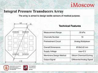
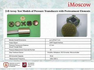
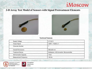


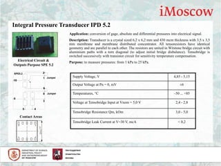

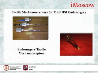
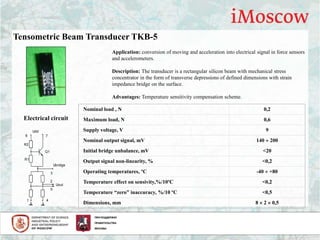
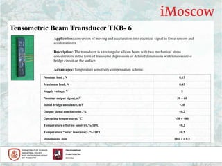
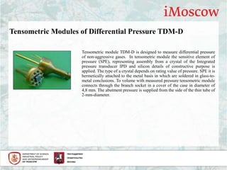
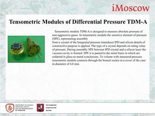
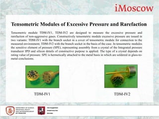

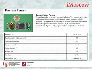


The document describes several tactile and pressure sensors developed by SMC "Technological Centre". This includes: 1) Tactile sensors based on pressure transducer arrays with 19 channels and differential analog output for medical purposes. 2) Integral pressure transducers with silicon membranes for measuring pressures from 1-25 kPa or 40-2500 kPa with analog multiplexer pre-treatment. 3) Tensometric modules for measuring differential, absolute, or excessive pressures of non-aggressive gases using integrated pressure transducers.


