Design of MechatronicsSystems
(10651684)
DEPARTMENT OF MECHATRONIS ENGINEERING
FACULTY OF ENGINEERING AND INFORMATION TECHNOLOGY
AN-NAJAH NATIONAL UNIVERSITY
2022/2023
DR. BAHAA SHAQOUR
Email: bahaa.Shaqour@najah.edu Office: 11-4-120
2.5: Force
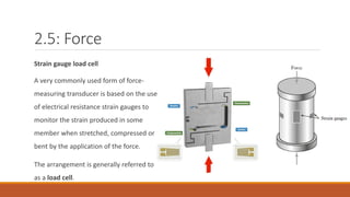
Strain gaugeload cell
A very commonly used form of force-
measuring transducer is based on the use
of electrical resistance strain gauges to
monitor the strain produced in some
member when stretched, compressed or
bent by the application of the force.
The arrangement is generally referred to
as a load cell.
4.
2.6: Fluid pressure
Manyof the devices used to monitor fluid pressure in industrial processes involve the monitoring
of the elastic deformation of diaphragms, capsules, bellows and tubes.
The types of pressure measurements that can be required are:
◦ Absolute pressure where the pressure is measured relative to zero pressure, i.e. a vacuum,
◦ Differential pressure where a pressure difference is measured and
◦ Gauge pressure where the pressure is measured relative to the barometric pressure (atmosphere
pressure).
5.
2.6: Fluid pressure
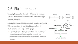
Fora diaphragm, when there is a difference in pressure
between the two sides then the center of the diaphragm
becomes displaced.
Corrugations in the diaphragm result in a greater sensitivity.
This movement can be monitored by some form of
displacement sensor, e.g. a strain gauge.
◦ A specially designed strain gauge is often used, consisting of
four strain gauges with two measuring the strain in a
circumferential direction while two measure strain in a radial
direction.
6.
2.6: Fluid pressure
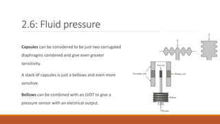
Capsulescan be considered to be just two corrugated
diaphragms combined and give even greater
sensitivity.
A stack of capsules is just a bellows and even more
sensitive.
Bellows can be combined with an LVDT to give a
pressure sensor with an electrical output.
7.
2.6: Fluid pressure
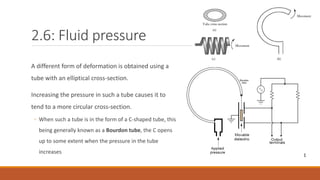
Adifferent form of deformation is obtained using a
tube with an elliptical cross-section.
Increasing the pressure in such a tube causes it to
tend to a more circular cross-section.
◦ When such a tube is in the form of a C-shaped tube, this
being generally known as a Bourdon tube, the C opens
up to some extent when the pressure in the tube
increases
8.
2.6: Fluid pressure
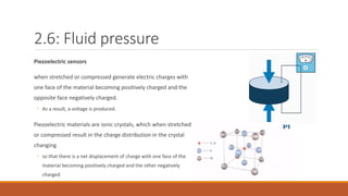
Piezoelectricsensors
when stretched or compressed generate electric charges with
one face of the material becoming positively charged and the
opposite face negatively charged.
◦ As a result, a voltage is produced.
Piezoelectric materials are ionic crystals, which when stretched
or compressed result in the charge distribution in the crystal
changing
◦ so that there is a net displacement of charge with one face of the
material becoming positively charged and the other negatively
charged.
9.
2.6: Fluid pressure
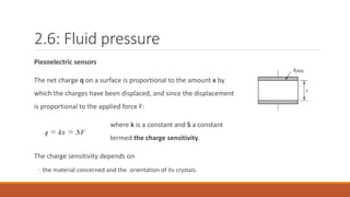
Piezoelectricsensors
The net charge q on a surface is proportional to the amount x by
which the charges have been displaced, and since the displacement
is proportional to the applied force F:
where k is a constant and S a constant
termed the charge sensitivity.
The charge sensitivity depends on
◦ the material concerned and the orientation of its crystals.
10.
2.6: Fluid pressure
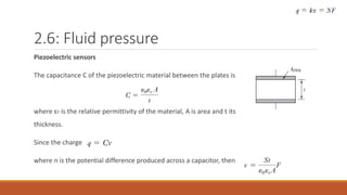
Piezoelectricsensors
The capacitance C of the piezoelectric material between the plates is
where εr is the relative permittivity of the material, A is area and t its
thickness.
Since the charge
where n is the potential difference produced across a capacitor, then
11.
2.6: Fluid pressure
Piezoelectricsensors
The force F is applied over an area A and so the applied pressure p is F/A and if we
write
this being termed the voltage sensitivity factor,
Then
The voltage is proportional to the applied pressure.
◦ The voltage sensitivity for quartz is about 0.055 V/m Pa. For barium titanate it is about
0.011 V/m Pa.
12.
2.6: Fluid pressure
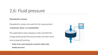
Piezoelectricsensors
Piezoelectric sensors are used for the measurement
of pressure, force and acceleration.
The applications have, however, to be such that the
charge produced by the pressure does not have much
time to leak off and thus
◦ Tends to be used mainly for transient rather than
steady pressures.
13.
2.6: Fluid pressure
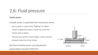
Tactilesensor
A tactile sensor is a particular form of pressure sensor.
◦ Such a sensor is used on the ‘fingertips’ of robotic
‘hands’ to determine when a ‘hand’ has come into
contact with an object.
◦ They are also used for ‘touch display’ screens where a
physical contact has to be sensed.
One form of tactile sensor uses piezoelectric
polyvinylidene fluoride (PVDF) film.
14.
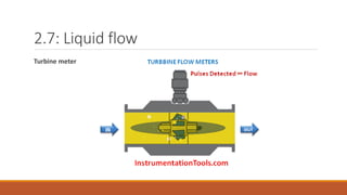
2.7: Liquid flow
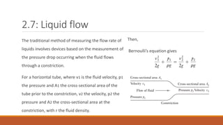
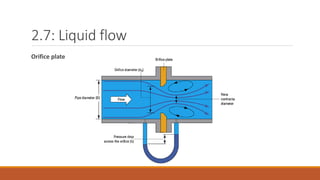
Thetraditional method of measuring the flow rate of
liquids involves devices based on the measurement of
the pressure drop occurring when the fluid flows
through a constriction.
For a horizontal tube, where v1 is the fluid velocity, p1
the pressure and A1 the cross-sectional area of the
tube prior to the constriction, v2 the velocity, p2 the
pressure and A2 the cross-sectional area at the
constriction, with r the fluid density.
Then,
Bernoulli’s equation gives
15.
2.7: Liquid flow
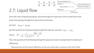
Sincethe mass of liquid passing per second through the tube prior to the constriction must
equal that passing through the tube at the constriction,
we have
But the quantity Q of liquid passing through the tube per second is
Hence
Thus, the quantity of fluid flowing through the pipe per second is proportional to √(pressure
difference).
◦ Measurements of the pressure difference can thus be used to give a measure of the rate of flow.
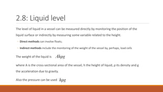
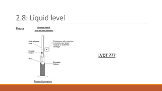
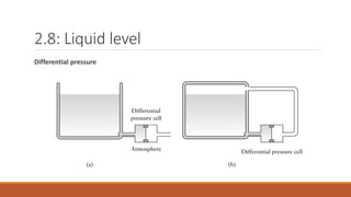
2.8: Liquid level
Thelevel of liquid in a vessel can be measured directly by monitoring the position of the
liquid surface or indirectly by measuring some variable related to the height.
◦ Direct methods can involve floats;
◦ Indirect methods include the monitoring of the weight of the vessel by, perhaps, load cells
The weight of the liquid is
where A is the cross-sectional area of the vessel, h the height of liquid, ρ its density and g
the acceleration due to gravity.
Also the pressure can be used
2.9: Temperature
Changes thatare commonly used to monitor temperature are
◦ the expansion or contraction of solids, liquids or gases,
◦ the change in electrical resistance of conductors and semiconductors
and
◦ thermoelectric e.m.f.s.
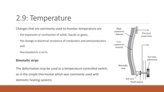
Bimetallic strips
The deformation may be used as a temperature-controlled switch,
as in the simple thermostat which was commonly used with
domestic heating systems
22.
2.9: Temperature
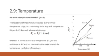
Resistance temperaturedetectors (RTDs)
The resistance of most metals increases, over a limited
temperature range, in a reasonably linear way with temperature
(Figure 2.47). For such a linear relationship:
where Rt is the resistance at a temperature t(°C), R0 the
resistance at 0°C and a α constant for the metal termed the
temperature coefficient of resistance
23.
2.9: Temperature
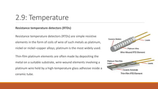
Resistance temperaturedetectors (RTDs)
Resistance temperature detectors (RTDs) are simple resistive
elements in the form of coils of wire of such metals as platinum,
nickel or nickel–copper alloys; platinum is the most widely used.
Thin-film platinum elements are often made by depositing the
metal on a suitable substrate, wire-wound elements involving a
platinum wire held by a high-temperature glass adhesive inside a
ceramic tube.
24.
2.9: Temperature
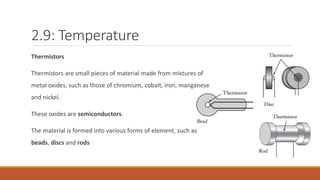
Thermistors
Thermistors aresmall pieces of material made from mixtures of
metal oxides, such as those of chromium, cobalt, iron, manganese
and nickel.
These oxides are semiconductors.
The material is formed into various forms of element, such as
beads, discs and rods
25.
2.9: Temperature
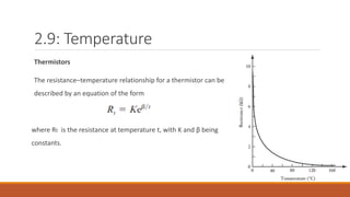
Thermistors
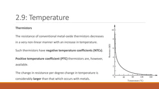
The resistanceof conventional metal-oxide thermistors decreases
in a very non-linear manner with an increase in temperature.
Such thermistors have negative temperature coefficients (NTCs).
Positive temperature coefficient (PTC) thermistors are, however,
available.
The change in resistance per degree change in temperature is
considerably larger than that which occurs with metals.
2.9: Temperature
Thermistors
Thermistors havemany advantages when compared with other temperature sensors.
◦ They are rugged and can be very small, so enabling temperatures to be monitored at virtually a point
◦ Because of their small size they respond very rapidly to changes in temperature.
◦ They give very large changes in resistance per degree change in temperature.
Their main disadvantage is their non-linearity.
Thermistors are used with the electronic systems for cars to monitor such variables as air
temperature and coolant air temperature.
28.
2.9: Temperature
Thermodiodes andtransistors
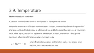
A junction semiconductor diode is widely used as a temperature sensor.
When the temperature of doped semiconductors changes, the mobility of their charge carriers'
changes, and this affects the rate at which electrons and holes can diffuse across a p–n junction.
Thus, when a p–n junction has a potential difference V across it, the current I through the
junction is a function of the temperature, being given by
where T is the temperature on the Kelvin scale, e the charge on an
electron, and k and I0 are constants.
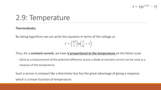
29.
2.9: Temperature
Thermodiodes
By takinglogarithms we can write the equation in terms of the voltage as
Thus, for a constant current, we have V proportional to the temperature on the Kelvin scale
◦ A2nd so a measurement of the potential difference across a diode at constant current can be used as a
measure of the temperature.
Such a sensor is compact like a thermistor but has the great advantage of giving a response
which is a linear function of temperature.
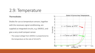
30.
2.9: Temperature
Thermodiodes
Diodes foruse as temperature sensors, together
with the necessary signal conditioning, are
supplied as integrated circuits, e.g. LM3911, and
give a very small compact sensor.
◦ The output voltage from LM3911 is proportional to
the temperature at the rate of 10 mV/°C.
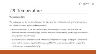
31.
2.9: Temperature
Thermotransistors
The voltageacross the junction between the base and the emitter depends on the temperature
and can be used as a measure of temperature.
◦ A common method is to use two transistors with different collector currents and determine the
difference in the base–emitter voltages between them, this difference being directly proportional to the
temperature on the Kelvin scale.
◦ Such transistors can be combined with other circuit components on a single chip to give a temperature
sensor with its associated signal conditioning, e.g. LM35. This sensor can be used in the range 240 to
110°C and gives an output of 10 mV/°C.
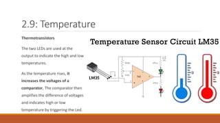
32.
2.9: Temperature
Thermotransistors
The twoLEDs are used at the
output to indicate the high and low
temperatures.
As the temperature rises, it
increases the voltages of a
comparator, The comparator then
amplifies the difference of voltages
and indicates high or low
temperature by triggering the Led.
33.
2.9: Temperature
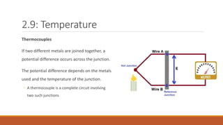
Thermocouples
If twodifferent metals are joined together, a
potential difference occurs across the junction.
The potential difference depends on the metals
used and the temperature of the junction.
◦ A thermocouple is a complete circuit involving
two such junctions
34.
2.9: Temperature
Thermocouples
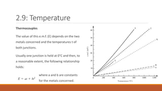
The valueof this e.m.f. (E) depends on the two
metals concerned and the temperatures t of
both junctions.
Usually one junction is held at 0°C and then, to
a reasonable extent, the following relationship
holds:
where a and b are constants
for the metals concerned.
35.
2.9: Temperature
Thermocouples
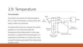
To maintainone junction of a thermocouple at
0°C, i.e. have it immersed in a mixture of ice and
water, is often not convenient.
A compensation circuit can, however, be used to
provide an e.m.f. which varies with the
temperature of the cold junction in such a way
that when it is added to the thermocouple e.m.f.
it generates a combined e.m.f. which is the same
as would have been generated if the cold junction
had been at 0°C
36.
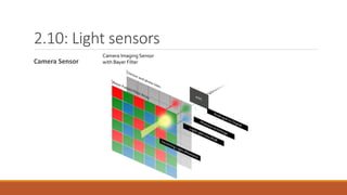
2.10: Light sensors
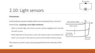
Photodiodes
semiconductorjunction diodes which are connected into a circuit in
reverse bias, so giving a very high resistance.
◦ With no incident light, the reverse current is almost negligible and is termed
the dark current.
◦ When light falls on the junction, extra hole–electron pairs are produced and
there is an increase in the reverse current and the diode resistance drops.
The reverse current is very nearly proportional to the intensity of the
light.
2.11: Selection ofsensors
In selecting a sensor for a particular application there are a number of factors that need to be
considered:
◦ The nature of the measurement required, e.g. the variable to be measured, its nominal value, the range of
values, the accuracy required, the required speed of measurement, the reliability required, the
environmental conditions under which the measurement is to be made.
◦ The nature of the output required from the sensor, this determining the signal conditioning requirements
in order to give suitable output signals from the measurement.
◦ Then possible sensors can be identified, taking into account such factors as their range, accuracy, linearity,
speed of response, reliability, maintainability, life, power supply requirements, ruggedness, availability,
cost.
39.
2.11: Selection ofsensors
E.g.:
Consider the selection of a sensor for the measurement of the level of a corrosive acid in a vessel.
◦ The level can vary from 0 to 2 m in a circular vessel which has a diameter of 1 m.
◦ The empty vessel has a weight of 100 kg.
◦ The minimum variation in level to be detected is 10 cm.
◦ The acid has a density of 1050 kg/m3 .
◦ The output from the sensor is to be electrical.
40.
2.11: Selection ofsensors
E.g.:
Because of the corrosive nature of the acid an indirect method of determining the level seems
appropriate.
◦ Thus it is possible to use a load cell, or load cells, to monitor the weight of the vessel.
◦ Such cells would give an electrical output.
The weight of the liquid changes from 0 when empty to, when full, 1050 * 2 * π(1²/4) * 9.8 = 16.2 kN.
◦ Adding this to the weight of the empty vessel gives a weight that varies from about 1 to 17 kN.
The resolution required is for a change of level of 10 cm, i.e. a change in weight of 0.10 * 1050 π(1²/4) *
9.8 = 0.8 kN.
If three load cells are used to support the tank then each will require a range of about 0 to 6 kN with
41.
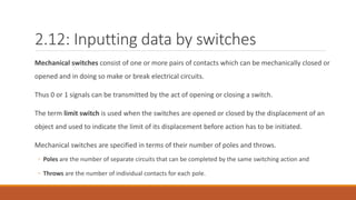
2.12: Inputting databy switches
Mechanical switches consist of one or more pairs of contacts which can be mechanically closed or
opened and in doing so make or break electrical circuits.
Thus 0 or 1 signals can be transmitted by the act of opening or closing a switch.
The term limit switch is used when the switches are opened or closed by the displacement of an
object and used to indicate the limit of its displacement before action has to be initiated.
Mechanical switches are specified in terms of their number of poles and throws.
◦ Poles are the number of separate circuits that can be completed by the same switching action and
◦ Throws are the number of individual contacts for each pole.
42.
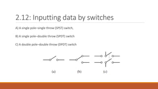
2.12: Inputting databy switches
A) A single pole–single throw (SPST) switch,
B) A single pole–double throw (SPDT) switch
C) A double pole–double throw (DPDT) switch
43.
2.12: Inputting databy switches
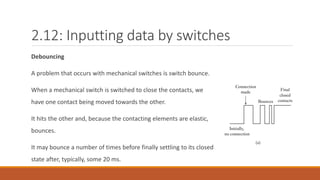
Debouncing
A problem that occurs with mechanical switches is switch bounce.
When a mechanical switch is switched to close the contacts, we
have one contact being moved towards the other.
It hits the other and, because the contacting elements are elastic,
bounces.
It may bounce a number of times before finally settling to its closed
state after, typically, some 20 ms.
44.
2.12: Inputting databy switches
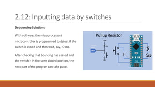
Debouncing-Solutions
With software, the microprocessor/
microcontroller is programmed to detect if the
switch is closed and then wait, say, 20 ms.
After checking that bouncing has ceased and
the switch is in the same closed position, the
next part of the program can take place.
45.
2.12: Inputting
data byswitches
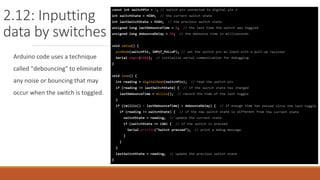
Arduino code uses a technique
called "debouncing" to eliminate
any noise or bouncing that may
occur when the switch is toggled.
46.
2.12: Inputting databy switches
Debouncing-Solutions
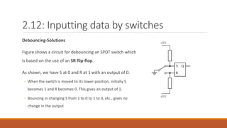
Figure shows a circuit for debouncing an SPDT switch which
is based on the use of an SR flip-flop.
As shown, we have S at 0 and R at 1 with an output of 0.
◦ When the switch is moved to its lower position, initially S
becomes 1 and R becomes 0. This gives an output of 1.
◦ Bouncing in changing S from 1 to 0 to 1 to 0, etc., gives no
change in the output
47.
2.12: Inputting databy switches
Debouncing-Solutions
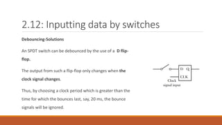
An SPDT switch can be debounced by the use of a D flip-
flop.
The output from such a flip-flop only changes when the
clock signal changes.
Thus, by choosing a clock period which is greater than the
time for which the bounces last, say, 20 ms, the bounce
signals will be ignored.
48.
2.12: Inputting databy switches
Debouncing-Solutions
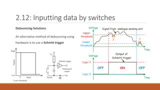
An alternative method of debouncing using
hardware is to use a Schmitt trigger
49.
2.12: Inputting databy switches
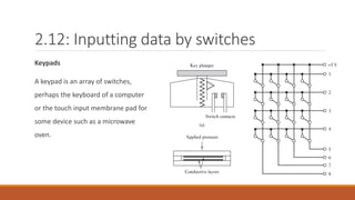
Keypads
A keypad is an array of switches,
perhaps the keyboard of a computer
or the touch input membrane pad for
some device such as a microwave
oven.