Downloaded 207 times
![Analog modules
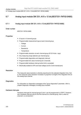
6.7 Analog input module SM 331; AI 8 x 12 bit;(6ES7331-7KF02-0AB0)
S7-300 Module data
376 Manual, 02/2013, A5E00105505-08
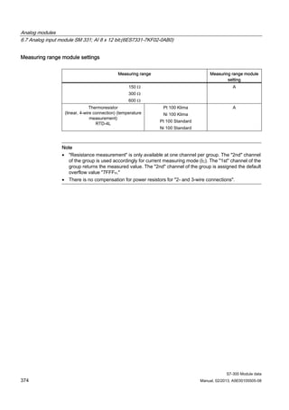
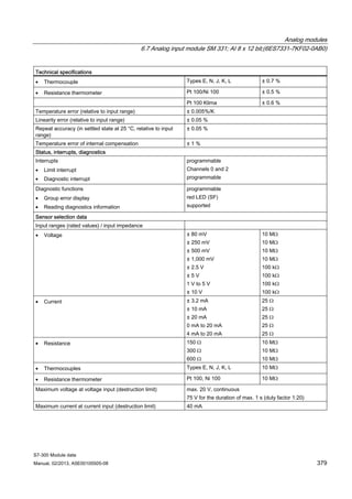
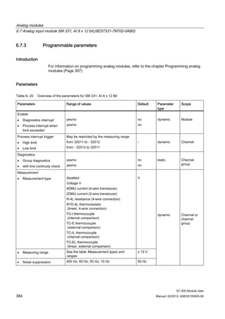
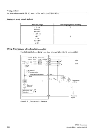
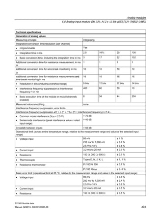
Measuring range module settings
Measuring range Measuring range module setting
Thermocouple TC-I
(internal comparison) (thermal
voltage measurement)
Linearization is ignored
Thermocouple TC-E
(external comparison)
(thermovoltage measurement)
Linearization is ignored
Type N [NiCrSi-NiSi]
Type E [NiCr-CuNi]
Type J [Fe-CuNi]
Type K [NiCr-Ni]
Type L [Fe-CuNi]
A
Thermocouple
(linear, internal comparison)
(temperature measurement) TC-
IL
Thermocouple
(linear, external comparison)
(temperature measurement) TC-
EL
Type N [NiCrSi-NiSi]
Type E [NiCr-CuNi]
Type J [Fe-CuNi]
Type K [NiCr-Ni]
Type L [Fe-CuNi]
A
Note
• An interconnection of M- and MANA is prohibited when using grounded thermocouples. In
this case, you must ensure that low-resistance equipotential bonding is in place so that
the permitted common-mode voltage is not exceeded.
• Interconnect M- and MANA when using non-grounded thermocouples](https://image.slidesharecdn.com/6es7331-7kf02-0ab0manual-160830145621/85/6ES7331-7KF02-0AB0-manual-7-320.jpg)
![Analog modules
6.7 Analog input module SM 331; AI 8 x 12 bit;(6ES7331-7KF02-0AB0)
S7-300 Module data
382 Manual, 02/2013, A5E00105505-08
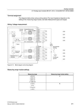
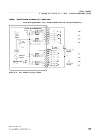
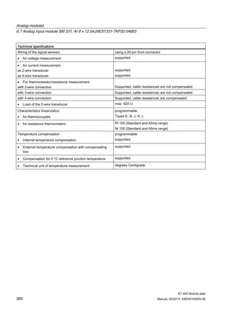
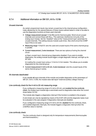
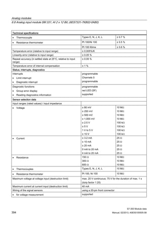
Measurement types and ranges
Table 6- 18 Measurement types and ranges
Selected type of measurement Measuring range
(type of sensor)
Measuring range module
settings
± 80 mV
± 250 mV
± 500 mV
± 1000 mV
AVoltage
V
± 2.5 V
± 5 V
1 V to 5 V
± 10 V
B
Thermocouple
TC-I
(internal comparison) (thermal voltage
measurement)
Linearization is ignored
Thermocouple
TC-E
(external comparison) (thermovoltage
measurement)
Linearization is ignored
Type N [NiCrSi-NiSi]
Type E [NiCr-CuNi]
Type J [Fe-CuNi]
Type K [NiCr-Ni]
Type L [Fe-CuNi]
A
Thermocouple
(linear, internal comparison)
(temperature measurement) TC-IL
Thermocouple
(linear, external comparison)
(temperature measurement) TC-EL
Type N [NiCrSi-NiSi]
Type E [NiCr-CuNi]
Type J [Fe-CuNi]
Type K [NiCr-Ni]
Type L [Fe-CuNi]
A
Current (2-wire transducer)
2DMU
4 mA to 20 mA D
Current (4-wire transducer)
4DMU
± 3.2 mA
± 10 mA
0 mA to 20 mA
4 mA to 20 mA
± 20 mA
C
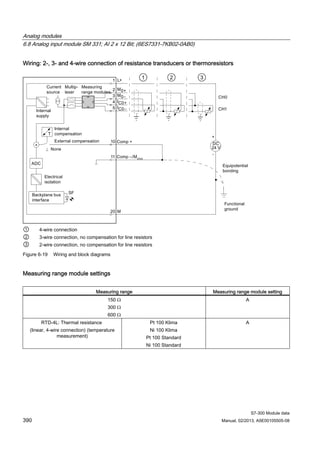
Resistance (4-wire connection)
R-4L
150 Ω
300 Ω
600 Ω
A
Thermoresistor
(linear, 4-wire connection) (temperature
measurement)
RTD-4L
Pt 100 Klima
Ni 100 Klima
Pt 100 Standard
Ni 100 Standard
A](https://image.slidesharecdn.com/6es7331-7kf02-0ab0manual-160830145621/85/6ES7331-7KF02-0AB0-manual-13-320.jpg)
![Analog modules
6.8 Analog input module SM 331; AI 2 x 12 Bit; (6ES7331-7KB02-0AB0)
S7-300 Module data
Manual, 02/2013, A5E00105505-08 389
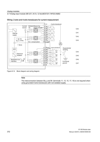
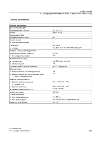
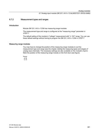
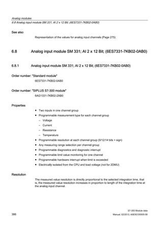
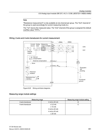
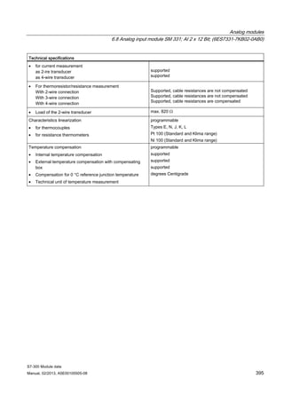
Measuring range module settings
Measuring range Measuring range module setting
TC-I: Thermocouple
(internal comparison) (thermal voltage
measurement)
TC-E: Thermocouples
(external comparison)
(thermovoltage measurement)
Type N [NiCrSi-NiSi]
Type E [NiCr-CuNi]
Type J [Fe-CuNi]
Type K [NiCr-Ni]
Type L [Fe-CuNi]
A
TC-IL: Thermocouples (linear, internal
comparison)
(temperature measurement)
Type N [NiCrSi-NiSi]
Type E [NiCr-CuNi]
Type J [Fe-CuNi]
Type K [NiCr-Ni]
Type L [Fe-CuNi]
A
TC-EL: Thermocouples
(linear, external comparison)
(temperature measurement)
Type N [NiCrSi-NiSi]
Type E [NiCr-CuNi]
Type J [Fe-CuNi]
Type K [NiCr-Ni]
Type L [Fe-CuNi]
A](https://image.slidesharecdn.com/6es7331-7kf02-0ab0manual-160830145621/85/6ES7331-7KF02-0AB0-manual-20-320.jpg)
![Analog modules
6.8 Analog input module SM 331; AI 2 x 12 Bit; (6ES7331-7KB02-0AB0)
S7-300 Module data
396 Manual, 02/2013, A5E00105505-08
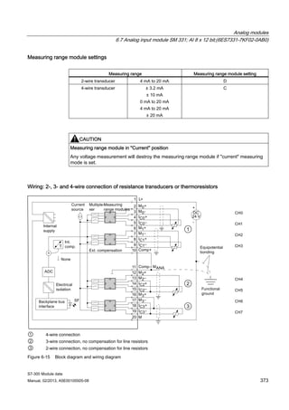
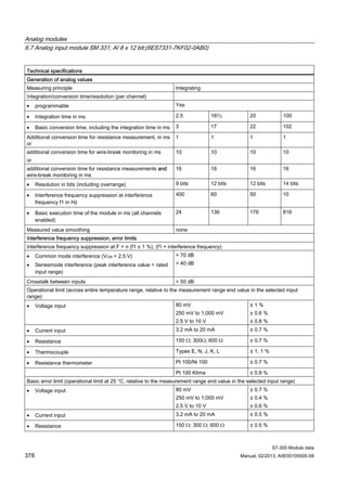
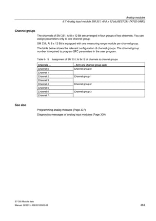
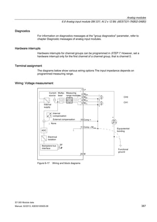
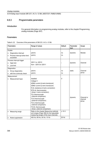
6.8.2 Measurement types and measuring ranges
Introduction
SM 331; AI 2 x 12 Bit is equipped with a measuring range module. The measurement type
and range is configured at the "measuring range" parameter in STEP 7. You can use the
default "voltage" measurement type and "± 10 V range without having to program the
SM 331; AI 2 x 12 Bit in STEP 7.
Measuring range module
Change the position of the measuring range module to set the measurement type and range
(see the chapter Setting the measurement types and ranges of analog input channels ). The
necessary settings are also available on the module's imprint. Mark the position of the
measuring range module on the front door (see figure).
Table 6- 21 Measurement types and ranges
Selected type of measurement Measuring range
(type of sensor)
Measuring range
module settings
± 80 mV
± 250 mV
± 500 mV
± 1000 mV
AV: Voltage
± 2.5 V
± 5 V
1 V to 5 V
± 10 V
B
TC-I: Thermocouple
(internal comparison) (thermal voltage
measurement)
TC-E: Thermocouples
(external comparison)
(thermal voltage measurement)
Type N [NiCrSi-NiSi]
Type E [NiCr-CuNi]
Type J [Fe-CuNi]
Type K [NiCr-Ni]
Type L [Fe-CuNi]
A
2DMU: Current (2-wire transducer) 4 mA to 20 mA D
4DMU: Current (4-wire transducer) ± 3.2 mA
± 10 mA
0 mA to 20 mA
4 mA to 20 mA
± 20 mA
C
R-4L: Resistance
(4-wire connection)
150 Ω
300 Ω
600 Ω
A](https://image.slidesharecdn.com/6es7331-7kf02-0ab0manual-160830145621/85/6ES7331-7KF02-0AB0-manual-27-320.jpg)
![Analog modules
6.8 Analog input module SM 331; AI 2 x 12 Bit; (6ES7331-7KB02-0AB0)
S7-300 Module data
Manual, 02/2013, A5E00105505-08 397
Selected type of measurement Measuring range
(type of sensor)
Measuring range
module settings
TC-IL: Thermocouples (linear, internal
comparison)
(temperature measurement)
Type N [NiCrSi-NiSi]
Type E [NiCr-CuNi]
Type J [Fe-CuNi]
Type K [NiCr-Ni]
Type L [Fe-CuNi]
A
TC-EL: Thermocouples
(linear, external comparison)
(temperature measurement)
Type N [NiCrSi-NiSi]
Type E [NiCr-CuNi]
Type J [Fe-CuNi]
Type K [NiCr-Ni]
Type L [Fe-CuNi]
A
RTD-4L: Thermal resistance
(linear, 4-wire connection) (temperature
measurement)
Pt 100 Klima
Ni 100 Klima
Pt 100 Standard
Ni 100 Standard
A
Channel groups
The two channels of SM 331; AI 2 x 12 Bit form a channel group. You can assign parameters
only to one channel group.
SM 331; AI 2 x 12 Bit is equipped with a measuring range module for channel group 0.
Line continuity check
The line continuity check is designed only for temperature measurements (thermocouples
and thermoresistors.)
Special features of the line continuity check for the 4 mA to 20 mA measuring range
If you configured a measuring range of 4 mA to 20 mA, and enabled the line continuity
check, the analog input module logs a wire-break event to diagnostics data when the current
drops below 3.6 mA.
The module also triggers a diagnostics interrupt if this function is enabled in the program.
A wire break can only be signaled by means of the lit SF LED and the diagnostic bytes must
be evaluated in the user program if diagnostics interrupts are disabled.
If you configured a measuring range of 4 mA to 20 mA, disabled the line continuity check,
and enabled diagnostic interrupts, the module triggers a diagnostic interrupt when the
underflow value is reached.](https://image.slidesharecdn.com/6es7331-7kf02-0ab0manual-160830145621/85/6ES7331-7KF02-0AB0-manual-28-320.jpg)

The document provides information about the Analog Input Module SM 331; AI 8 x 12 bit (6ES7331-7KF02-0AB0) for the S7-300 PLC system. It describes the key properties, functions, and technical specifications of the module. The module allows for 8 analog inputs in 4 channel groups, and supports measuring voltage, current, resistance, and temperature via different sensor types. It provides programmable measurement types, resolutions, measuring ranges, and diagnostics for each channel group.


![8-sem WEGHING AND BATCHING USING PLC BY MRUNAL VYAS [Autosaved]](https://cdn.slidesharecdn.com/ss_thumbnails/cf74d1c3-3036-4c17-9f5a-adff0b8051fc-151009101939-lva1-app6892-thumbnail.jpg?width=640&height=640&fit=bounds)


