Download to read offline

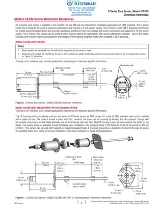
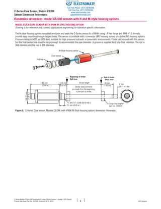
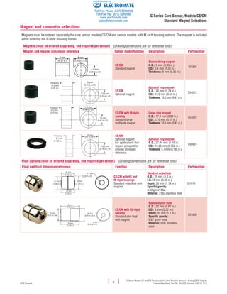
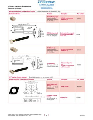

The document provides information on Temposonics C-Series Core Sensor Models CS and CM, which are magnetostrictive, absolute, non-contact linear position sensors. The sensors offer analog or SSI outputs and have stroke lengths from 72mm to 250mm. They have features such as non-contact sensing, low power needs, no drift or need for recalibration, and optional housings. Applications include medical equipment, entertainment automation, marine equipment, HVAC, food preparation equipment, and more.


