Downloaded 51 times
![Fuji Electric FA Components Systems Co., Ltd./D C Catalog
Information subject to change without notice07/26
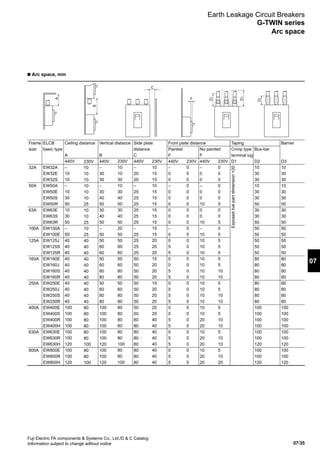
Terminal position Applicable breaker type
Code
Blank
Blank
SB
SF
S3
S4
S5
S6
S7
S8
Line
Screw
Flat teminal
Block terminal
Flat teminal
Screw
Flat teminal
Screw
Block terminal
Flat teminal
Block terminal
Load
Screw
Flat teminal
Block terminal
Flat teminal
Flat terminal
Screw
Block terminal
Screw
Block terminal
Flat terminal
EW125, 250
–
EW50, 100
–
–
–
–
–
–
EW400, 630, 800
–
–
–
–
–
–
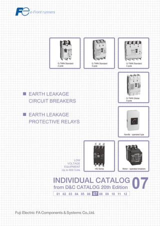
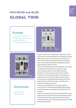
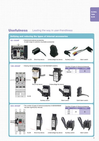
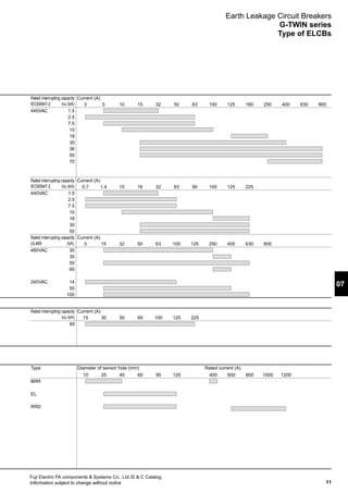
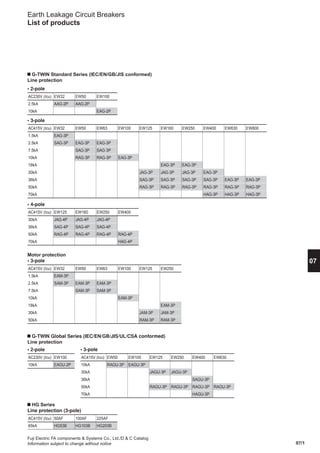
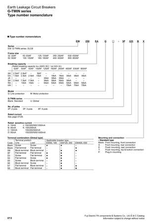
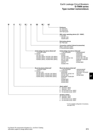
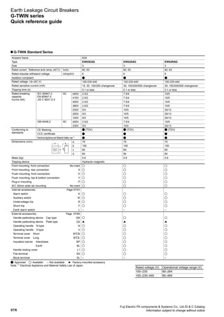
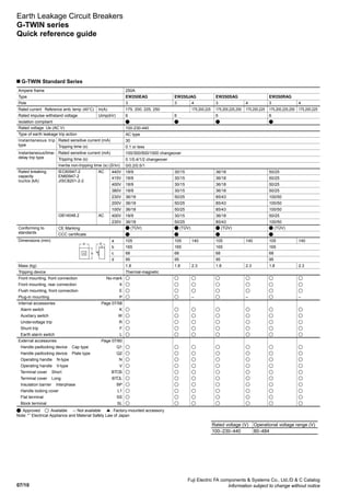
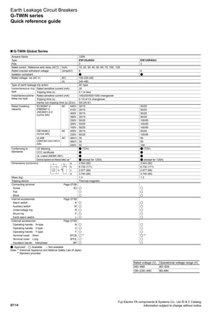
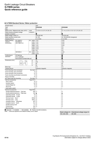
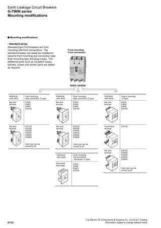
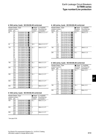
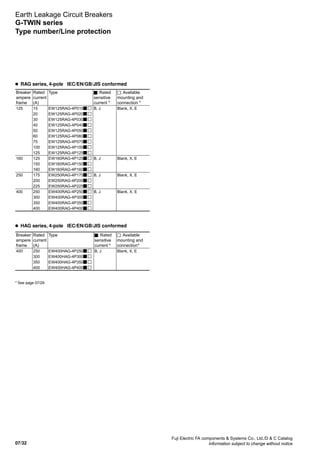
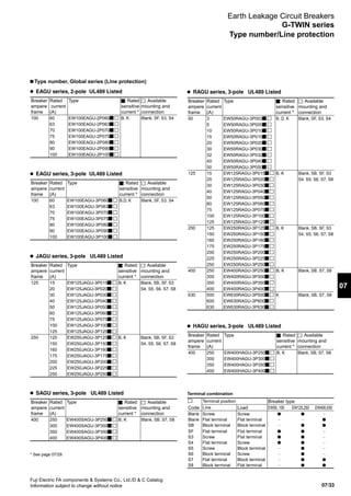
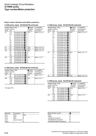
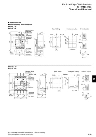
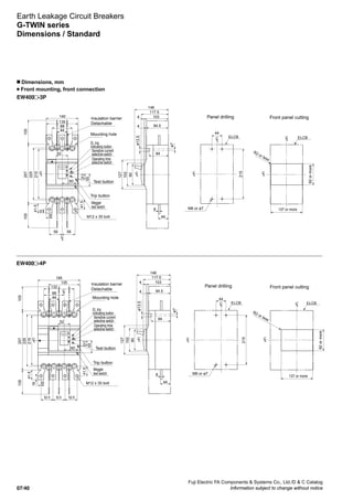
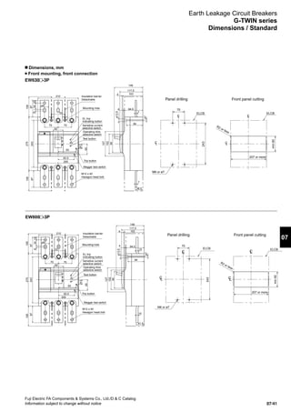
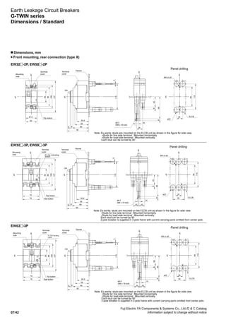
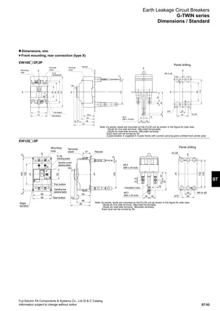
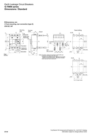
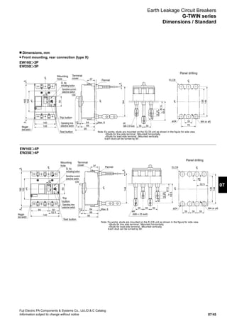
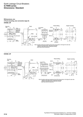
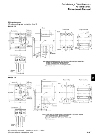
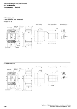
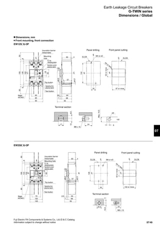
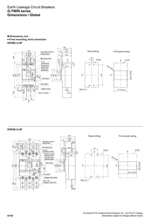
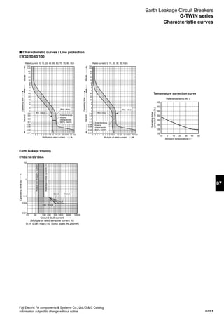
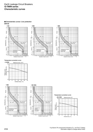
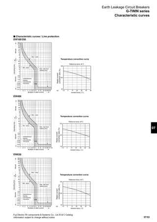
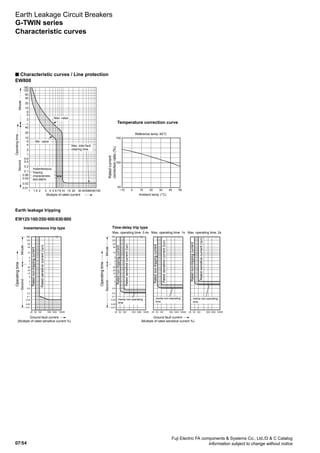
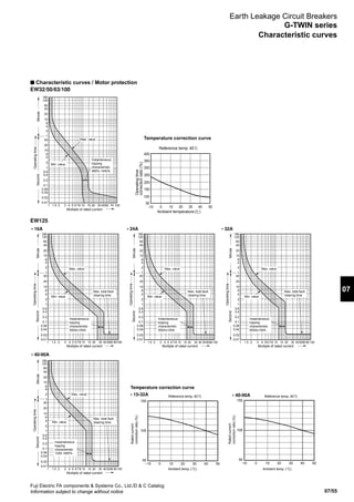
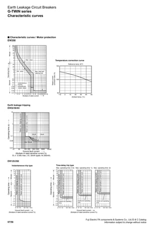
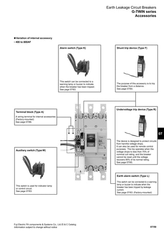
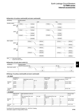
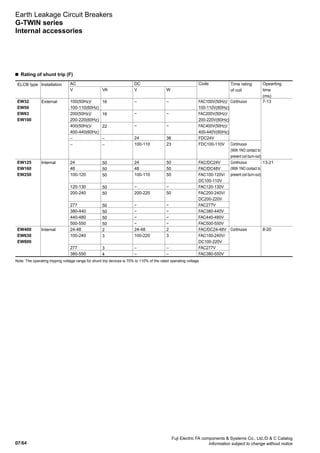
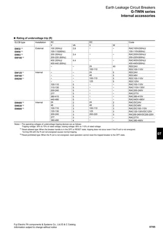
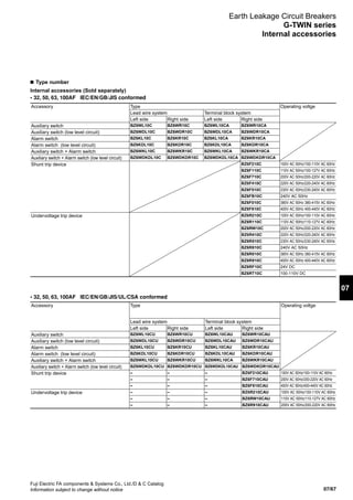
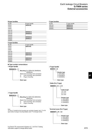
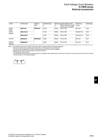
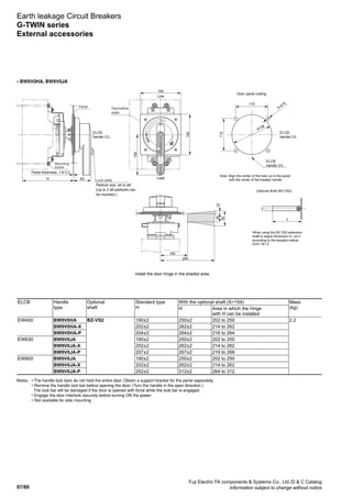
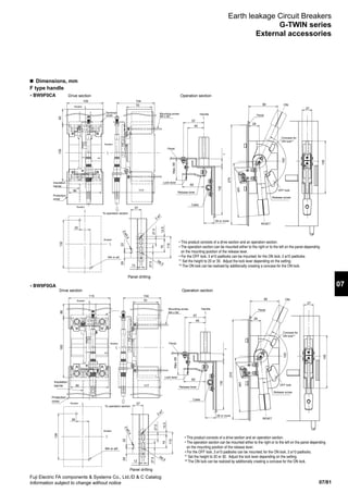
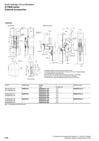
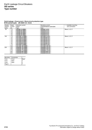
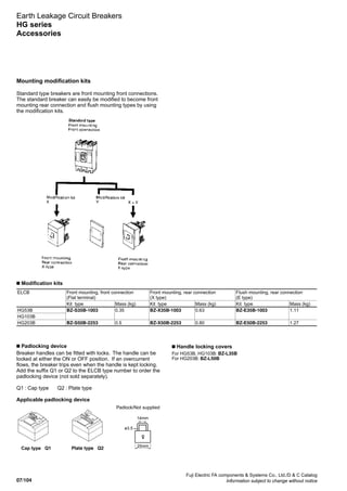
Earth Leakage Circuit Breakers
G-TWIN series
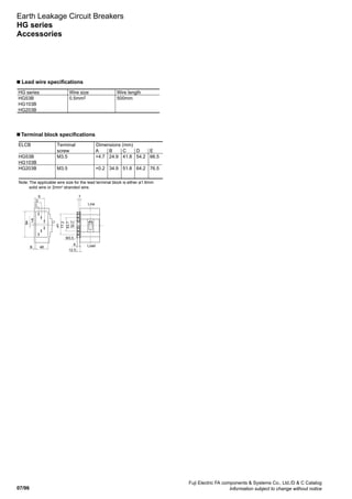
Wire size and terminal
n Notes on wiring (global series)
Notes on connecting wires (conductors)
• Connect wires to the UL breaker according to NEC (National
Electric Code) or CEC (Canadian Electrical Code) Part 1.
• Use 75°C copper wires for wiring. UL-certified or CSA-
certified wires are recommended.
• If a large current (for example, a short-circuit current)
flows, it causes a huge electromagnetic force between wires.
Therefore, be sure to secure the wires sufficiently.
• Re-tighten terminal screws periodically.
Block terminal connection
• Choose from the stranded wires shown in Table.
Wire size: AWG or MCM [mm2
] No. of wires stranded
14 to 2 [2.1 to 33.6] 7
1 to 4/0 [42.4 to 107.2] 19
250 to 500 [127 to 250] 37
Values in [ ] are those converted from AWG or MCM sizes to mm2
.
* See the instruction manual that comes with the breaker for
more details.
Precautions
• Two wires of different sizes cannot be connected to the
same block terminal.
• Be sure to use stranded wires according to Table Number
of wires stranded.
• Multi-conductor wires cannot be connected.
• Do not solder wires together.
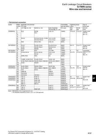
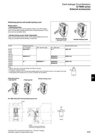
Wire size and crimp terminal
• Crimp terminal connection
ELCB Rated
current
(A)
Applicable crimp terminal
75˚C wire
Connectable wire
size (AWG)
Tightening
torque
(N•m)
Type of
screw head
and size
(mm)
J.S.T Mfg. Co., Ltd. Nichifu Co., Ltd. Daido Solderless Terminal
Mfg. Co., Ltd.
75˚C wire
EW50RAGU 3 R2-5 R2-5M
R2-5
2-S5, 2-5 14AWG 2.3-2.8 Cross/straight slotted
pan-head screw
M5 x 14
5
10
15
20 R5.5-5 R3.5-5S, R3.5-5L, 5.5-6N,
R5.5-5S, R5.5-5
3.5-5, 5.5-S5,
5.5-5, 5.5-L5
12AWG
30 10AWG
40 R8-5 R8-5S, R8-5 8-S5, 8-5 8AWG
50
EW100EAGU 60 R14-8 R14-8S, R14-8 R14-S8, R14-8 6AWG 5.5-7.5 Cross/straight slotted
pan-head screw
M8 x 15
75 22-S8 R22-8S, R22-8 R22-S8, 22-8 4AWG
100 38-S8 R38-8S 38-S8 3AWG
EW125JAGU
EW125RAGU
15 R2-8 R2-8 2-8, 2-B8 14AWG 5.8
(5.3-6.4)
Cross/straight slotted
pan-head screw
M8 x 16
20 5.5-S8, R5.5-8 R3.5-8, R5.5-8 3.5-8, 5.5-8 12AWG
30 R5.5-8 5.5-8 10AWG
40 8-8NS, R8-8 R8-8 8-8 8AWG
50
60 14-8NS, 14-S8, R14-8 R14-8S, R14-8 14-S8, 14-8 6AWG
70 22-S8, R22-8, CB22-S8 R22-8S, R22-8, CB22-8S 22-S8, 22-8, CB22-8 4AWG
75
80
90 38-S8 R38-8S 38-S8 3AWG
100
125 1AWG
EW250JAGU
EW250RAGU
125 38-S8, R38-8 R38-8S, R38-8 38-S8, 38-8 1AWG 10.5
(8-13)
Hexagon socket
head bolt
M8 x 16
150 60-S8, R60-8 R60-8, CB60-8, CB60-8S 60-8, CB60-8 1/0AWG
175 70-8 R70-8 70-8 2/0AWG
200 CB80-S8 CB80-8 3/0AWG
225 CB100-S8 CB100-8 4/0AWG
250 CB150-S8 CB150-8 CB150-8 250MCM
Notes: • AWG/MCM is the UL approved wire unit.
• The allowable temperature of wire is 75˚C. (UL CSA approved)
• Be sure to use UL-certified or CSA-certified crimp tools commercially available.](https://image.slidesharecdn.com/dec2007-elcb-141201203620-conversion-gate02/85/07-ELCB-Fuji-Electric-40-320.jpg)
![07/88
Fuji Electric FA components Systems Co., Ltd./D C Catalog
Information subject to change without notice
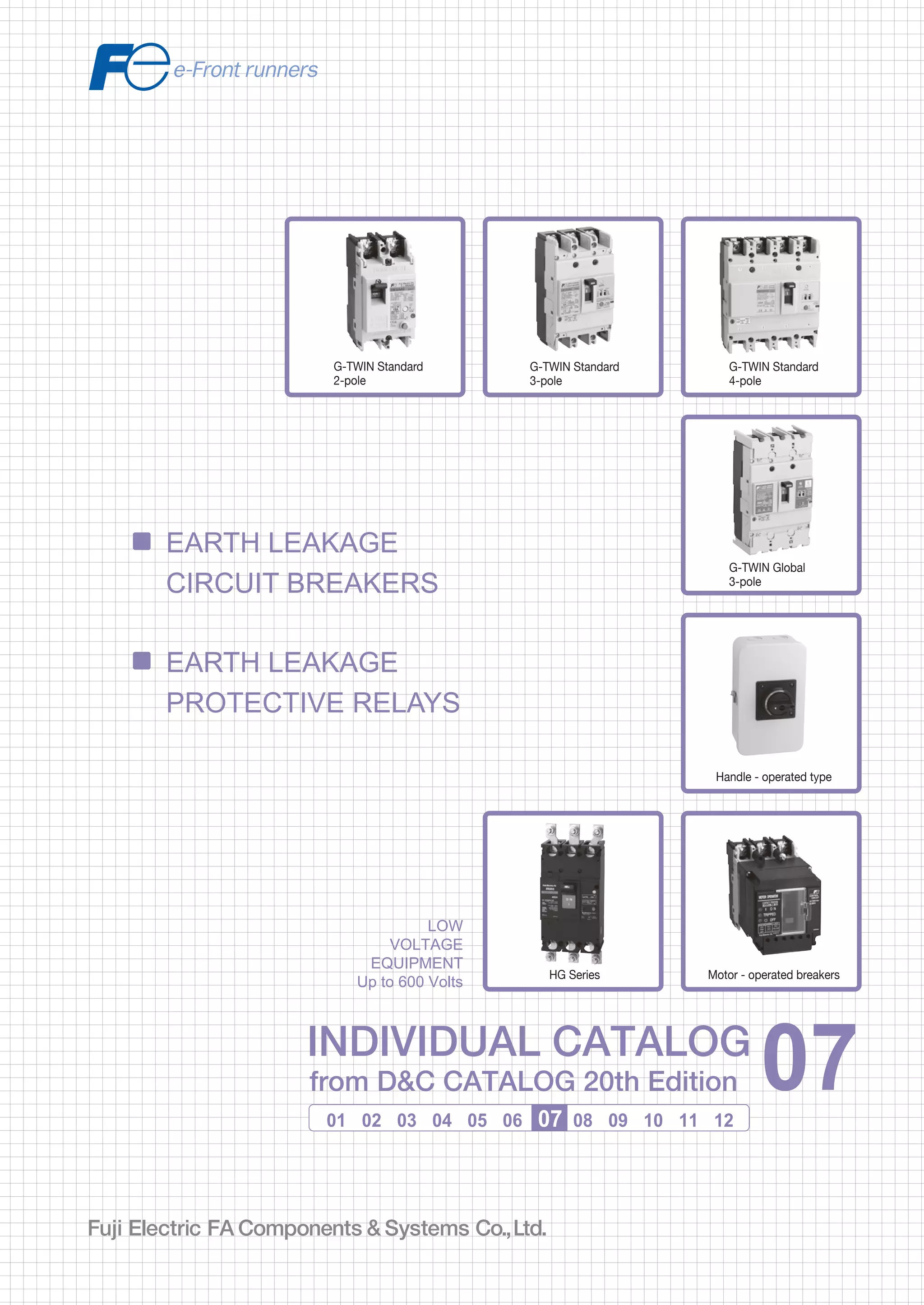
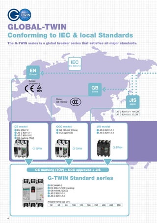
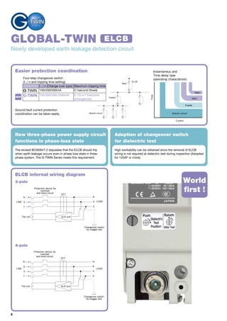
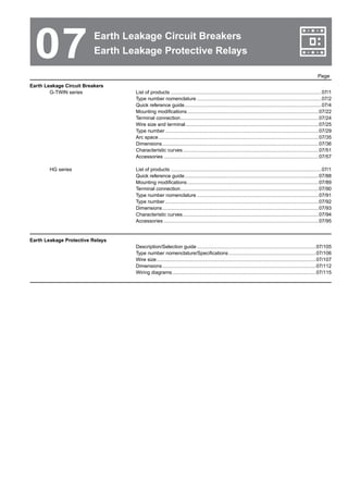
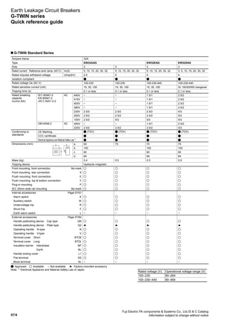
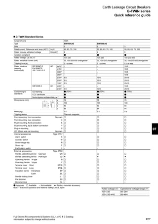
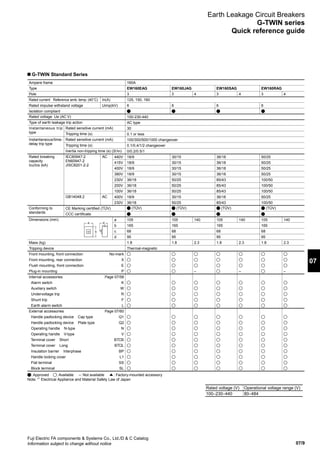
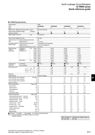
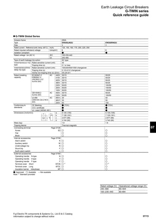
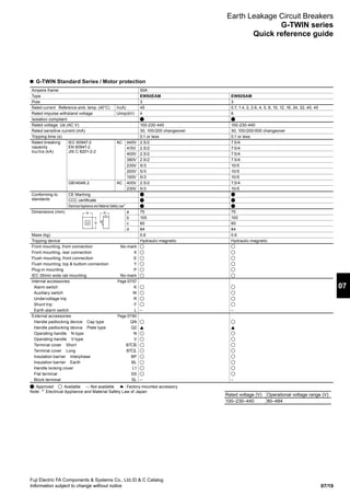
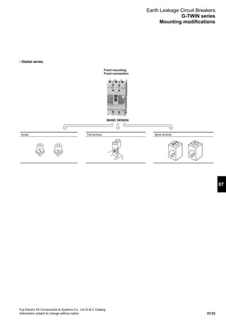
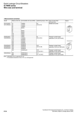
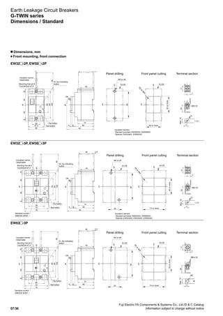
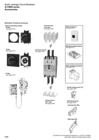
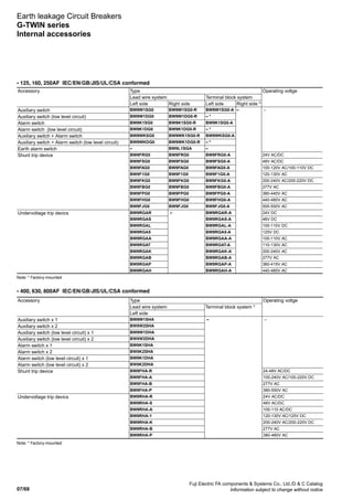
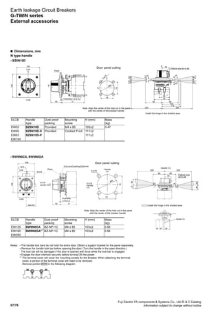
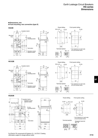
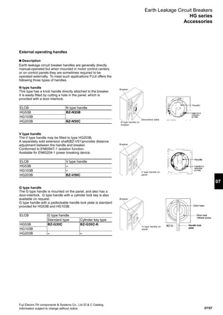
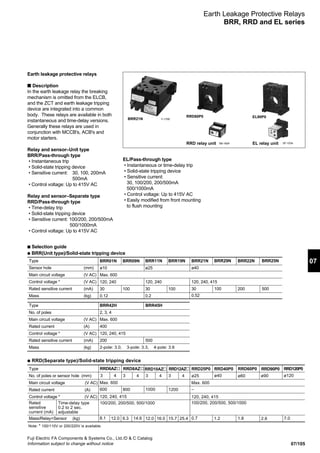
Earth Leakage Circuit Breakers
HG series
Quick reference guide
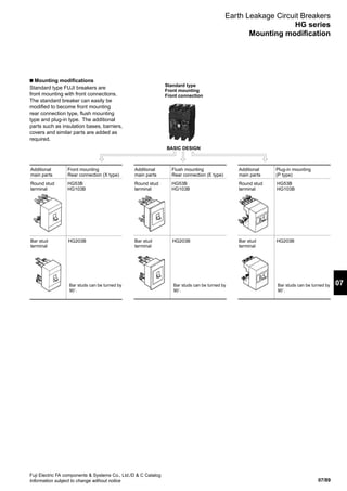
n HG series/Line protection
Frame
Pole
Type Instantaneous trip type
Time delay trip type
Phase and wire
Rated current (A) Ambient temp.: 40˚C
Rated voltage (V AC) Instantaneous trip type
[JIS C 8201-2-2 Ann.2] Time delay trip type
Instantaneous trip type Rated sensitive current (mA)
Tripping time (s)
Time delay trip type Rated sensitive current (mA)
Tripping time (s)
Inertia non-tripping time (s) [2I∆n]
Rated breaking capacity 440V AC
(kA) 415V AC
[JIS C 8201-2-2 Ann.2] 400V AC
200V AC
100V AC
Earth leakage tripping device
Overcurrent tripping device
Dimensions a
(mm) b
c
Page 07/00 d
Mass (kg) Front mounting type
Front mounting, front connection No-mark
rear connection X
Flush mounting, rear connection E
top bottom connection Y
Plug-in mounting P
Alarm switch K
Auxiliary switch W
Undervoltage trip R
Shunt trip F
Test lead wire TL
Megger test switch MGS
Motor operating mechanism M*
Padlocking device Q
Mechanical interlocking device M1
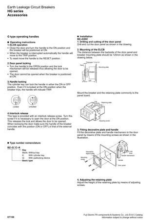
Operating handle N-type N
Operating handle V-type V
Operating handle G-type G
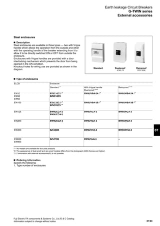
Steel enclosure C
Steel enclosure with G-type handle CG
Terminal cover Short TS
Terminal cover Long TB
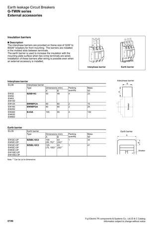
Insulation barrier Interphase B
Insulation barrier Earth BL
50A
3
HG53B
HG53BD
3ø3W, 1ø3W, 1ø2W
15, 20, 30, 40, 50
100–230–440
200–440
30, 100/200/500
0.1
100/200/500
0.3/0.8/2
0.15/0.4/1
65
65
65
100
100
Solid-state
Thermal-magnetic
90
155
82
104
2.3
–
–
–
BZ-M130C-3
BZ-N35B
–
BZ-G35C
BZ-C35B
(CG-type BZ-CG35B)
BZ-TS35B
BZ-TB35B
BZ-B35B
BZ-BL35B
100A
3
HG103B
HG103BD
3ø3W, 1ø3W, 1ø2W
15, 20, 30, 40, 50, 60, 75, 100
100–230–440
200–440
30, 100/200/500
0.1
100/200/500
0.3/0.8/2
0.15/0.4/1
65
65
65
100
100
Solid-state
Thermal-magnetic
90
155
82
104
2.3
–
–
–
BZ-M130C-3
BZ-N35B
–
BZ-G35C
BZ-C35B
(CG-type BZ-CG35B)
BZ-TS35B
BZ-TB35B
BZ-B35B
BZ-BL35B
225A
3
HG203B
HG203BD
3ø3W, 1ø3W, 1ø2W
125, 150, 175, 200, 225
100–230–440
200–440
30, 100/200/500
0.1
100/200/500
0.3/0.8/2
0.15/0.4/1
65
65
65
100
100
Solid-state
Thermal-magnetic
105
165
99
127
3.3
–
–
–
BZ-M140C
BZ-N50C
BZ-V50C
–
BZ-C50B
–
BZ-TS50B
BZ-TB50B
BZ-B50B
BZ-BL50B
c
a d
b
Factory-mounted accessoryAvailable – Not availableNotes: • Terminal covers (Height: 5mm) are standard provided for the X
and P mounting types of 50AF to 225AF.
• Time delay trip types are also available on request.
* For motor-operated breaker, sensitive current and tripping time are fixed.
Specify the sensitive current and tripping time when ordering.
Rated voltage (V) Operational voltage range (V)
100–200–415 80–484
200-440 160-484](https://image.slidesharecdn.com/dec2007-elcb-141201203620-conversion-gate02/85/07-ELCB-Fuji-Electric-102-320.jpg)
![07/111
07
Fuji Electric FA Components Systems Co., Ltd./D C Catalog
Information subject to change without notice
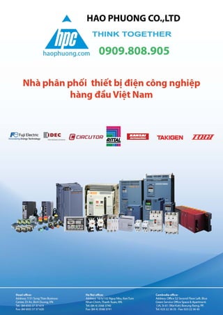
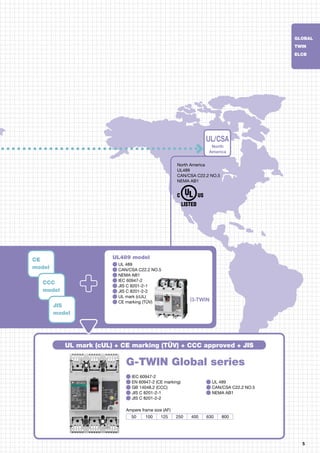
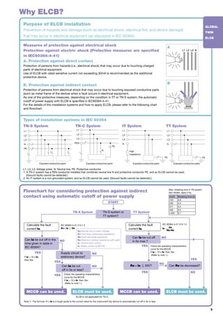
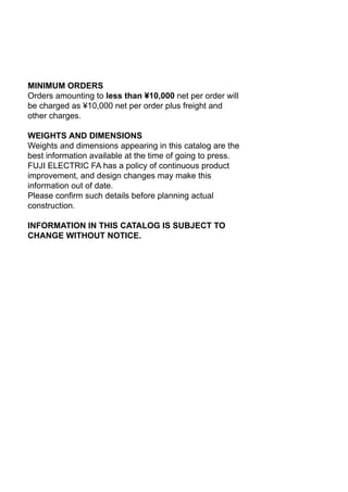
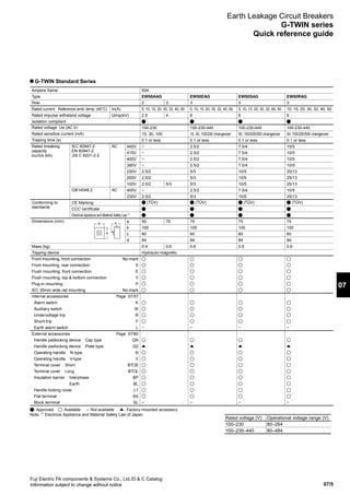
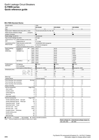
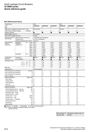
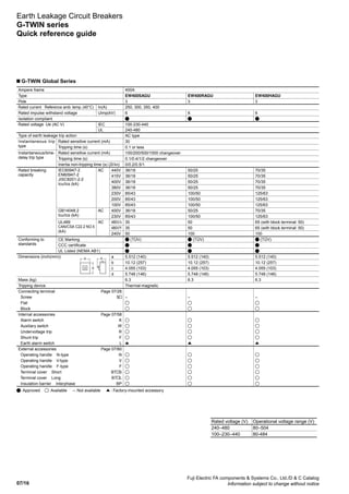
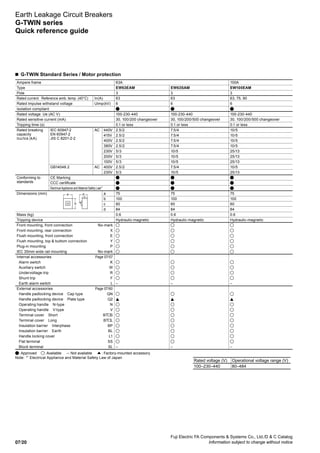
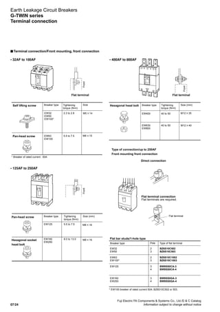
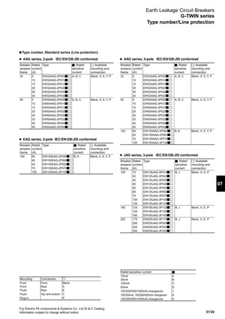
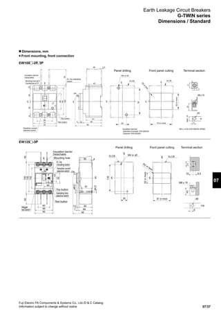
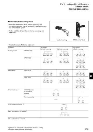
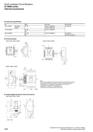
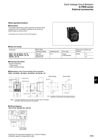
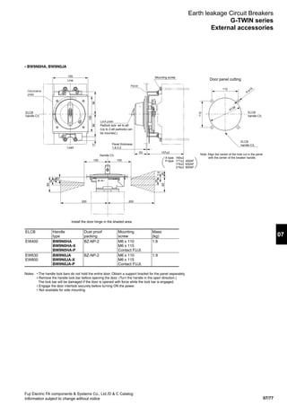
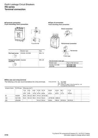
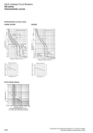
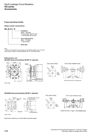
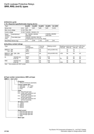
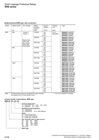
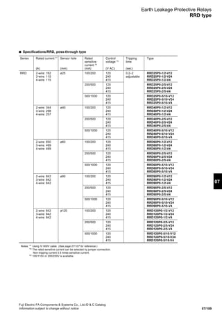
Earth Leakage Protective Relays
EL types
■ Specifications/EL type, UL 1053 recognized [UL File No. E176596]
Series Sensor Rated Control Tripping Type
hole sensitive voltage time
current 24 VAC/DC 100/200 VAC 120/240 VAC
(mm) (mA) (sec) Control Control Control
EL ø25 30 24 VAC/DC 0.1 EL25P0-30MA-AD24-00415UL EL25P0-30MA-00415UL EL25P0-30MA-V12-00415UL
50/100 100/200 VAC EL25P0-05/1-AD24-00415UL EL25P0-05/1-00415UL EL25P0-05/1-V12-00415UL
100/200 120/240 VAC EL25P0-1/2-AD24-00415UL EL25P0-1/2-00415UL EL25P0-1/2-V12-00415UL
200/500 EL25P0-2/5-AD24-00415UL EL25P0-2/5-00415UL EL25P0-2/5-V12-00415UL
500/1000 EL25P0-5/10-AD24-00415UL EL25P0-5/10-00415UL EL25P0-5/10-V12-00415UL
ø40 30 EL40P0-30MA-AD24-00415UL EL40P0-30MA-00415UL EL40P0-30MA-V12-00415UL
50/100 EL40P0-05/1-AD24-00415UL EL40P0-05/1-00415UL EL40P0-05/1-V12-00415UL
100/200 EL40P0-1/2-AD24-00415UL EL40P0-1/2-00415UL EL40P0-1/2-V12-00415UL
200/500 EL40P0-2/5-AD24-00415UL EL40P0-2/5-00415UL EL40P0-2/5-V12-00415UL
500/1000 EL40P0-5/10-AD24-00415UL EL40P0-5/10-00415UL EL40P0-5/10-V12-00415UL
ø60 30 EL60P0-30MA-AD24-00415UL EL60P0-30MA-00415UL EL60P0-30MA-V12-00415UL
50/100 EL60P0-05/1-AD24-00415UL EL60P0-05/1-00415UL EL60P0-05/1-V12-00415UL
100/200 EL60P0-1/2-AD24-00415UL EL60P0-1/2-00415UL EL60P0-1/2-V12-00415UL
200/500 EL60P0-2/5-AD24-00415UL EL60P0-2/5-00415UL EL60P0-2/5-V12-00415UL
500/1000 EL60P0-5/10-AD24-00415UL EL60P0-5/10-00415UL EL60P0-5/10-V12-00415UL
ø90 30 EL90P0-30MA-AD24-00415UL EL90P0-30MA-00415UL EL90P0-30MA-V12-00415UL
50/100 EL90P0-05/1-AD24-00415UL EL90P0-05/1-00415UL EL90P0-05/1-V12-00415UL
100/200 EL90P0-1/2-AD24-00415UL EL90P0-1/2-00415UL EL90P0-1/2-V12-00415UL
200/500 EL90P0-2/5-AD24-00415UL EL90P0-2/5-00415UL EL90P0-2/5-V12-00415UL
500/1000 EL90P0-5/10-AD24-00415UL EL90P0-5/10-00415UL EL90P0-5/10-V12-00415UL
ø115 30 EL115P0-30MA-AD24-00415UL EL115P0-30MA-00415UL EL115P0-30MA-V12-00415UL
50/100 EL115P0-05/1-AD24-00415UL EL115P0-05/1-00415UL EL115P0-05/1-V12-00415UL
100/200 EL115P0-1/2-AD24-00415UL EL115P0-1/2-00415UL EL115P0-1/2-V12-00415UL
200/500 EL115P0-2/5-AD24-00415UL EL115P0-2/5-00415UL EL115P0-2/5-V12-00415UL
500/1000 EL115P0-5/10-AD24-00415UL EL115P0-5/10-00415UL EL115P0-5/10-V12-00415UL
● Type number nomenclature, EL type, UL 1053 recognized
EL 25 P0 - 30MA - AD24 - 00415 UL
Special ratings in clause IV
00415 UL : UL agreement goods
Control voltage
No mark : 100/200V AC
V12 : 120/240V AC
AD24 : 24V AC/DC
Sensitivity current
30MA : 30mA (Pick-up current 22mA)
05/1 : 50/100mA (Pick-up current 40/80mA)
1/2 : 100/200mA (Pick-up current 80/160mA)
2/5 : 200/500mA (Pick-up current 160/400mA)
5/10 : 500/1000mA (Pick-up current 400/800mA)
Pass-through type
P0 : through type
Diameter of sensor hole
25 : 25mm diameter
40 : 40mm diameter
60 : 60mm diameter
90 : 90mm diameter
115 : 115mm diameter
Basic type](https://image.slidesharecdn.com/dec2007-elcb-141201203620-conversion-gate02/85/07-ELCB-Fuji-Electric-125-320.jpg)


This document details the product offerings of Fuji Electric, including low and high voltage electrical equipment such as magnetic contactors, industrial relays, circuit breakers, and earth leakage circuit breakers. It emphasizes the G-Twin series, which conforms to international standards and features environmentally friendly design innovations. Additionally, the document outlines specifications, installation guidance, and safety measures for these electrical devices.


