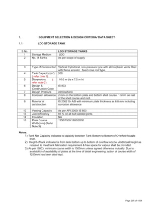
This document provides technical datasheets for a fuel oil unloading system. It includes details on:
1) LDO storage tanks such as tank capacity, dimensions, design codes, material of construction, etc.
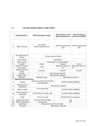
2) LDO unloading pumps and sump pumps including type, capacity, design codes, material of construction.
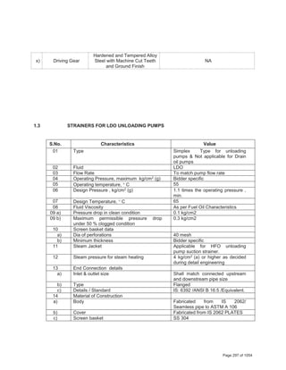
3) Strainers for LDO unloading pumps including type, flow rate, pressure, temperature, material of construction.
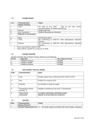
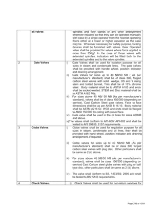
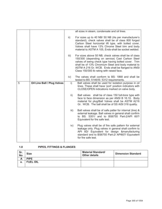
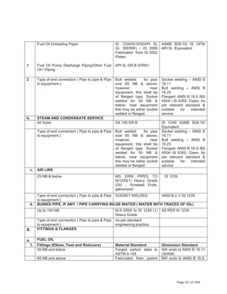
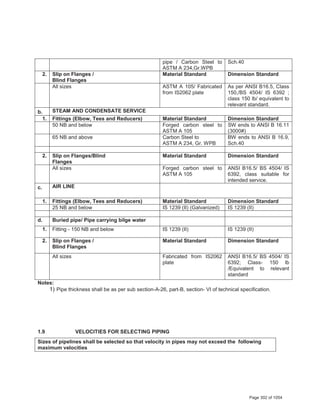
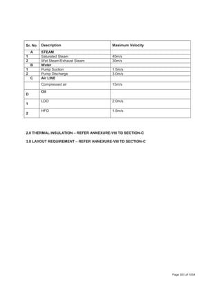
4) Additional components like steam traps, steam tracing, oil hoses, and valves are also specified.