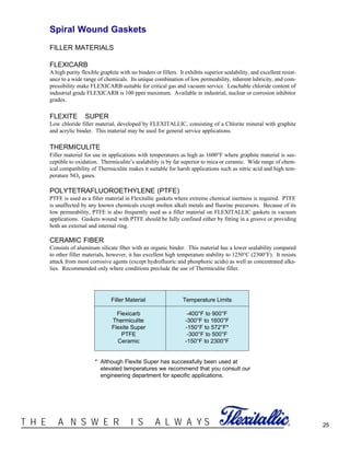
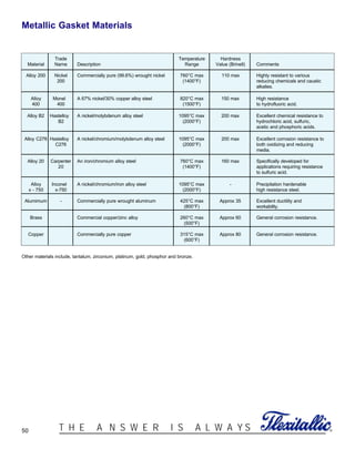
Thermiculite sheet gaskets are comprised of chemically and thermally exfoliated vermiculite reinforced with a metallic core. Vermiculite demonstrates better chemical resistance and superior high temperature sealing characteristics compared to graphite. Independent testing showed Thermiculite maintains its integrity and sealing properties at temperatures up to 870°C, whereas graphite starts to lose stress retention above 340°C due to oxidation. Thermiculite is not affected by oxidation and can provide an effective seal even at 500°C, making it suitable for demanding high temperature applications.


![38 ®T H E A N S W E R I S A L W A Y S
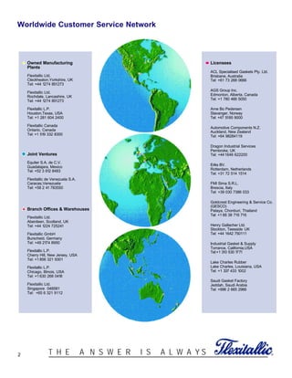
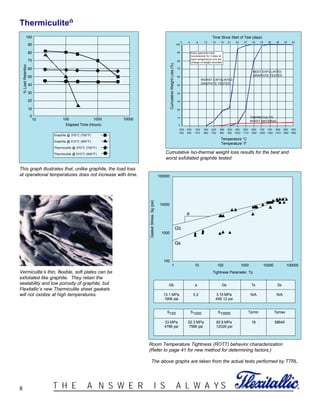
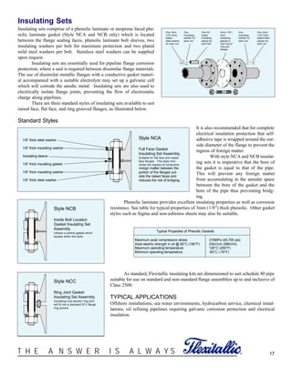
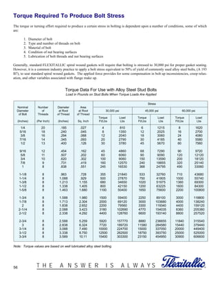
ASME Boiler and Pressure Vessel Code Calculations
Section VIII of the ASME Boiler & Pressure Vessel Code, establishes criteria for flange design and suggests values of "m" (gasket fac-
tor) and "y" (minimum gasket seating stress) as applied to gaskets. For the most part, the defined values have proven successful in actu-
al applications. However, much confusion exists regarding these values, primarily due to a misunderstanding of the definitions of the
terms and their significance in practical applications. Mandatory Appendix II, in Section VIII of the Boiler Code, requires in the design
of a bolted flange connection, complete calculations shall be made for two separate and independent sets of conditions.
Operating Conditions
Condition one (1) requires a minimum load be determined in accordance with the following equation:
This equation states the minimum required bolt load for operating conditions and is the sum of the hydrostatic end force, plus
a residual gasket load on the contact area of the gasket times a factor times internal pressure. Stated another way, this equation requires
the minimum bolt load be such that it will maintain a residual unit compressive load on the gasket area that is greater than internal pres-
sure when the total load is reduced by the hydrostatic end force.
Gasket Seating
Condition two (2) requires a minimum bolt load be determined to seat the gasket regardless of internal pressure and utilizes a formu-
la:
The "b" in these formulae is defined as the effective gasket width and "y" is defined as the minimum seating stress in psi. For
example, Section VIII of the Boiler Code suggests a minimum "y" value for a spiral wound gasket of 10,000 psi (Winter 1976
Addenda). These design values are suggested and not mandatory. The term "b" is defined as:
At this point, it is important to realize the gasket must be capable of carrying the entire compressive force applied by the bolts
when prestressed unless provisions are made to utilize a compression stop in the flange design or by the use of a compression gauge
ring. For this reason, FLEXITALLIC's standard practice is to assume W is equal to Ab Sa.
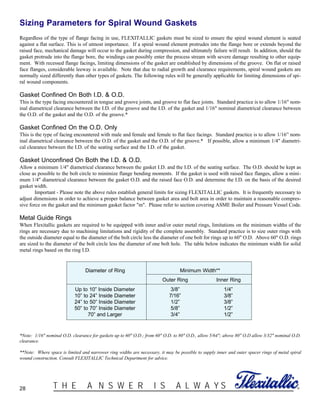
We are then able to determine the actual unit stress on the gasket bearing surface. This unit stress Sg is calculated as follows:
*Note: Based on 4.5mm (.175") thick spiral wound gasket. The “v” or Chevron shape on the gasket O.D. is not part of the effective
seating width, therefore .125” is subtracted from the actual gasket O.D.
Using the unit stress we can assign construction details which will lead to the fabrication of a gasket having sufficient density to carry
the entire bolt load.
b = bo when bo ≤1/4" b = 0.5 bo when bo > 1/4"
After Wm1, and Wm2 are determined, the minimum required bolt area Am is determined as follows:
Am = Wm1 where Sb is the allowable bolt stress at operating temperature, and
Am2 = where Sa is the allowable bolt stress at atmospheric temperature.
Then Am is equal to the greater of Am1 or Am2. Bolts are then selected so the actual bolt area, Ab, is
equal to or greater than Am.
Wm2
Sb
Sa
(1) Wm1 = + 2b 3.14GmP
3.14G
2
P
4
(2) Wm2= 3.14bGy
(3) Sg (psi) =
Ab Sa
.785 [(do - .125*)2
- (di)2
]](https://image.slidesharecdn.com/gasketdesigncriteria-150909151537-lva1-app6891/85/Gasket-design-criteria-38-320.jpg)

![42 ®T H E A N S W E R I S A L W A Y S
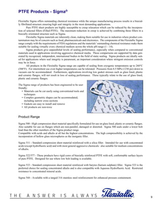
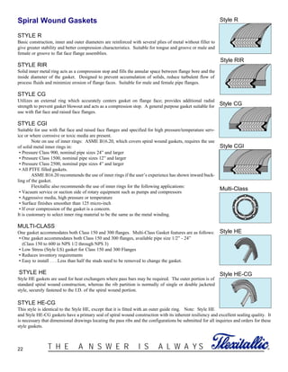
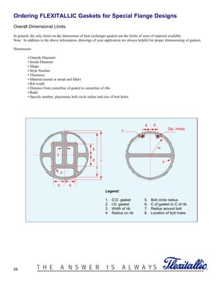
PVRC METHOD
Current gasket design calculations for bolted
joints such as ASME VIII, DIN 2505, etc., have
many shortcomings surrounding the expected
tightness and optimum operating stress levels to
ensure against joint leakage. In general, current
design methods only ensure that the optimum
bolt load is available to seat the gasket and
accommodate the hydraulic loads created by the
internal pressure. Little information is given
regarding the tightness of the joint in service or
the optimum level of gasket stress to fulfill the
legislative, environmental and company emission
requirements at the source of application.
Flexitallic financially supports, and is
actively involved in the research efforts of the
ASME's Pressure Vessel Research Council
(PVRC) to review and update current gasket
design methodology. The PVRC has, through
many years of research and development (involv-
ing hundreds of actual gasket tests), conceived a
new philosophy that addresses the mechanisms of
sealing that will benefit gasket manufacturers, vessel designers and the operators of process equipment in general. The result is a pack-
age that recommends minimum levels of gasket assembly stress to fulfill the operational requirements of the user. The new procedure
is similar to the existing ASME Section VIII calculation, except it incorporates new gasket factors (to replace the traditional m & Y
gasket factors) that have been determined through an extensive test program.
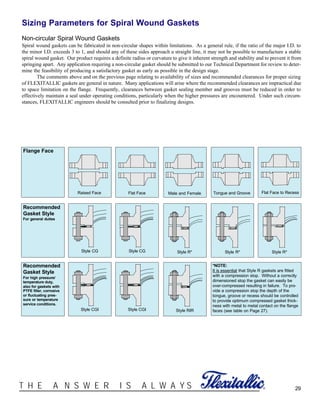
The new gasket factors are (Gb), (a), and (Gs).
(Gb) and (a) represent the initial gasket compression characteristics and relate to the initial installation, while (Gs) represents
the unloading characteristics typically associated with the operating behavior.
The PVRC method has been developed over the years using the following parameters for bolted joint designs and determining gasket
constants:
1. Determine the tightness class 'Tc' that corresponds to the acceptable leak rate for the application (legislative, environmental, or
company emission legislation).
T2: Standard; represents a mass leak rate per unit diameter of 0.002 mg/sec/mm-dia.
T3: Tight; represents a mass leak rate per unit diameter of 0.00002 mg/sec/mm-dia.
2. Select the tightness constant that corresponds to the chosen tightness class
C = 1.0 for tightness class T2 (Standard).
C = 10.0 for tightness class T3 (Tight).
3. Select the appropriate gasket constants (Gb), a, and (Gs) for the gasket style and material, (see table, page 43).
4. Determine gasket parameters (N), (bo), (b), and (G) as per table (page 40).
5. Gasket seating area, Ag = 0.7854(OD2-ID2).
6. Hydraulic area, Ai = 0.7854G2
7. Minimum required tightness, Tpmin = 0.1243 x C x Pd , Pd = Design Pressure
8. Assembly Tightness Tpa = 0.1243 x C x Pt, Pt = Test Pressure (Typically 1.5 x Pd)
9. Tightness Parameter Ratio, Tr = Log(Tpa)/Log(Tpmin)
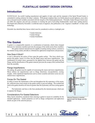
10. Gasket Operating Stress, Sm1 = Gs[Gb/Gs x Tpaa]1/Tr
10000
Tightness Parameter Tp
100010010
Gs
Gb
Gasket
Stress
a
Part A
Part B
Cycles
Tp min Tpn
Sgmin > P
Sa
Idealization of Stress vs. Tightness showing the basis
for the gasket constants Gb, a and Gs](https://image.slidesharecdn.com/gasketdesigncriteria-150909151537-lva1-app6891/85/Gasket-design-criteria-42-320.jpg)


![[IJET-V2I1P9] Authors:Wasim B. Patel,Ritesh G. Deokar,Pundlik N. Patil,Raghun...](https://cdn.slidesharecdn.com/ss_thumbnails/ijet-v2i1p9-160427182713-thumbnail.jpg?width=640&height=640&fit=bounds)


