1900 series damper with electrical and pneumatic actuator
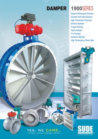
1. DAMPER 1900SERIES
Square Rectangular Damper
Variable Inlet Vane Damper
High Temperature Damper
Diverter Damper
Poppet Damper
Stack Damper
Fire Damper
Guillotion Damper
High Temperature Slide Gate
Yes. We CARE..
.
| Courteously | Attentively | Respectably | Effectively |
SUDE
An ISO 9001:2008 Certified Company
R
2. Damper
Index Introduction
Introduction ................................................ 01 For over 20 years, Sude has been the leader in designing and manufacturing
Purpose of Damper ................................... 02 durable, high performance dampers for industrial and other types of ventilation
Selection Guide ..........................................02 applications.
Damper Selection Guide ........................... 03 Sude's goal is to deliver products that meet and exceed industry standards.
Type of Dampers & its Leakage Class ....... 07 Experienced, professional engineers, and development, and the latest in
Seat Selection Guideline ........................... 07 manufacturing technology are the key ingredients that assure superiority of Sude
products.
Sealing Efficiency For Dampers ................ 08
Standard Construction Features With a history of developing original ideas, Sude is known for its innovation and use
of Butterfly Damper .................................... 09 of leading-edge technology. This includes using the latest materials to custom build
Standard Construction Features of dampers and louvers to withstand the most stringent environments.
Square / Rectangular Damper ................... 11
When it comes to industrial ventilation, contractors and engineering firms depend on
Variable Inlet Vane Damper ....................... 16
Sude to provide the industry's finest product. From light operations to heavy-duty
Typical test Bench for Dampers applications, we build dampers that meet the most demanding situations. Every
Efficiency Check ........................................ 19 damper is built with performance in mind and is designed to meet the highest
High Temperature Damper ........................ 20 specification.
Diverter Damper ........................................ 21
Since most industrial systems cannot be shut down for normal periodic maintenance,
Poppet Dampers ........................................ 23
our products are designed to support options such as exposed linkages and outboard
Stack Dampers .......................................... 25 bearing packages. These facilitate easy maintenance while the system is operational.
Fire Damper .............................................. 27
Sude works with a variety of materials, including galvanized steel, aluminum,
Guillotine Damper ...................................... 29
stainless steel etc. in order to match our customer's exact specifications. By molding
High Temperature Slide Gate .................... 32 and forming these materials, we can develop dampers to fit almost any application.
Comparison Features and
General Comments ................................... 33 The company has the technology and experience to design and manufacture multi-
blade airfoil damper. A welded frame combined with thick axles and outboard
GA Drawings.............................................. 36
bearings provide the damper with both structural integrity and performance. Perfect
Conventional System ................................. 45
for applications requiring low levels of leakage at high static pressures.
Test & Inspection........................................ 45
l
ria
st
du
l In
ea
ra
s
ub
ne
S
Ge
Sude design provides many benefits: e &
rin ipeli
ne
Lower pressure losses Ma id P
& Liqu
Low operating torque Gas
Major Food & Beverage
Operating torque not affected by
Customer Power P
lant
airflow direction through damper
Oil
&G
Minimizes pressure losses through as P
Ch rod
em uct
smaller dampers ion
ic
Air
al
Pr
Co
oc
es
nd
si
ng
itio
nin
g
01 1900 SERIES SUDE
3. Purpose of Damper
Major Purpose High Temperature
Control Air & Gas Flow Abrasive Dusty
Shut-Off Air & Gas Flow Low Cost Effect
Changing Flow Direction
Sub Purpose
Control Duct Pressure
Control Duct Temperature
Emergency Exhaust
Selection Guide
SUDE 1900 SERIES 02
4. Damper Selection Guide
SUDE
Damper Actuator Selection Criteria
The Actuator assembly for Damper the most important point is the Torque and Positioning accuracy which plays the major
role for smooth operation
Torque: 100
MAXIMUM
PERCENT OF MAXIMUM TORQUE
90
The torque that is required to operate a
80
damper depends upon the size, type, Actual torque needed varies
70
with blade type, pressure
quality & condition of the damper. It is also 60
drop, system effects, ect.
dependent upon the differential pressure & 50
40
air flow Contrary to popular belief; the
30
maximum required torque is not always at 20
the closed position. Typically, the maximum 10
NEGATIVE POSITIVE
torque requirement is found at about 30% 0
open position. Refer figure 12. 0 10 20 30 40 50 60 70 80 90
DEGREES, DAMPER ROTATION
Figure 12 : Typical Torque Requirement.
Linkage:
The actuator is connected to the damper via a linkage, which has a couple of ball joints, pivots & other elements that have
some play. The slack in the linkage can easily cause a 1 – 3% hysteresis, when the stress changes from a pulling force to
a pushing force. This effect requires the actuator to move about 1- 3% before the damper begins to move. The amount of
hysteresis depends upon the condition of the linkage & how well it has been adjusted. If the linkage is improperly adjusted
& the joints are worn, the hysteresis can actually be larger than 5%.
Damper Positioning Accuracy
Pneumatic Pneumatic Electronic Direct
Without positioner With positioner With linkage Coupled
Actuator 12% 2 ½ - 5% 1% 1%
Linkage 1 – 3% 1 – 3% 1 – 3% None
E/P Transducer 2% 2% None None
Total 15 – 17% 5 ½ - 10% 2 – 4% 1%
As it can be seen from the above table, direct coupled electronic actuators are more accurate than any other type of
actuator.
When selecting an actuator, the following criteria should be taken into careful consideration
Should the actuator be Manual, Electric or Pneumatic ?
Manual :
Locking quadrant actuators can be used if the damper's position is fixed (when used for balancing airflow) or needs to
change only occasionally (such as summer/winter changeover).
03 1900 SERIES SUDE
5. SUDE
Electric :
Easier interface with digital control devices. Electric actuators must have a voltage selected. Typical actuator voltages are
24vac, 110vac, 240 vac and 415 volts. Fail safe electric actuators are also called spring return, and the fail position (open
or closed) should be noted. For detail on the Electric actuator refer Sdtork, Pune and asked for detailed literature. The
spring return Electrical actuator are available for low torque for higher values we suggest you to use reversible stay put
type actuator.
ACCESSORIES:
? limit switches [1 NO + 1 NC or 2NO+2NC] change over type
Position
?limit switches [1 NO + 1 NC]
Travel
Hand wheel
?
Local position indication
?
OPTIONAL ACCESSORIES, CONTROL & PROTECTIONS:
Extra limit switches
?
? 2NC contacts for travel limit switches
2 NO +
? 2NC contacts for torque limit switches
2 NO +
? insulation for motor
'H' class
Side mounted hand wheels to reduce rim pull effort, geared hand wheel is provided
?
? position indicator Potentiometer, Current position transmitter, Non-contact type position transmitter
Remote
? position indicator Analog / Digital
Remote
?supply
Power
Push button station
?
? switch
Blinker
? starter
Integral
? panel
Control
Electronic positioner
?
?phase protection
Single
? control / protection features as per application demands can also be given for specific requirements.
Special
Pneumatic :
Pneumatic actuators are available in rotary construction in Double and spring return in on/off and modulating duty format.
Actuators will be inherently fail safe, but fail position (open or closed) should be noted. Pneumatic actuators are supplied
with Electro pneumatic positioners which works on continuous pressurized air of 60psi and input signal of 4 to 20mA with a
feed back of 4 to 20mA. For details refer actuator catalogue.
Accessories:
For Double Acting Actuator – 4 way 5 port single coil / Double coil solenoid valve in General purpose or Flame proof
?
and explosion coils.
For Spring Return Actuator – 3 way Single Coil.
?
SUDE 1900 SERIES 04
6. SUDE
ACCESSORY COMMON FOR DOUBLE ACTING / SPRING RETURN ACTUATOR:
? Regulator
Pressure
Limit Switches
?
Filter Regulator with Lubricator
?
Gear Box with hand wheel for manual operation
?
Valve Positioner for characteristic controlled application.
?
I to P Converter.
?
? pneumatic positioners
Electro
? Indicator
Position
? Transmitter
Position
?Timer or Sequential Timer
Cyclic
? 4 way Key operated valves
3 way /
Stimulator
?
?Stops
Travel
? Limiter
Closing
Silencers with flow control valve
?
OPTIONAL COMMON FOR BOTH PNEUMATIC AND ELECTRICAL ACTUATOR
PID Controller along with PT – 100 Sensor supplied with panel.
?
? Transmitter supplied with panel.
Pressure
What type of control action will the damper perform?
Balancing:
If the damper maintains a set position to balance airflow in a system, a manual locking quadrant is the appropriate actuator.
Two Position:
Opens the damper to allow airflow and/or close the damper to prevent airflow.
Modulating Control:
The position of the damper is determined by a modulating control signal from a device or controller that monitors
temperature, pressure, or some other condition system. Actuators must be compatible with the control signal generated by
the controller to which they are expected to respond. Electric actuator modulating control signals may be:
?volts DC
0 – 10
?milliamps DC
4 – 20
135 ohm
?
Pneumatic actuators respond to varying control air pressures and are selected with appropriate spring ranges to position
dampers from open to closed (or closed to open) against 3 - 15 psi. Larger dampers and applications where precise
damper positioning is critical should have pneumatic actuators equipped with positive positioners (3-15 psi signal) for
added reliability.
05 1900 SERIES SUDE
7. SUDE
Fail Safe:
Opens or closes the damper when power is removed from the actuator. Also called “normally open”, or “normally closed”,
this actuator may be either two-position or modulating.
Mounting Position:
Externally or internally mounted.
Damper Performance Testing Criteria
Pressure loss through an open damper (change in pressure) and leakage through a closed damper are two performance
criteria required to appropriately select and apply a control damper in any system.
Periodic Louver & Damper Inspection & Maintenance
All adjustable louvers and automatic dampers should be checked and serviced on a regular schedule. Inspection intervals
depend on system usage and atmospheric conditions within the system.
Basic Inspection
All louvers and dampers should be checked for freedom of movement. Shafts, bearings, pivot points, etc. should be
?
cleaned and lubricated with a light spray oil.
? should be checked in the closed position to insure tight closure. Adjustments should be made at linkage to
Blades
correct any misalignment.
? (electric or pneumatic) should be visually checked through their complete cycle for defects, binding or
Motors
misalignment. Operator anchorage and fittings should also be checked.
? should be checked for freedom of movement. Blades should be disconnected from their operators and manually
Blades
checked. (Blades should move freely with no binding or twisting).
Pins, straps and bushings should be checked for wear, corrosion or rust. Replace or paint as required.
?
?louver or damper blade edge and Jamb seals (where applicable)
Check
?all linkage, connecting bars and operator connections for proper alignment and fit.
Check
? overall installation to insure that louver or damper was installed in a perfectly plumb and square position and
Check
proper clearance was allowed for blade, linkage and operator movement.
Note: Dampers with non-metallic or carbon sleeve bearings do not require lubrication.
Most of the difficulties experienced on older damper installations may be traced to:
1. Misalignment of frame, blades, shafts, or interconnecting linkage.
2. Racking or distortion of frames.
3. Insufficient drive motor power or pilot positioning pneumatic relay incorrectly set.
4. Inadequate sealing.
5. Inadequate cleaning and lubrication.
6. Excessive wear or grooving of linkage pivots.
7. Longer daily running time.
8. Lack of periodic inspection and maintenance.
SUDE 1900 SERIES 06
8. Type of Dampers & its Leakage Class
SUDE
Damper Feature Remarks
Butterfly Normal Function On - Off
Centric Eccentric
Damper Leakage Rate Max 2% Under
Tandem, Togle
No. of Blade Single
Normal Function On - Off Single, Double
Louver
Leakage Rate Max 3% Under Tandem
Damper
No. of Blade Multiple Parallel, Opposed
Guillotine Normal Function On - Off
Damper Leakage Rate Max 1% Under For Isolation
No. of Blade Single
Diverter Normal Function On - Off
Damper Leakage Rate Max 1% Under For Isolation
No. of Blade Single
Stack Normal Function On - Off Control Simple Drive
Damper Leakage Rate Max 1% Under Composite Drive
No. of Blade Multiple
Flap Normal Function On - Off Control Compact
Damper Leakage Rate Max 2% Under Apply Seal Air
No. of Blade Single, Double
Seat Selection Guideline
SUDE
Application
Effici- Press Temp.
Type Damper Seat 0 Clean Flue Abrasive Waste Corrosive Example
ency (mm/Aq) ( C)
Air Gas Dusty Dusty Gas
Butterfly Cement Plant
A Louver 98.5% 2,000 560
Power Plant
Butterfly Air Supply System
B Louver 98.5% 2,000 560
(HVAC)
Butterfly Power Plant
C Louver 99.7% 2,000 560
Incinerator
Butterfly Power Plant
D Louver *100% 2,000 560
Incinerator
Butterfly De-Sox & De-Nox
E Louver 99.8% 2,000 560
Incinerator
Butterfly De-Sox &
F Louver 99.5% 2,000 560
De-Nox
Butterfly De-Sox & De-Nox
G Louver *100% 2,000 560
Chemical Plant
De-Sox & De-Nox
H Diverter *100% 2,000 350
Power Plant
Power Plant
I Diverter *100% 2,000 560
(HRSG)
Slide Gate Power Plant
J Guilotine 99.5% 2,000 350
Sealing Rim De-Sox & De-Nox
K Guillotine *100% 2,000 650
Chemical Plant
Buterfly Petro Chemical
L Louver 98.0% 2,000 100
Plant
Butterfly Power Plant
M 99.5% 2,000 560
Louver
* Seal Air Required Condition
07 1900 SERIES SUDE
9. Sealing Efficiency For Dampers
SUDE
Sude designed various types of Sealing Arrangement to Achieve 97% to 99.8% Sealing Efficiency
Sealing for Stub End Side
Stuffing box with Bolted Gland & Gland Packing Stuffing box with Pre Tension Spring and Gland Packing
Shaft
Coupler To Suit Actuator
Bearing Housing
Bearing
Grease Nipple
Adjustable Bolt Pre Tension Spring
Gland Packing
Stuffing Box Bracket
Flap Gland Packing
Stuffing Box
Casing Casing
Flap
Shaft
Stub Pipe
Sealing for Flap & Housing
Type B Type C Type F
Stopper Stopper
Flap Flap
Casing Casing
Clearance between Clearance between
Flap & Casing Stainless Steel Flap & Casing
Lipseal
25 (MIN.) 25 (MIN.) Type M
DAMPER BLADE
CERAMIC FIBRE
INNER S.S. KNIT MESH WITH
FOLLOWING DETAILS :-
1. COMPOSITE DIA. OF MESH 20 MM
2. DIA. OF INDIVIDUAL S.S. STRING -0.25MM
3. WT. OF S.S. MESH - 200 gm/M
4. MATERIAL - AISI : 304
TO WEB WITH STAINLESS OR
CLAMPING STRIP
PHOSPHER BRONZE STAPLES
@50 PITCHES. STAPLED AT
SUPPLIERS WORKS.
OUTER S.S. GUAGE WITH
FOLLOWING SPECIFICATION :-
GUN WELDED STUD 1. SIEVE SIZE : 0.6mm x 0.6 mm
WITH NUT 2. MATERIAL : AISI : 304
3. WEIGHT OF SIEVE GAUGE PER SQ.M : 725 gm
UAS FITTED
SUDE 1900 SERIES 08
10. Standard Construction Features of Butterfly Damper
SUDE
Sizes: Link Assembly
Damper can be supply with various types of Coupling Arran-
Any sizes can be made since they are fabricated.
gement as per application requirement as indicated bellow.
Frame:
Coupling Arrangement for Actuator Mounting
Mild steel body confirms to IS2062, and Boiler grade
steel confirms to IS2002 with continuous welded flanges
Actuator Mounting Plate
and alternatively Stainless steel, aluminum or any other SHAFT
GREASE NIPPLE
weld able material. Structural channel is available for SPHERICAL ROLLER
BEARING
larger size dampers.
BEARING HOUSING
Vanes: GLAND PACKING
BODY STUFFING BOX
Single thick plate offset and formed at shaft for extra
strength, reinforcing ribs are provided as required for
intended service. The vane is welded to a continuous thru
shaft alternatively Stainless, corrosion and abrasion
resistant materials. FLAP O.D. PIPE
Shafts: Direct Mounting Arrangement
Shaft ends are marked to indicate vane position and it is
made up of stainless steel continuous or stub shafts.
Bearings:
Ball/Bush bearings mounted outboard on stand-offs, over GREASE NIPPLE
adjustable packing glands.
Glands:
10 THK.
Adjustable plate & follower design with fiberglass rope
FLA
packing and alternatively Ceramic rope packing or any
PO
other commercially available packing material. 125 N.B.PIPE
.D.
Seals: Through D Type Shaft
No internal vane seals provided. Swing clearance
between vanes and frame for approximately 98% shut-off
when fully closed.
Paint:
Damper is hand cleaned and painted one shop coat of
our standard industrial primer, or we also do the painting
as per customer's specification.
GREASE NIPPLE
Operator:
Extended operator shaft is provided for operating it with
Pneumatic or Electrical actuators based on customer's
requirements. Wide range of manual, electric, and
pneumatic operators with options for modulating, fail
safe, switches, etc available and they are assembled
PIPE
based on customers specification.
FLAP O.D.
Through Link Multiplier
09 1900 SERIES SUDE
11. SUDE
Extended Shaft Mounting Holes
Actuator
Flange
Actuator Coupler
Blade Stopper
Coupler Pin
Outboard Bearing
Blade Stiffeners
(When required)
Outboard Bearing Bracket Plate
Blade
Shaft Seal (Packing Gland)
Figure 3 a : Different Parts of Round Butterfly Damper
Figure 3 b : Pneumatic actuated Figure 3 c : Three phase Electric actuated
Butterfly Damper-low leakage construction Butterfly Damper-low leakage construction
SUDE 1900 SERIES 10
12. Standard Construction Features of Square / Rectangular Damper
(Multi Louver & Butterfly) SUDE
through shaft, and single thick plate offset and formed at
Sizes : shaft for extra strength, reinforcing ribs are provided as
Any sizes can be made since they are fabricated.
required for intended service. The vane is welded to a
continuous thru shaft alternatively Stainless, corrosion
Frame : and abrasion resistant materials.
Mild steel body confirms to IS2062, and Boiler grade steel
confirms to IS2002 with continuous welded flanges and Shafts :
alternatively Stainless steel, aluminum or any other weld
Shaft ends are marked to indicate vane position and it is
able material. Structural channel is available for larger
made up of stainless steel continuous or stub shafts.
size dampers. Structural channel, angle or special
dimensions formed channel in any weld able material. We Bearings :
can provide any dimensions for your special retrofit
Ball/Bush bearings mounted outboard on stand-offs, over
application.
adjustable packing glands. For high temperature
application the carbon sleeve bearings are used in such
Vanes : condition the stainless steel shafts are recommended
Mild steel or any other material based on customer's
requirements, double thick air-foil vanes, welded to
Linkage :
Heavy duty, non-adjustable, bar linkage mounted outboard with a bronze bushing and shoulder bolt connection at each
pivot point for Parallel or opposed blade action. Adjustable linkage with threaded rod and pipe linkage bars and rod end
bearings.
Parallel blade operation is Opposed blade operation offers
preferred when the damper the best control over the entire
makes up a significant portion of operating range when the damper
the total system pressure loss. doesn't make up a significant
Parallel blades are used when portion of the total system pressure
greater control is required near loss. Opposed blades are used for
the top end of the volume applications where it is necessary
operating range or for systems to maintain even distribution of air
requiring two position (fully open downstream from the damper.
or fully closed) operation. Opposed blades are the best
Parallel blades should not be selection for ducted outlets. An
used upstream of critical opposed blade operation must be
components due to uneven open further to obtain the same
airflow. Refer Figure 4a resistance to airflow as a parallel
blade damper. Refer Figure 4b.
Figure 4 a Figure 4 b
Characteristic curve for Parallel Blade Dampers Characteristic curve for Opposed Blade Dampers Parallel Blade Damper Flow Characteristics Opposed Blade Damper Flow characteristics
100 100 Installed flow characteristics at
different damper authorities (1-100%)
Installed flow characteristics at
different damper authorities (1-100%)
90 90 100 100
90 90
80 80
%
80 80
% 2
70 70
% Maximum Flow
% Maximum Flow
1%
70 70
%
4% 3
10
2% 1%
60 60
5%
60 60
5% 4%
%
3%
% Flow
% Flow
15% % 0%
20
50 50
%
15%
50 50
15 1
15
%
15%
50
%
40 40
30
15%
40 40
0%
30 30
10
30 30 20 20
10 10
20 20 0 0
10 10 0 10 20 30 40 50 60 70 80 90 0 10 20 30 40 50 60 70 80 90
0 0 Damper Position Degrees Open Damper Position Degrees Open
0 15 30 45 60 75 90 0 15 30 45 60 75 90 2 3 4 5 6 7 8 9 10v 2 3 4 5 6 7 8 9 10v
Blade Angle Blade Angle Control Signal Control Signal
Figure 4 c : Flow characteristics curve of Straight & Opposite Blades.
11 1900 SERIES SUDE
13. Square / Rectangular Dampers (Multi Louver & Butterfly)
SUDE
Heavy duty industrial grade louver dampers are available with parallel or opposed action linkage for isolation and/or control
of process air and gas. Refer figure 4d.
Actuator
Mounting Holes
Flange
Crank Leaver for Motor Operation
Airfoil Blade
Stainless Steel Linkage Pins
Blade Edge Seal
Extended Shaft (Axle)
Jamb Seal
Side Linkage
Linkage
Double Clevis Crank Arm
Figure 4 d : General Arrangment of Square / Rectangular Damper - Parallel Blade
Shaft Blade
Extension
Bearing
Axle
Blade Seal
Linkage
Frame
Figure 4 e : General layout assembly of Square/Rectangular Damper - Opposite Blade
SUDE 1900 SERIES 12
14. SUDE
Seals:
No internal vane seals provided. Swing clearance between vanes and frame for approximately 98% shut-off when fully
closed.
Paint:
Damper is hand cleaned and painted one shop coat of our standard industrial primer, or we also do the painting as per
customer's specification.
Operator:
Extended operator shaft is provided for operating it with Pneumatic or Electrical actuator based on customer's
requirements. Wide range of Manual Electric & pneumatic operators with options for modulating, failsafe, switches, etc
available and they are assembled based on customers specification.
Figure 4 f : Pneumatic
Actuated Rectangular Damper.
Figure 4 g : Three phase Electric
actuated Rectangular damper
Figure 4 h : Single phase Electric
actuated Rectangular Damper.
As a special case we also offer Castable refractory linings, heat shields, position indicating switches, slave linkages.
13 1900 SERIES SUDE
15. SUDE
Instruction For Installation / Maintenance of Round Damper:
AIR
Dampers can be mounted on the
inlet or on the Discharge. If
mounted on the inlet there must be
rotating
sufficient space between the axls
damper and the fan to ensure a
minimum
constant flow towards the impeller.
(5 to 10)xD
In case a damper is directly
mounted on the inlet it can only be
used as start-up damper. If the AIR D
element is directly connected at the
discharge the position of the
rotation axis has to be observed
refer figure 4 i
Figure 4 i : Installation of Round Damper
Miscellaneous Options:
? screens, mating flanges, special duct sections. (tees, transitions, weather hoods, etc.)
Inlet
? able refractory linings were Sude specialization plays a major role for proper treatments, heat shields, position
Cast
indicating switches, slave linkages etc. or in short we can offer the complete system integration to customer's
specification.
Application
Air control dampers are designed for use in all HVAC/Industrial application where accurate flow control is required. Their
unique drive mechanism ensures long life maintenance free operation in constantly modulating installations. They are also
suitable for industrial application where gas and dusty air has to control.
Instruction For Installation / Maintenance of Square / Rectangular Damper
Rectangular dampers can be directly arranged at the discharge or at any other place within the plant. If directly mounted on
discharge the position of the rotation axis has to be observed. Refer figure 4 j
AIR
AIR
Figure 4 j : Installation of Rectangular Damper.
SUDE 1900 SERIES 14
16. SUDE
There are two versions for the arrangement
AIR
directly at inlet: For a width of up to 2,000 mm
the rectangular damper is arranged in
rotating axls
longitudinal direction of the suction box. If width
is > 2,000 mm the damper will be arranged
laterally to the suction box. Blade adjustment is
available in parallel or reverse direction. Refer
figure 4 k.
AIR
Figure 4 k : Installation of Rectangular Damper.
Characteristic Range of Round & Rectangular Damper.
Reduction of flow by a Butterfly damper or Rectangular damper is the easiest method; however it also involves the highest
losses. The resulting pressure losses correspond to the angle size of the damper vanes. The more the damper closes the
greater the pressure loss is thus generating an additional resistance and an alternation of the plant's performance curve.
The fan's power requirement curve is not affected. Refer figure 4 l.
plant characteristic curve
pt2
clo DA adjusted
sin
gt
he
dam
BP4
totla pressure increase
per DA opened
BP3
pt2
BP2 ad
d
ne
jus
total pressure increase
BP1
pe
tm
en
-o
t
DA
PD
fan performance
curve
V
power requirement
BP2 BP1
BP3 VBP Vmax
BP4 volume flow V
PD = pressure loss of DA
= change of volume flow
control range
V4 V3 V2 V1
volume flow V
DO = damper = DA
BP = operating point
Figure 4 l : Relation between Flow, Static pressure & Break horse power generated by Blower
15 1900 SERIES SUDE
17. Variable Inlet Vane Damper
SUDE
Variable Inlet Vane (VIV) dampers also called guide vane too are often used
for capacity modulation. They give accurate modulation and power savings
over other styles of dampers at reduced air flow. Refer figures 5a, 5b
Figure 5 a : Pneumatic actuated Guide vane Damper.
Figure 5 b : Three Phase Electric Actuated Single Phase Electric Actuated
Guide Vane Damper Guide Vane Damper
For every inlet vane position there is different capacity v/s static pressure curve and capacity v/s brake horsepower curve
generated by the blower.
When an inlet vane is partially closed, each blade directs the air into the impeller in the direction of rotation. This brings
about a reduction in the capacity, static pressure and BHP. The amount of BHP savings at reduced capacity is determined
by the type of system and type of blower-vane combination.
SUDE 1900 SERIES 16
18. SUDE
Key Attributes
Inlet guide vanes are synchronously adjustable in the same angular position by a connecting element.
?
Adjustment can be made either automatically via an adjusting element by pneumatic / electrical or hand.
?
Variable Inlet Vane (VIV) dampers are often used for capacity modulation. They give accurate modulation and power
savings over other styles of dampers at reduced air flow.
For every inlet vane position there is different capacity v/s static pressure curve and capacity v/s brake horsepower curve
generated by the blower.
%
Characteristic Range of VIV Damper 120
plant characteristic
Compared to the Butterfly damper and curve
110
Rectangular damper the inlet guide vane provides
optimal range
much better control. Dependent on the position of 100 BP1
fan performance
the blades the inlet guide vane generates a pre- BP2 curve
whirl which changes the fan's performance curve. 90
The power requirement curve of the fan also 80
BP3
changes accordingly to the change of the angle.
The direction of the pre-whirl must always be the 70
00
same as the direction of the fan's rotation. avoid this control range 200
60
total pressure increase pt2
(Refer Figure 5 c)
300
50
BP4
400
40
Stall At Guiding Blade of 30
500
r
The Inlet Guide Vane
pe
600
m
20 da
Excessive reduction of flow by an inlet guide vane 700
e
BP5
th
10
g
will result in a critical stall at the guiding blades but
in
800
os
only under certain conditions. These are
cl
0
unfavorable flow conditions and a small range of 0 25 50 75 100 125 150 %
angle when the guiding vanes strongly to almost
closed.
Such critical stalls are avoided by an optimal
design of the aerodynamic inflow and by not
%
setting the vanes to the special critical angle. That
125
is to say, chose an optimal fan size (i.e. the 00
200
power requirement Pw
performance curves of the system and of the fan 100 300
meet in calculated operating point) and a control
400
500
75 600
range in the top 2/3 of the inlet guide vane
700
position. Setting the inlet guide vane to >60° 50 800
should be avoided by all means.
25
control range
0
0 25 50 75 100 125 150 %
volume flow V
Figure 5 c : Relation between Flow, Static Pressure &
Break horse power generated by Blower
17 1900 SERIES SUDE
19. SUDE
Application
Used in combination with blowers for capacity modulation.
Features:
High efficiency when dampered.
?
Minimizes rotating stall.
?
? to extend bearing centers.
No need
? boxes are possible.
Tapered
Mechanism in air stream.
?
? cone-shaped inlet piece design.
Requires
Sizes available in excess of 2000 mm in diameter and the higher sizes can be made on request.
?
? mount frame to allow bolting to fan.
Flange
?capped or bullet nose hub to increase performance.
Open,
? 3mm steel channel frame (heavier construction options available).
Standard
o
? design operation to 120 C (higher temperatures attainable through variations in design).
Standard
? : Material construction will remain same as explained under Butterfly and Rectangular dampers.
Material
Bearings : All details are same as explained under Butterfly and Rectangular damper's
?
Operator : Fiberglass manual locking hand and also automated through Electrical and pneumatic actuator.
?
Extended Shaft
?
Flat Capped Hub
?
NOTE
Inlet air rotation, clockwise or counter clockwise, is determined from air inlet side of fan.
Instruction For Installation / Maintenance of VIV Damper
Inlet guide vanes always have to be arranged at the inlet. To reduce losses we recommend the installation of a guarded inlet
nozzle. Further, the direction of the pre-whirl (viewed towards the inlet guide vane) must always point towards the rotation
direction of the fan. Refer figure 5 d.
AIR
AIR
Figure 5 d : Installation of VIV Damper.
SUDE 1900 SERIES 18
20. Typical test Bench for Dampers Efficiency Check
SUDE
AIR OUT
SLIDE GATE
[BLOWER OUTLET]
BUTTERFLY DAMPER
WITH ACTUATOR PRESSURE GAUGE 2.
3/8" BSP CONN.
3/8" BSP CONN.
3/8" BSP [SPARE]
PRESSURE GAUGE 1.
CONN.
3/8" BSP. CONNTN
1. 1/2" SG. BIRD SCREEN [OR]
2. DEAD FLANGE
3 HP 1440 rpm MOTOR
3 ph 415 V.
Ø300 I/D
AIR IN
1500 300 N 1500
DAMPER OUT DUCT
DAMPER IN DUCT
5500 CMH BLOWER
(OUTLET VELOCITY 18.20 mtrs/sec)
Figure 6 : Test Bench for Dampers efficiency check
Title Test Bench For Damper
Duty To Check Sealing Efficiency of Damper
Air Throttle Device Slide Gate at Blower Outlet
( To Control / Regulate the Required Air Quantity )
Pressure Gauge Manometer OR Dial type Differential Pressure Gauge
( To Check Pressure Across the Test Damper )
Testing Procedure Mount The Test Damper in the Test Bench
Ensure The Test Damper in Open Position
Ensure The Slide Gate Damper at Blower Outlet in Open Position
Start The Air Supply Blower
Regulate the Air with the help of Slide Gate Damper at Blower Outlet to
required Air Quantity & Face Velocity
Measure the Air Quantity & Velocity with the help of Velometer
Actuate the Test Damper to Tight Shut Off
Measure the Air Quantity & Velocity at Test Damper Outlet Side Duct
Check the difference of Air Quantity at Test Damper Open Position and Close Position
Close the Outlet Side Duct with the help of Dead Flange
Measure the Pressure at Test Damper Inlet side Duct
Measure the Pressure at Test Damper outlet side Duct
Check the difference of Pressure at Test Damper Inlet side Duct and Outlet side Duct
Result By calculating the Difference between Air Quantity / Pressure
Velocity we can conclude the Efficiency of Test Damper.
19 1900 SERIES SUDE
21. High Temperature Damper
SUDE
Complete Control Solutions
Sude Engineering is known in the industry for wide variety of cost-effective solutions for dampers, actuators and damper
retrofitting. Our commercial and industrial actuation, dampers can be part of your complete solution. Be sure to ask us for
project pricing to fill all your needs.
Features include:
?to withstand 0.1 bar static pressure with blades closed at fan shut-off.
Ability
o o
? in temperatures up to 300 C and with lining up to 1000 C.
Operate
(Refer Figure 7, further high temperature refer Sude) 2
Fan discharge and fan isolation.
? 1
? or pneumatic actuation.
Electric
? temperature construction.
Elevated
6 8 5 9 4 3 7
10 11
Part No. Description
1 Electrical Actuator
2 Hand Wheel
3 Flap with Stiffner
4 Stub Pipe
5 Heat ‘K’ Lining
6 Flap
7 Link Assly.
8 Casing
9 Stuffing Box
10 Bracket for Bearing
11 Bearing
Figure 7 : Single Flap High temperature Butterfly Damper with
Three Phase Electric / Pneumatic Actuator.
Sude dampers incorporate leading edge materials, design features
and performance. A complete range of drive systems and sealing options are available.
Sude Engineering offers a full line of rugged, reliable dampers to provide critical, man-safe isolation and or control of
airflow in utility, refinery and industrial process applications.
Designed to permit inspection and maintenance during plant operation, these custom engineered and manufactured
dampers eliminate costly down time and lost production.
Sude round dampers are designed for control of air flow in round ductwork. They have all fiberglass reinforced
construction for greater resistance to corrosive environments if application demands.
SUDE 1900 SERIES 20
22. Diverter Damper
SUDE
Dampers shall be butterfly type consisting of circular blade, mounted to axle within formed flanged frame. Frames shall
be constructed of 304 Stainless Steel or any other material specification channel and shall have full circumstance blade
stop located in air stream. Damper shaft shall be continuous, solid-cold rolled Stainless Steel extending through the
entire diameter of damper and beyond damper bearing a minimum of six inches or higher depending on the application.
Axle shall be supported and sealed, relubricable ball bearings mounted to damper frame. Press fit bearings are not
advisable. Damper frame and blade shall be fabricated from Stainless Steel or any other material as per customer's
specification.
Damper leakage shall not exceed 1.4% of the maximum airflow.
Heavy duty industrial grade butterfly dampers are custom designed for use in high temperature and pressure applications
where special flanges and other custom features are required.
Designs and material options are available for higher temperatures and pressure.
We can build our butterfly dampers integrally into a ‘T’ or ‘Y’ duct section with an operator mounted to one damper and a
slave linkage to the other damper. The linkage can be arranged so that as one damper opens, the other damper will
close, these are widely used for process air or gas diversion applications. The complete pre-assembled and adjusted unit
is shipped to the job site for easy installation, saving time and cost.
‘Y’ Type Single Flap Diverter Damper
SUDE
6 1 Part
No. Description
7
1 Housing
2 Sealing Plate
5 3 Flap
4 Flange
9
8 5 Inspection Window
11 6 Hand Wheel
10
7 Electrical Actuator
8 Mounting Brackets for
12
Electrical Actuator
9 Bearing
10 Bracket for Bearing
11 Stuffing Box
2
12 Stuff Pipe
13 Stuff Shaft
3 4
13
Figure 8 a
For smooth flow Diverter Damper can be lined with ultra high molecular, high density polyethylene/Cast Nylon.
21 1900 SERIES SUDE
23. ‘T’ Type Double Flap Diverter Damper
SUDE
2 3 5 10 13
7
8
9
4 6
1
14
11
12
15
Figure 8-b
Part No. Description Part No. Description Part No. Description Part No. Description
1 Housing 5 Electrical Actuator 9 Actuator Mounting Stand 13 Link Assly.
2 Flange 6 Stopper Bar 10 Hand Wheel 14 Mounting Skid
3 Flap 7 Bush 11 Stub End Shaft 15 Stuffing Box
4 Flap Seal 8 Bush Housing 12 Spring
SUDE 1900 SERIES 22
24. Poppet Dampers
SUDE
Poppet Dampers are ideal for applications that require quick cycling time and tight shut-off, poppet dampers provide
isolation capabilities for bag house applications and incineration systems. Poppet dampers are used for multi-directional
airflow control. They are engineered to control the reverse gas flow, outlet flow, and bypass flow of gases, in turn
enhancing filtration, eliminating gas starving and reducing bag wear. (Refer figure 9 a & 9 b.)
Poppet Dampers provide economical shut-off capability for bag house applications.
Effox utilizes a standard design in the manufacture of this product, or the units can be custom manufactured to the client's
specifications.
Poppet Dampers provide low cost shut-off in bag-house type collection systems. Low-leak or zero-leak configurations.
Figure 9 a : Poppet damper with
Electrical Actuator
Figure 9 b : Poppet damper with
Pneumatic Cylinder
23 1900 SERIES SUDE
25. SUDE
Poppet Damper With Gas Flow Turning Means
Rectangular poppet damper or valve has particular utility as an isolation damper in fabric filter dust collector and includes
integral gas flow turning means which are positioned so as to minimize pressure drop. The poppet plate is pivoted at one
end to the floor of an inlet manifold and has a pair of gas straightening vanes attached to its underside. One of the vanes is
near the pivoted end and the other is generally parallel to the poppet plate and has lead-in and exit portions which gently
turn the gas about 900. Where the gases are to be directed to a plurality of collectors, a damper is preferably provided for
each, with the angles of the various poppet plates being individually adjustable so as to divide the flow in any proportion
desired. Refer figure 9 c.
POPPET DAMPER
[OPENING] PIPE
PNEUMATIC CYLINDER
CYLINDER MOUNTING PLATE
MOUNTING BRACKET
FLAP
GUIDE BUSH WITH PIPE
SEALING ARRANGEMENT
DAMPER MOUNTING PLATE
DAMPER FIXING FRAME
FLAP SEALING PLENUM TOP PLATE
ARRANGEMENT
FLAP WITH WEBS
SEALING RING WILL BE
SUPPLIED WITH DAMPER
[TO BE WELDED
TO PLENUM BOTTEM PLATE]
PLENUM BOTTEM PLATE
Figure 9 c : Block Diagram of Poppet damper
Ventilated Poppet Damper
A ventilated poppet damper assembly for use in a gas conveying conduit to selectively allow and prevent the flow of gas
through the conduit has a movable pair of spaced apart damper plates which define a transverse chamber when in the
closed position. The transverse chamber is vented to insure that there is no leakage of conveyed gas past the closed
damper plates.
Description:
Sude manufactures a complete line of poppet dampers. The poppet is used on inlets, outlets and bypasses of certain bag
house designs. Sude can provide our poppet dampers in sections or completely assembled. Some bag house
manufacturers do not require the complete poppet assembly.
Sude can supply the poppet discs, seat and air cylinders for mounting into the manufacturers duct work.
Sude poppet have several design features that make them superior to the design of many of their competitors. They
?
provide a seat ring with either a Blanchard ground or a machined sealing surface. Their poppet disc has the ability to
accept misalignments before final seating. These features provide for a better sealing poppet.
? standard shafts are made of 316 stainless steel, for providing corrosion resistance.
Sude's
Sude also manufactures a couple poppet designs, which can be used for bypass applications. The poppet consists of
?
two discs fixed to the same shaft. A purge or a vacuum can be supplied to ensure a zero leak condition.
SUDE 1900 SERIES 24
26. Stack Dampers
SUDE
Stack Dampers are used for weather protection of the stack but also have added benefit of heat retention within the boiler.
All large units incorporate “pressure relief” facilities to avoid dead ending the systems.
Data Sheet for Stack Dampers
Damper Configuration : Single Louver, Twin Louver, Twin Flap
Duct Size : 1.0m2 to in excess of 60.0m2
Temp. Range : -300C up to +5000C, higher temp on request
Seal Design : Seal ledge, Single flexible element,
Twin flexible element
(Un-pressurized & 100%)
Materials : Mild steel, IS2062, IS2002, or any other
Other material based on the requirements.
Bearing Type : Non-lubricated ball bearing
Shaft Design : Complete span
Gland Assembly : Adjustable packed, Stuffing box type
Operation : Open – Close, Electric, Pneumatic,
Hydraulic
Additions : Limit switches, Electrical wiring,
Pressure relief
Painting : All specifications
25 1900 SERIES SUDE
27. SUDE
Stack dampers are used in conjunction with Heat recovery steam generation units and the primary function is to contain
the temperature within the exhaust stack. Our design allows for pressure relief and has blades, which can be counter
weighted for ease of motion.
Flange bearings with three-ring packing gland assembly are a standard and design for ease of service. Factors for thermal
expansion are accounted for in blade design. Insulated blades and rain gutter are some of the options to consider.
Stack Isolation Dampers
STACK ISOLATION DAMPERS are used to protect the exhaust system from the elements and reduce the stack effect
when the system is off line. The design can be equipped with adjustable counter balances for pressure relief applications.
The Stack Isolation Dampers can be provided in manageable size pieces to be installed in existing stacks.
Electric, pneumatic, hydraulic or manual actuation is available.
Stack Damper Control Arrangement
A stack damper control arrangement for use in a heating system including a furnace having a fuel-fired burner apparatus
and a vent stack for conducting combustion products away from the burner apparatus and a damper plate pivotally
mounted within the stack and movable between a fully open and a fully closed position, includes a reversible drive motor
which is energized in response to a request for heat to drive the damper plate to the open position, a first limit switch
operated when the damper plate reaches the open position to effect the de-energisation of the motor, the motor being
re-energized at the end of the heating cycle to drive the damper plate to the closed position, and a second limit switch
operated when the damper plate reaches the closed position to effect the de-energisation of the motor. The damper control
arrangement is described with reference to a heating system including a gas fired burner and redundant gas valves
wherein operation of a first one of the gas valves is effected through operation of the first limit switch and thus is conditional
upon the damper being fully open, and wherein the supply of fuel to the second valve is conditional upon the operation of
the first valve.
Stack Weather Protection Dampers
To minimize heat loss from the boiler and to prevent the ingress of rain water, Damper Technology have a range of stack
isolating dampers which are designed for use with stacks from 300mm diameter to in excess of 7mt diameter.
The stack isolating damper can be of the butterfly, twin louver, multi-louver or twin flap design and can incorporate an
automatic pressure relieving system to prevent over pressurization and damage to the turbine.
SUDE 1900 SERIES 26