Download to read offline
![10
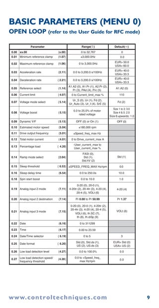
BASIC PARAMETERS (MENU 0)
CONTINUED
0.28 Trip on abnormal load detection {4.29} OFF (0)
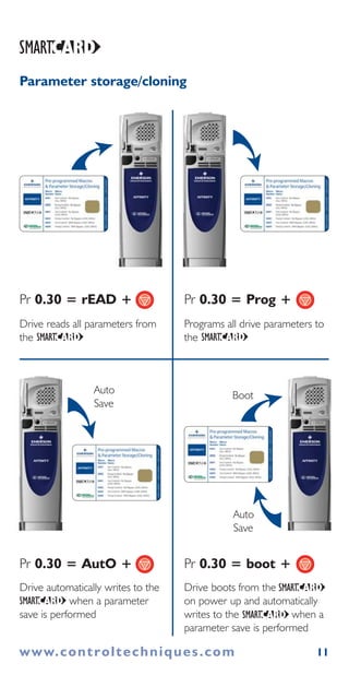
0.29 SMARTCARD parameter data {11.36}
0.30 Parameter cloning {11.42}
nonE (0), rEAd (1), Prog (2),
AutO (3), boot (4)
nonE (0)
0.31 Drive rated voltage {11.33} 200 (0), 400 (1),
575 (2), 690 (3) V
0.32 Drive current scaling {11.32}
0.33 Catch a spinning motor {6.09}
0.34 User security code {11.30}
0.35 PC comms mode {11.24}
0.36 PC comms baud rate {11.25}
300 (0), 600 (1), 1200 (2),
2400 (3), 4800 (4), 9600 (5),
19200 (6), 38400 (7),
Modbus RTU only: 57600 (8),
Modbus RTU only: 115200 (9)
19200 (6)
0.37 PC comms address {11.23}
0.38
Hold zero speed/
Motor pre-heat enable
{6.08}
0.39
Motor pre-heat
current magnitude
{6.52} 0
0.40 Autotune {5.12}
0.41
Maximum switching
frequency
{5.18}
3 (0), 4 (1), 6 (2), 8 (3),
12 (4), 16 (5) kHz
3 (0)
0.42 No. of motor poles {5.11} 0 to 60 (Auto to 120 pole) 0 (Auto)
0.43 Motor rated power factor {5.10}
0.44 Motor rated voltage {5.09}
0 to
AC_voltage_set_max
V
200V drive: 230
400V drive:
EUR> 400,
USA> 460
575V drive: 575
690V drive: 690
0.45
Motor rated full load
speed (rpm)
{5.08}
EUR> 1,500,
USA> 1,800
0.46 Motor rated current {5.07}
0 to
Rated_current_max A
Drive rated
current [11.32]
0.47 Rated frequency {5.06}
EUR> 50.0,
USA> 60.0
0.48 Operating mode selector {11.31} OPEn LP (1), rfc (2) OPEn LP (1)
0.49 Security status {11.44} L1 (0), L2 (1), Loc (2)
0.50 Software version {11.29}
Parameter Default( )Range( )
OFF (0) or On (1)
OFF (0)OFF (0) or On (1)
0 to 999
0.00 to 9999.99A
0
00 to 3
00 to 999
rtu (1)AnSI (0), rtu (1), Lcd (2)
10 to 247
0 to 100%
00 to 2
0.8500.000 to 1.000
0 to 180,000 rpm
0 to 3,000.0 Hz
1.00 to 99.99
0.51 Positive logic select { 8.29} OFF (0) or On (1) On (1)
0.52 Timer 1 start date {9.35} 0 to 311299
0 to 311299
0
0.53 Timer 1 start time {9.36} 0.00 to 23.59 0.00
0.55 Timer 1 stop time {9.38} 0.00 to 23.59 0.00
0.56 Timer 1 repeat function {9.39} 0 to 6 0
0.57 Timer 1 enable {9.40} OFF (0) or On (1) OFF (0)
0.58 Timer 1 destination { 9.40} Pr 0.00 to Pr 50.99 Pr 0.00
0.54 Timer 1 stop date {9.37} 0
www.controltechniques.com](https://image.slidesharecdn.com/affinityquickstartguideissue3-140613205128-phpapp01/85/Affinity-quick-start-guide-issue-3-10-320.jpg)

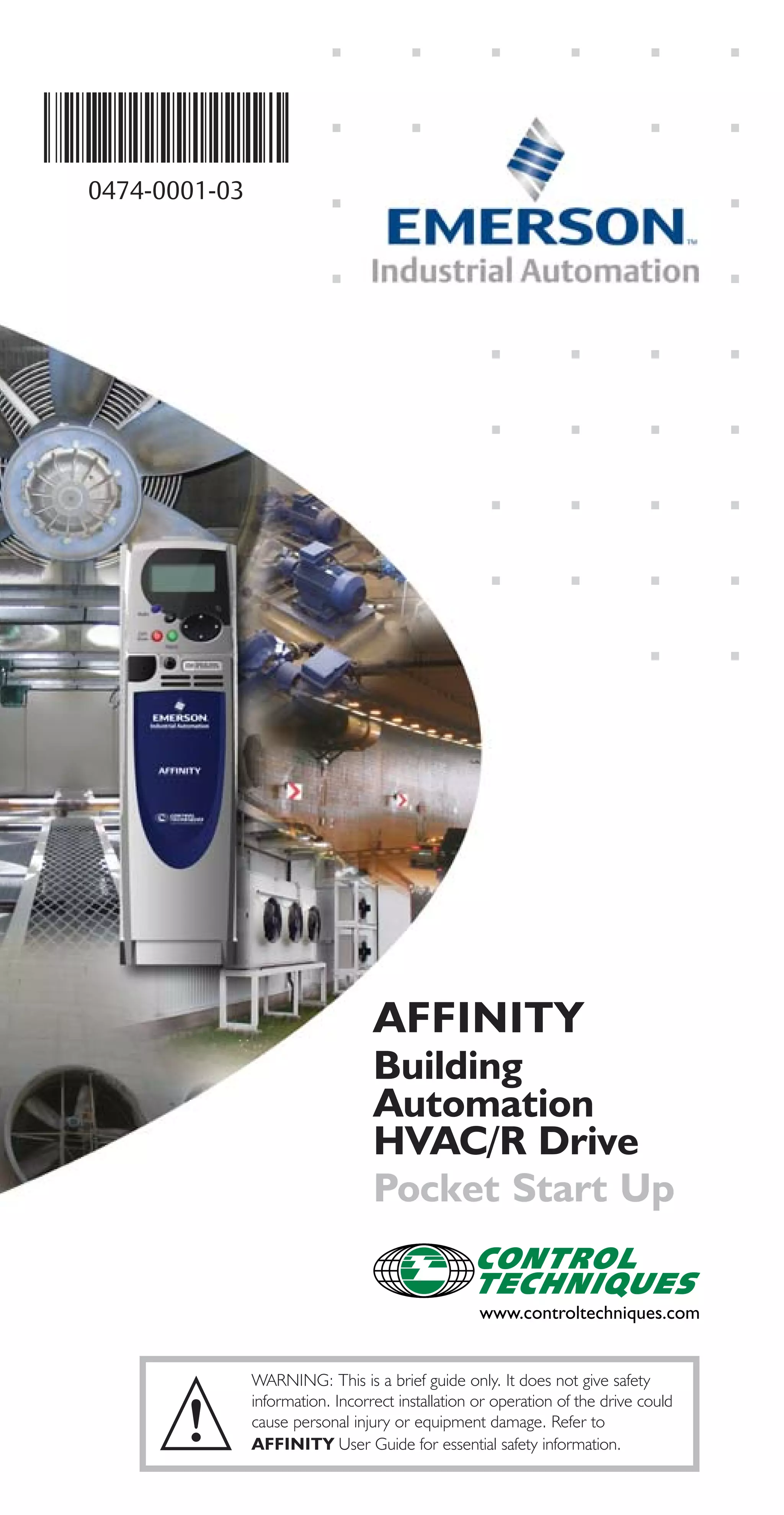
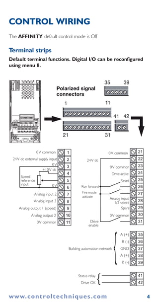
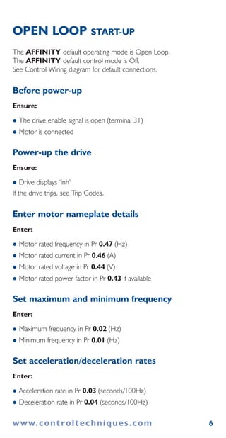
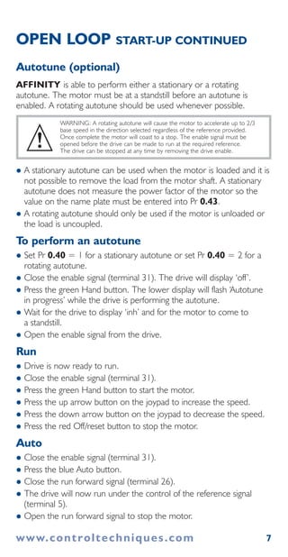
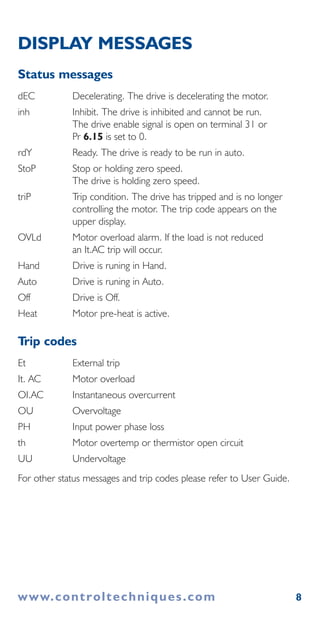
This document provides instructions for installing and starting up an AFFINITY drive in open loop control mode. It includes information on wiring the drive, entering motor parameters, performing autotuning, monitoring status messages, and descriptions of basic adjustable parameters. Safety warnings are given to refer to the full user guide for complete safety information before installing or operating the drive.


![Ct2000 pro plus_manual_english[1]](https://cdn.slidesharecdn.com/ss_thumbnails/ct2000proplusmanualenglish1-140613213527-phpapp02-thumbnail.jpg?width=640&height=640&fit=bounds)


![Ct2000 es manual_english_version_1[1].0](https://cdn.slidesharecdn.com/ss_thumbnails/ct2000esmanualenglishversion11-140613213448-phpapp01-thumbnail.jpg?width=640&height=640&fit=bounds)


