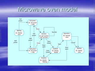
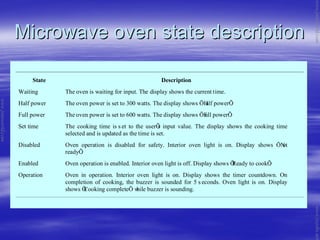
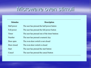
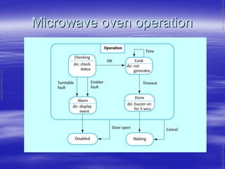
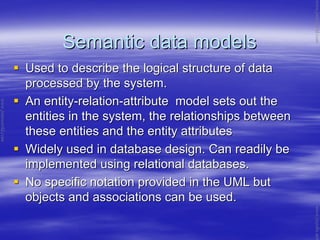
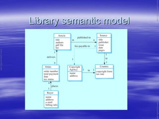
The document discusses system modeling as part of the requirements engineering process. It describes different types of models used to represent systems, including context models, behavioral models, data models, and object models. Specific modeling notations are introduced, such as data flow diagrams, state machines, and entity-relationship diagrams. Examples are provided to illustrate modeling concepts for systems like an ATM, order processing, and a microwave oven. The goal of system modeling is to help analysts understand system functionality from different perspectives to communicate requirements.
The document discusses requirements analysis and analysis modeling principles for software engineering. It covers key topics such as:
1. Requirements analysis specifies a software's operational characteristics and interface with other systems to establish constraints. Analysis modeling focuses on what the software needs to do, not how it will be implemented.
2. Analysis modeling principles include representing the information domain, defining functions, modeling behavior, partitioning complex problems, and moving from essential information to implementation details.
3. Common analysis techniques involve use case diagrams, class diagrams, state diagrams, data flow diagrams, and data modeling to define attributes, relationships, cardinality and modality between data objects.
SE_Lec 05_System Modelling and Context ModelAmr E. Mohamed
System modeling is the process of developing abstract models of a system using graphical notations like the Unified Modeling Language (UML) to represent different views of a system. Models help analysts understand system functionality and communicate with customers. Models of existing and new systems are used during requirements engineering to clarify current systems, discuss strengths/weaknesses, and explain proposed requirements.
Unit 4- Software Engineering System Model Notes arvind pandey
This document discusses system modeling techniques used in software engineering. It covers context models, behavioral models, data models, object models, and CASE workbenches. Different types of models present the system from external, behavioral, and structural perspectives. Common model types include data processing, composition, architectural, and classification models. The document provides examples of context models, state machine models, data flow diagrams, and object models. It also discusses semantic data models, object behavior modeling with sequence diagrams, and components of analysis and design workbenches.
The document discusses static UML diagrams and provides an example of a class diagram for an ATM system. It begins by defining a class diagram and its key components - classes, attributes, operations, and relationships. It then explains different types of class relationships like inheritance, association, aggregation, and composition. The document concludes by providing a full class diagram example for an ATM system to demonstrate how all the concepts discussed come together in a diagram.
The document discusses static UML diagrams, specifically class diagrams. It covers key concepts of classes, attributes, associations, relationships, and notations. It provides examples of class diagrams for conceptual domain models and describes best practices for identifying conceptual classes, attributes, and associations from use case scenarios to build the domain model.
System Models in Software Engineering SE7koolkampus
The document discusses various types of system models used in requirements engineering including context models, behavioral models, data models, object models, and how CASE workbenches support system modeling. It describes behavioral models like data flow diagrams and state machine models, data models like entity-relationship diagrams, and object models using the Unified Modeling Language. CASE tools can support modeling through features like diagram editors, repositories, and code generation.
The Unified Modeling Language (UML) is a general-
purpose, developmental, modeling language in the field
of software engineering, that is intended to provide a
standard way to visualize the design of a system.
Unit 2(advanced class modeling & state diagram)Manoj Reddy
This document discusses state modeling concepts in UML including states, transitions, events, and state diagrams. It provides examples of state diagrams for a phone and traffic lights. States represent conditions an object can be in, such as idle or running. Transitions are changes between states triggered by events like receiving a call. State diagrams visually depict the flow between states.
This document provides an overview of topics covered in Chapter 7 on software design and implementation, including object-oriented design using UML, design patterns, implementation issues, and open source development. It discusses the design and implementation process, build vs buy approaches, object-oriented design processes involving system models, and key activities like defining system context, identifying objects and interfaces. Specific examples are provided for designing a wilderness weather station system.
This chapter discusses system modeling and different types of models used, including:
- Context models which illustrate the operational context of a system.
- Interaction models which model interactions between a system and its environment.
- Structural models which display the organization of a system's components.
- Behavioral models which model a system's dynamic behavior in response to events or data.
- Model-driven engineering is discussed as an approach where models rather than code are the primary outputs.
This document provides an introduction to software engineering. It defines software as a set of instructions that provide desired functions when executed. Engineering is defined as applying scientific methods to construct, operate, modify and maintain useful devices and systems. Software engineering then applies technologies and practices from computer science, project management, and other fields to the design, development and documentation of software. Some key characteristics of software discussed are that it is developed rather than manufactured, can be easily modified and reproduced, and does not wear out. The document also outlines various types of software applications and discusses software engineering as a layered technology with foundations in quality focus, processes, methods and tools. Finally, it addresses some common software myths from management, customer, and practitioner perspectives.
The document provides an overview of object-oriented concepts. It discusses that software development is increasingly relying on object-oriented paradigms due to benefits like improved modeling of real-world problems and reusability. Key concepts discussed include classes and objects, encapsulation, inheritance, polymorphism, and object composition. Various object-oriented methodologies like those proposed by Coad/Yourdon, Booch, Rumbaugh, and Jacobson are also summarized.
This document provides an introduction to software engineering topics including:
1. What software engineering is, its importance, and the software development lifecycle activities it encompasses.
2. The many different types of software systems that exist and how software engineering approaches vary depending on the application.
3. Key fundamentals of software engineering that apply universally, including managing development processes, dependability, and reusing existing software components.
The document provides an overview of the key topics covered in Chapter 4 of the textbook "Software Engineering" related to requirements engineering. It discusses the objectives of requirements engineering, which are to discover and document software requirements through elicitation, analysis, and validation activities. It covers the differences between functional and non-functional requirements, common requirements engineering processes, and techniques for eliciting requirements such as interviews and ethnography. The document also provides examples of requirements for a mental healthcare management system.
The document discusses use case diagrams and use case descriptions for modeling system requirements. It covers drawing use case diagrams to show functional requirements and actors, common mistakes, and writing use case descriptions including basic, alternate, and exception flows of events. The document provides examples and exercises to help understand use cases for requirements modeling.
UML state machine diagrams depict the states an object can be in and the transitions between those states. States are represented by rounded rectangles with transition lines connecting them. Initial states have filled circles while final states have empty circles with dots. Transitions can have triggers, guards, and effects associated with them. Self-transitions allow an object to return to the same state. Superstates group common transitions to simplify diagrams. Compound states include submachine diagrams. Pseudo-states like choices and junctions control transitions. Concurrent regions divide states into concurrently executing parts using fork and join pseudo-states.
This document provides an overview of software reuse techniques discussed in Chapter 16, including:
1) Application frameworks which provide reusable skeleton designs through abstract and concrete classes;
2) Software product lines which allow generic applications to be adapted through configuration, component selection, and specialization for different requirements;
3) COTS (commercial off-the-shelf) product reuse where pre-existing software systems can be customized through deployment configuration without changing source code.
The document discusses software engineering requirements analysis and specification. It covers topics like software requirements types (functional and non-functional), requirement engineering process, feasibility studies, requirements elicitation and analysis. The requirement engineering process involves activities like requirements discovery, analysis, specification, validation and management. It also discusses preparing a software requirements document that defines system specifications.
This ppt covers the object modeling techniques. It has four topics: object model, dynamic model, functional model and the relationship between these models.
Use case diagrams describe interactions between actors and a system to accomplish goals. A use case diagram typically includes:
1) Actors that interact with the system from outside, such as users or other systems. Common actor types are primary actors whose goals are fulfilled by the system and supporting actors that provide services.
2) Use cases that represent functions or tasks performed by the system. They are connected to relevant actors and may have relationships like include and extend.
3) Relationships between use cases like include, which shows a use case incorporating another, and extend, where a use case optionally extends another.
Use case diagrams provide an overview of a system's functions and how outside actors interact with them at a
UML (Unified Modeling Language) is a standard modeling language used to specify, visualize, and document software systems. It uses graphical notations to model structural and behavioral aspects of a system. Common UML diagram types include use case diagrams, class diagrams, sequence diagrams, and state diagrams. Use case diagrams model user interactions, class diagrams show system entities and relationships, sequence diagrams visualize object interactions over time, and state diagrams depict object states and transitions. UML aims to simplify the complex process of software design through standardized modeling.
The document discusses the evolution of client computing from mainframe computers to personal computers and client-server models. It describes the key aspects of mainframe-based computing including its inflexibility and high costs. The rise of personal computers and file sharing networks is outlined. Client-server computing is introduced as having multiple tiers including clients, servers, and middleware to connect them. Common architectures like two-tier, three-tier, and n-tier models are summarized. The benefits of distributed computing models as well as future directions are highlighted.
Ian Sommerville, Software Engineering, 9th Edition Ch1Mohammed Romi
The document provides an introduction to software engineering concepts. It discusses what software engineering is, the importance of ethics in software development, and introduces three case studies that will be used as examples throughout the book. Specifically:
[1] It defines software engineering as an engineering discipline concerned with all aspects of software production. Professional and ethical practices are important.
[2] It discusses software engineering ethics and introduces the ACM/IEEE code of ethics for software engineers.
[3] It provides an overview of three case studies that will be referenced in later chapters: an insulin pump system, a patient management system, and a weather station system.
This document discusses architectural design and software architecture. It covers topics like architectural design decisions, system organization styles, decomposition styles, control styles, and reference architectures. The objectives are to introduce architectural design, explain important decisions, and discuss styles for organizing, decomposing, and controlling systems. Examples and characteristics of different architectural patterns are provided.
This document provides course materials for the subject of Software Quality Management taught in the 8th semester of the Computer Science and Engineering department at A.V.C. College of Engineering in Mannampandal, India. It includes the syllabus, course objectives, textbook information, and an introductory section on fundamentals of software quality covering topics like hierarchical quality models, quality measurement, and metrics.
Object Oriented Design in Software Engineering SE12koolkampus
The document discusses object-oriented design (OOD) and describes its key characteristics and processes. Specifically, it covers:
1) Objects communicate by message passing and are self-contained entities that encapsulate state and behavior.
2) The OOD process involves identifying objects and classes, defining their interfaces, relationships, and developing models of the system.
3) The Unified Modeling Language (UML) is used to describe OOD models including classes, objects, associations, and other relationships.
The document discusses different types of system models used in requirements engineering including context models, behavioral models, data models, and object models. It describes modeling the system's behavior using data flow diagrams and state machine diagrams. The document also introduces the Unified Modeling Language (UML) and how computer-aided software engineering (CASE) tools can support system modeling.
The document outlines the software requirements engineering process, which includes gathering requirements from stakeholders, documenting them in a software requirements specification (SRS), and validating the requirements. It discusses the different types of requirements like functional, non-functional, and domain requirements. It also describes various techniques used for eliciting requirements, such as interviews, surveys, questionnaires, task analysis, domain analysis, brainstorming, and prototyping.
This document contains slides from a lecture on operating system concepts including swapping, contiguous memory allocation, paging, segmentation, and page replacement. It discusses key topics such as logical vs physical addresses, page tables, translation lookaside buffers, demand paging, and page faults. The document includes 10 slides with diagrams and explanations of these operating system memory management techniques.
This is our Object Oriented Programme course presentation slide which was compeletly made by me.I think it will help others to clear their concept about this.
The document discusses the process of designing view layer classes in a user interface. It involves:
1) Identifying view layer objects during analysis by examining use cases and interaction diagrams.
2) Designing individual view layer objects by applying design principles like simplicity and usability testing.
3) Iteratively refining the design by getting feedback and making improvements.
Unt 3 attributes, methods, relationships-1gopal10scs185
This document discusses different types of relationships in object-oriented modeling: association, generalization (super-substructure), and aggregation. Association represents a connection between objects and can be binary, ternary, or higher-order. Generalization shows inheritance relationships in a hierarchy. Aggregation represents a "part-of" relationship where a class contains other component classes.
The document discusses architectural UML and provides information on:
1) The elements of a software architecture including views, models, and diagrams.
2) How UML can be used to represent different architectural views including design, process, development, and physical views.
3) An example of using UML models and diagrams to represent different views of a chess game architecture.
This document discusses designing classes in object-oriented design. It covers designing class attributes and methods, class visibility including private, protected, and public protocols, refining class attributes with data types and initial values, designing methods using activity diagrams, avoiding pitfalls like overly large classes, and presenting classes using UML notation. The goal is to design well-structured, reusable classes through an iterative refinement process.
This document discusses usability testing and measuring user satisfaction. It defines usability as the effectiveness, efficiency and satisfaction with which users can complete tasks. Usability testing measures ease of use and user comfort/satisfaction, and should begin early in development. Guidelines are provided for developing usability and user satisfaction test cases and recording usability tests. User satisfaction testing quantifies usability with measurable attributes and objectives include communication between designers and users.
This document provides an overview of object-oriented analysis and design concepts. It defines key OO terms like objects, classes, inheritance, polymorphism, and relationships. It also describes several OO methodologies like OMT, Booch, and Objectory. Finally, it discusses design patterns, frameworks, and the motivation for a unified OO approach.
System model.Chapter One(GEOFFREY GORDON)Towfiq218
This document provides an overview of system modeling concepts. It defines what a system is and basic system components like entities, attributes, and activities. It discusses different types of systems like open vs closed systems, stochastic vs deterministic activities, and continuous vs discrete systems. It also covers various types of models like physical, mathematical, static, and dynamic models. Specific examples are provided to illustrate concepts like static and dynamic physical and mathematical models. Principles of modeling like block-building, relevance, accuracy, and aggregation are also covered.
Unit 4 discusses object oriented design processes and axioms. The key points are:
1. The object oriented design process involves defining classes, methods, attributes and associations, applying design axioms to refine UML diagrams, and testing design through prototypes and use cases.
2. There are two main axioms - maintaining independence of components and minimizing information content.
3. Corollaries derived from the axioms include uncoupled design with less information, single purpose classes, large number of small reusable classes, strong mapping from analysis to implementation, standardization, and inheritance-based design.
The document discusses different approaches for identifying classes during object analysis, including the noun phrase approach, common class patterns approach, use case driven approach, and Classes, Responsibilities, and Collaborators (CRC) approach. It provides guidelines for selecting classes, naming classes, identifying attributes versus classes, and an example of applying the noun phrase approach to identify initial classes for a bank ATM system.
The objective is to explain how a software design may be represented as a set of interacting objects that manage their own state and operations and to introduce various models that describe an object-oriented design.
Object-oriented analysis and design (OOAD) is a popular approach for analyzing, designing, and developing applications using the object-oriented paradigm. It involves modeling a system as a group of interacting objects at various levels of abstraction. Key concepts in OOAD include objects, classes, attributes, methods, encapsulation, inheritance, polymorphism, and relationships like association, aggregation, and composition. Common OOAD techniques include use case diagrams, which show interactions between actors and the system, and class diagrams, which describe the structure and behavior of system objects and their relationships.
The document discusses the Unified Modeling Language (UML) which is a general-purpose modeling language used to visualize, specify, construct, and document software systems. UML uses graphical notation to represent the design of software projects including concepts like use case diagrams, class diagrams, sequence diagrams, and more. It provides a standard way to visualize a system from different perspectives including structural and behavioral views.
Rumbaugh's Object Modeling Technique (OMT) is an object-oriented analysis and design methodology. It uses three main modeling approaches: object models, dynamic models, and functional models. The object model defines the structure of objects in the system through class diagrams. The dynamic model describes object behavior over time using state diagrams and event flow diagrams. The functional model represents system processes and data flow using data flow diagrams.
The document discusses several models of consumer behaviour, including Lawson's model of buying behaviour, factors that influence consumer behaviour, and the buyer decision process. It also covers behaviourist and cognitivist theories of consumer behaviour, and discusses models like the Engel-Kollat-Blackwell model, Howard & Sheth model, and Maslow's hierarchy of needs model.
UML (Unified Modeling Language) is a standard language for specifying, visualizing, constructing and documenting software systems. It uses mainly graphical notations to express design of software projects. There are two main categories of UML diagrams - structural diagrams which focus on static elements regardless of time, and behavioral diagrams which focus on dynamic features and business processes. Common UML diagram types include class, sequence, use case, activity, state machine, component, deployment and interaction diagrams.
This document provides an overview of object-oriented analysis and design. It defines key terms and concepts in object-oriented modeling like use cases, class diagrams, states, sequences. It describes developing requirements models using use cases and class diagrams. It also explains modeling object behavior through state and sequence diagrams and transitioning analysis models to design.
This document provides an overview of system modeling. It discusses that system modeling involves developing abstract models of a system from different perspectives, and is commonly done using the Unified Modeling Language (UML). It also describes various UML diagram types used in system modeling like use case diagrams, class diagrams, and state diagrams. Finally, it gives examples of modeling different views of a mental health case management system, including contextual models, interaction models, structural models, and behavioral models.
System modeling involves developing abstract models of a system from different perspectives using notations like UML. Models are used during requirements, design, and documentation. Common model types include context models, interaction models using use cases and sequence diagrams, structural class diagrams, and behavioral state diagrams. Model-driven engineering aims to generate implementations automatically from models. Key aspects of software design include understanding interactions, architectural design, identifying objects, developing design models, and specifying interfaces. Design patterns provide reusable solutions to common problems.
System modeling is the process of developing abstract models of a system using graphical notations like UML. System models present different views or perspectives of a system, such as external context, interactions, structure, and behavior. Common UML diagram types used in system modeling include use case diagrams, sequence diagrams, class diagrams, and state diagrams. System modeling helps analysts understand system functionality and communicate with customers.
Software engineering ,system modeing >>Abu ul hassan sahadviAbuulHassan2
System modeling involves developing abstract models of a system from different perspectives to help understand its functionality. Common modeling techniques include use case diagrams, which show interactions between a system and external actors, and class diagrams, which define the system's classes and their relationships. Behavioral models depict how a system responds to stimuli over time through states and transitions. System modeling aids communication and ensures requirements and design match customer needs.
System models abstractly describe systems being analyzed and are used to communicate with customers. Different models show the system from external, behavioral, and structural perspectives. Common system models include context models depicting system boundaries, data flow diagrams modeling data processing, state machine models representing system states and transitions, and object models describing the system in terms of object classes and relationships. The Unified Modeling Language provides standard notations for object-oriented modeling.
The document discusses various modeling techniques used in requirements analysis for web applications (WebApps), including:
1) Content modeling to identify and describe all content objects and their relationships.
2) Interaction modeling using use cases, sequence diagrams, state diagrams, and prototypes to describe how users interact.
3) Functional modeling to define all necessary operations and processing functions implied by usage scenarios.
The techniques help analysts understand WebApp requirements by modeling key elements like content, interactions, and functions.
Modeling and simulation is the use of models as a basis for simulations to develop data utilized for managerial or technical decision making. In the computer application of modeling and simulation a computer is used to build a mathematical model which contains key parameters of the physical model.
The document discusses different types of system models used in requirements engineering including context models, behavioral models, data models, and object models. It describes modeling the system's context, data processing, behavior in response to events, logical data structure, and objects. The document also introduces the Unified Modeling Language (UML) and how computer-aided software engineering (CASE) workbenches support system modeling.
The document discusses different types of system models used in requirements engineering, including context models, behavioral models, data models, and object models. It provides examples of each type of model, such as a data flow diagram of an order processing system and a state diagram for a microwave oven. The objectives are to explain why system context should be modeled, describe different modeling notations and perspectives, and discuss how computer-aided software engineering tools can support system modeling.
The document discusses use cases and use case diagrams. It defines a use case as a description of a set of sequences of actions that a system performs to yield an observable result for an actor. Actors can be human users or other systems. Use cases specify what a system does without specifying how. Relationships like generalization, inclusion, and extension are used to organize use cases. A use case diagram visually depicts the actors and their interactions with the system's use cases.
1 MODULE 1 INTRODUCTION TO SIMULATION Module out.docxjeremylockett77
1
MODULE 1: INTRODUCTION TO SIMULATION
Module outline:
• What is Simulation?
• Simulation Terminology
• Components of a System
• Models in Simulation
• Typical applications
• References
WHAT IS SIMULATION?
simulation may be defined as a technique that imitates the operation of a real world
system or processes as it evolves over time. It involves the generation of an artificial
history of the system and observation of that artificial history to obtain information and
draw inferences about the operating characteristics of the real system. Simulation
educates us on how a system operates and how the system might respond to changes. It
enables us to test alternative courses of action to determine their impact on system
performance. Before an alternative is implemented, it must be tested. Although
performing tests with the “real thing” would be ideal. This is seldom practically feasible.
The cost associated with changing/improving a system may be very high both in the
term of capital required to implement the change and losses due to interruption in
production operations and other losses. In most cases experimentation with the
proposed alternative is practically impossible. In addition, as the cost of proposed
changes (alternative solutions) increase, so does the cost of physically experimenting.
As an example, suppose a heavy-duty conveyor is being considered as an alternative to
the existing material handling method (by trucks) for improving productivity and
speeding up the production operations in a factory (seeFigre3). It is obvious that
installing the proposed conveyor on a test basis would probably not be cost effective.
Therefore, experimentation with alternative configurations would be practically
impossible. In stead, experimentation with a representative model of the system would
probably make more sense.
Simulation is a means of experimenting with a detailed model of a real system to
Determine how the system will respond to changes in its environment, structure, and its
underlying assumption [Harrel (1996)]. Management Scientist uses a wide variety of
analytical tools to model, analyze, and solve complex decision problems. These tool
include linear programming, decision analysis, forecasting, Queuing theory and
Alternative 1: Use lift-truck
2
Point A Point B
(Warehouse) (Factory)
Alternative 2: use a conveyor
Point A
(warehouse ) . . . . . . . . Point B
...
Object-oriented analysis and design (OOAD) uses visual modeling techniques like the Unified Modeling Language (UML) to analyze and design systems based on interacting objects. UML captures system elements and facilitates specification and visualization. It includes static diagrams for non-changing characteristics and dynamic diagrams for changing behaviors. The goal of OOAD and UML is to integrate analysis and development teams through defined processes and modeling.
Introduction to simulation and modeling will describe what is simulation, what is system and what is model. It will give a brief overview of simulation and modeling in computer science.
The document discusses system modeling and different types of models used during requirements engineering including context models, data flow diagrams, state machine models, semantic data models, object models, and sequence diagrams. It also introduces the Unified Modeling Language (UML) notation and explains how analysis workbenches can support system modeling.
This document discusses system modeling and provides examples from a patient management system (MHC-PMS). It describes using different types of models to represent a system from various perspectives, including context models to illustrate the system's operational environment, interaction models like use case and sequence diagrams to show user interactions, and structural and behavioral models. Specific MHC-PMS models are presented, such as a context diagram depicting related systems, use cases for medical receptionist roles, and sequence diagrams for user tasks like viewing patient information. The key points are that complementary system models abstractly represent a system from different viewpoints like context, interactions, structure, and behavior.
This document discusses system modeling and provides examples from a patient management system (MHC-PMS). It describes using different types of models to represent a system from various perspectives, including context models to illustrate the system's operational environment, interaction models like use case and sequence diagrams to show user interactions, and structural and behavioral models. Specific MHC-PMS models are presented, such as a context diagram depicting related systems, use cases for medical receptionist roles, and sequence diagrams for user flows like viewing patient information. The key points are that complementary system models abstractly represent a system from different viewpoints like context, interactions, structure, and behavior.
Lab 3 Introduction to the UML - how to create a use case diagramFarah Ahmed
The document discusses use case diagrams and use case modeling. It provides an overview of use case diagrams, including their purpose and components. Key points include:
- Use case diagrams show interactions between actors and the system/software being modeled through use cases. They are used early in development to capture requirements and later to specify system behavior.
- Components of a use case diagram include actors, use cases, and relationships between them like generalization, include, and extend. Actors represent roles that interact with the system while use cases represent system functions/processes.
- Examples of a use case diagram for a vehicle sales system are provided to demonstrate how actors, use cases, and relationships can be modeled visually. Guidance is
1. The document discusses various software engineering process models including waterfall, prototyping, RAD, incremental, and spiral models. It describes the key phases and advantages/disadvantages of each.
2. It also covers system engineering and how software engineering occurs as part of developing larger systems. Business process engineering and product engineering are introduced for developing information systems and products respectively.
3. Key aspects of developing computer-based systems are outlined including the elements of software, hardware, people, databases, documentation and procedures.
The document discusses various aspects of risk management for projects. It describes reactive risk management where risks are addressed after occurring versus proactive risk management where formal risk analysis is performed upfront. It identifies different types of project risks and provides questions to assess risks due to factors like product size, business impact, customers, and development processes. Overall project risk management involves identifying, analyzing, planning for, and tracking risks.
This document discusses various metrics for measuring software quality and object-oriented design. It introduces McCall's quality factors triangle and describes measures, metrics, and indicators. It then discusses principles of software measurement and the measurement process. It provides examples of function-based metrics, architectural design metrics, object-oriented design metrics, and class-oriented metrics. The document aims to define different metrics and provide guidance on applying them to assess software quality.
This document discusses process and project metrics for software development. It explains that metrics are used to measure the status of ongoing projects, track risks, uncover problems, and evaluate quality. Process metrics indirectly measure the efficacy of the software development process by looking at outcomes like errors, defects, productivity, effort, and schedule adherence. Project metrics are used to minimize schedules and assess ongoing product quality. Typical metrics include effort per task, errors per review hour, and milestone dates. The document provides guidelines for using metrics and discusses different types of metrics like size-oriented, function-oriented, and object-oriented metrics.
The document discusses various techniques for software testing, including testability, what constitutes a "good" test, test case design, exhaustive vs selective testing, white-box vs black-box testing, and basis path testing. Basis path testing involves determining the cyclomatic complexity of a program's control flow graph to identify the minimum number of independent paths that need to be tested to achieve full coverage. Test cases are then designed to execute each basis path.
The document discusses software testing strategies. It covers topics like test strategy, test planning, test case design, test execution, verification and validation, unit testing, integration testing, object-oriented testing, validation testing, debugging, and consequences of bugs. The overall strategy is to begin with unit testing, then conduct integration testing by integrating modules, followed by system and validation testing to ensure requirements are met.
The document discusses object-oriented design (OOD). It aims to explain how a software design can be represented as interacting objects that manage their own state and operations. It describes the activities in the OOD process and introduces models that can be used, including the Unified Modeling Language (UML). Characteristics of OOD like encapsulation and message passing are covered. The document provides examples of concepts like objects, classes, associations, generalization and inheritance. It also discusses design of concurrent and distributed systems.
The document discusses user interface design. It covers analyzing users and tasks, designing interfaces that are easy to use, consistent and put users in control. Interface design involves understanding users, tasks and content before defining objects, actions and states. Patterns can guide layout, forms and navigation. Evaluation ensures the interface is responsive, helpful and handles errors well. The goal is an interface that is easy to understand, learn and consistent.
The document discusses the benefits of meditation for reducing stress and anxiety. Regular meditation practice can help calm the mind and body by lowering heart rate and blood pressure. Making meditation a part of a daily routine, even if just 10-15 minutes per day, can offer improvements to mood, focus, and overall well-being over time.
The document discusses concepts related to design engineering and software design quality. It covers topics like the analysis model and design model, design and quality guidelines, abstraction, architecture, patterns, modularity, information hiding, functional independence, refinement, refactoring, object-oriented design concepts, and the design model process dimension. Key points include that design should implement requirements, be readable and guide implementation, and address data, functional and behavioral domains. Design quality is achieved through recognizable architectural styles, components with good characteristics, and evolutionary implementation.
Unit 3 requirements engineering processesAzhar Shaik
This document discusses requirements engineering processes. It covers topics like feasibility studies, requirements elicitation and analysis, requirements validation, and requirements management. The key activities in requirements engineering are requirements elicitation, analysis, validation, and management. Requirements engineering involves interacting with stakeholders to understand system needs and documenting requirements. Techniques like interviews, prototyping and reviews are used to validate requirements.
The document discusses several process models for software development including the waterfall model, prototyping model, spiral model, incremental model, RAD model, and unified process. The waterfall model is a linear sequential model moving down in distinct phases from conception to maintenance. The prototyping model emphasizes early customer feedback through quick building of prototypes. The spiral model combines elements of the waterfall model and prototyping model with each cycle of the spiral representing a single iteration of requirements, design, coding, and testing.
Unit 2 analysis and software requirementsAzhar Shaik
The document discusses software requirements and requirements analysis. It introduces the concepts of user and system requirements and describes functional and non-functional requirements. It explains how requirements can be organized in a requirements specification document. The document outlines various topics related to requirements including problem analysis techniques, requirement specification, the components and format of a Software Requirements Specification, characteristics of a good SRS, validation methods, and the differences between functional and non-functional requirements.
This document did not contain any text to summarize. A summary requires content in order to extract the key ideas and essential information in 3 sentences or less.
The document discusses software and software engineering. It defines software as a collection of computer programs, procedures, and associated documentation and data. Software engineering is defined as the systematic approach to developing, operating, and maintaining software. The document also discusses different types of software applications and categories, the evolution of software over time, software process frameworks, and models for personal and team software processes.
Beyond Degrees - Empowering the Workforce in the Context of Skills-First.pptxEduSkills OECD
Iván Bornacelly, Policy Analyst at the OECD Centre for Skills, OECD, presents at the webinar 'Tackling job market gaps with a skills-first approach' on 12 June 2024
Walmart Business+ and Spark Good for Nonprofits.pdfTechSoup
"Learn about all the ways Walmart supports nonprofit organizations.
You will hear from Liz Willett, the Head of Nonprofits, and hear about what Walmart is doing to help nonprofits, including Walmart Business and Spark Good. Walmart Business+ is a new offer for nonprofits that offers discounts and also streamlines nonprofits order and expense tracking, saving time and money.
The webinar may also give some examples on how nonprofits can best leverage Walmart Business+.
The event will cover the following::
Walmart Business + (https://business.walmart.com/plus) is a new shopping experience for nonprofits, schools, and local business customers that connects an exclusive online shopping experience to stores. Benefits include free delivery and shipping, a 'Spend Analytics” feature, special discounts, deals and tax-exempt shopping.
Special TechSoup offer for a free 180 days membership, and up to $150 in discounts on eligible orders.
Spark Good (walmart.com/sparkgood) is a charitable platform that enables nonprofits to receive donations directly from customers and associates.
Answers about how you can do more with Walmart!"
ISO/IEC 27001, ISO/IEC 42001, and GDPR: Best Practices for Implementation and...PECB
Denis is a dynamic and results-driven Chief Information Officer (CIO) with a distinguished career spanning information systems analysis and technical project management. With a proven track record of spearheading the design and delivery of cutting-edge Information Management solutions, he has consistently elevated business operations, streamlined reporting functions, and maximized process efficiency.
Certified as an ISO/IEC 27001: Information Security Management Systems (ISMS) Lead Implementer, Data Protection Officer, and Cyber Risks Analyst, Denis brings a heightened focus on data security, privacy, and cyber resilience to every endeavor.
His expertise extends across a diverse spectrum of reporting, database, and web development applications, underpinned by an exceptional grasp of data storage and virtualization technologies. His proficiency in application testing, database administration, and data cleansing ensures seamless execution of complex projects.
What sets Denis apart is his comprehensive understanding of Business and Systems Analysis technologies, honed through involvement in all phases of the Software Development Lifecycle (SDLC). From meticulous requirements gathering to precise analysis, innovative design, rigorous development, thorough testing, and successful implementation, he has consistently delivered exceptional results.
Throughout his career, he has taken on multifaceted roles, from leading technical project management teams to owning solutions that drive operational excellence. His conscientious and proactive approach is unwavering, whether he is working independently or collaboratively within a team. His ability to connect with colleagues on a personal level underscores his commitment to fostering a harmonious and productive workplace environment.
Date: May 29, 2024
Tags: Information Security, ISO/IEC 27001, ISO/IEC 42001, Artificial Intelligence, GDPR
-------------------------------------------------------------------------------
Find out more about ISO training and certification services
Training: ISO/IEC 27001 Information Security Management System - EN | PECB
ISO/IEC 42001 Artificial Intelligence Management System - EN | PECB
General Data Protection Regulation (GDPR) - Training Courses - EN | PECB
Webinars: https://pecb.com/webinars
Article: https://pecb.com/article
-------------------------------------------------------------------------------
For more information about PECB:
Website: https://pecb.com/
LinkedIn: https://www.linkedin.com/company/pecb/
Facebook: https://www.facebook.com/PECBInternational/
Slideshare: http://www.slideshare.net/PECBCERTIFICATION
Level 3 NCEA - NZ: A Nation In the Making 1872 - 1900 SML.pptHenry Hollis
The History of NZ 1870-1900.
Making of a Nation.
From the NZ Wars to Liberals,
Richard Seddon, George Grey,
Social Laboratory, New Zealand,
Confiscations, Kotahitanga, Kingitanga, Parliament, Suffrage, Repudiation, Economic Change, Agriculture, Gold Mining, Timber, Flax, Sheep, Dairying,
Philippine Edukasyong Pantahanan at Pangkabuhayan (EPP) CurriculumMJDuyan
(𝐓𝐋𝐄 𝟏𝟎𝟎) (𝐋𝐞𝐬𝐬𝐨𝐧 𝟏)-𝐏𝐫𝐞𝐥𝐢𝐦𝐬
𝐃𝐢𝐬𝐜𝐮𝐬𝐬 𝐭𝐡𝐞 𝐄𝐏𝐏 𝐂𝐮𝐫𝐫𝐢𝐜𝐮𝐥𝐮𝐦 𝐢𝐧 𝐭𝐡𝐞 𝐏𝐡𝐢𝐥𝐢𝐩𝐩𝐢𝐧𝐞𝐬:
- Understand the goals and objectives of the Edukasyong Pantahanan at Pangkabuhayan (EPP) curriculum, recognizing its importance in fostering practical life skills and values among students. Students will also be able to identify the key components and subjects covered, such as agriculture, home economics, industrial arts, and information and communication technology.
𝐄𝐱𝐩𝐥𝐚𝐢𝐧 𝐭𝐡𝐞 𝐍𝐚𝐭𝐮𝐫𝐞 𝐚𝐧𝐝 𝐒𝐜𝐨𝐩𝐞 𝐨𝐟 𝐚𝐧 𝐄𝐧𝐭𝐫𝐞𝐩𝐫𝐞𝐧𝐞𝐮𝐫:
-Define entrepreneurship, distinguishing it from general business activities by emphasizing its focus on innovation, risk-taking, and value creation. Students will describe the characteristics and traits of successful entrepreneurs, including their roles and responsibilities, and discuss the broader economic and social impacts of entrepreneurial activities on both local and global scales.
2. ObjectivesObjectives
To explain why the context of a systemTo explain why the context of a system
should be modelled as part of the REshould be modelled as part of the RE
processprocess
To describe behavioural modelling, dataTo describe behavioural modelling, data
modelling and object modellingmodelling and object modelling
To introduce some of the notations used inTo introduce some of the notations used in
the Unified Modeling Language (UML)the Unified Modeling Language (UML)
To show how CASE workbenches supportTo show how CASE workbenches support
system modellingsystem modelling
www.jntuworld.com
www.jntuworld.com
www.jwjobs.net
4. System modellingSystem modelling
System modelling helps the analyst to understandSystem modelling helps the analyst to understand
the functionality of the system and models arethe functionality of the system and models are
used to communicate with customers.used to communicate with customers.
Different models present the system from differentDifferent models present the system from different
perspectivesperspectives
–– External perspective showing the systemExternal perspective showing the system’’s context ors context or
environment;environment;
–– Behavioural perspective showing the behaviour of theBehavioural perspective showing the behaviour of the
system;system;
–– Structural perspective showing the system or dataStructural perspective showing the system or data
architecture.architecture.
www.jntuworld.com
www.jntuworld.com
www.jwjobs.net
5. Model typesModel types
Data processing model showing how the dataData processing model showing how the data
is processed at different stages.is processed at different stages.
Composition model showing how entities areComposition model showing how entities are
composed of other entities.composed of other entities.
Architectural model showing principal subArchitectural model showing principal sub--
systems.systems.
Classification model showing how entitiesClassification model showing how entities
have common characteristics.have common characteristics.
Stimulus/response model showing theStimulus/response model showing the
systemsystem’’s reaction to events.s reaction to events.
www.jntuworld.com
www.jntuworld.com
www.jwjobs.net
6. Context modelsContext models
Context models are used to illustrate theContext models are used to illustrate the
operational context of a systemoperational context of a system -- they showthey show
what lies outside the system boundaries.what lies outside the system boundaries.
Social and organisational concerns maySocial and organisational concerns may
affect the decision on where to positionaffect the decision on where to position
system boundaries.system boundaries.
Architectural models show the system andArchitectural models show the system and
its relationship with other systems.its relationship with other systems.
www.jntuworld.com
www.jntuworld.com
www.jwjobs.net
7. The context of an ATM systemThe context of an ATM system
www.jntuworld.com
www.jntuworld.com
www.jwjobs.net
8. Process modelsProcess models
Process models show the overall processProcess models show the overall process
and the processes that are supported by theand the processes that are supported by the
system.system.
Data flow models may be used to show theData flow models may be used to show the
processes and the flow of information fromprocesses and the flow of information from
one process to another.one process to another.
www.jntuworld.com
www.jntuworld.com
www.jwjobs.net
10. Behavioural modelsBehavioural models
Behavioural models are used to describeBehavioural models are used to describe
the overall behaviour of a system.the overall behaviour of a system.
Two types of behavioural model are:Two types of behavioural model are:
–– Data processing models that show how data isData processing models that show how data is
processed as it moves through the system;processed as it moves through the system;
–– State machine models that show the systemsState machine models that show the systems
response to events.response to events.
These models show different perspectivesThese models show different perspectives
so both of them are required to describe theso both of them are required to describe the
systemsystem’’s behaviour.s behaviour.
www.jntuworld.com
www.jntuworld.com
www.jwjobs.net
11. DataData--processing modelsprocessing models
Data flow diagrams (DFDs) may be used toData flow diagrams (DFDs) may be used to
model the systemmodel the system’’s data processing.s data processing.
These show the processing steps as dataThese show the processing steps as data
flows through a system.flows through a system.
DFDs are an intrinsic part of many analysisDFDs are an intrinsic part of many analysis
methods.methods.
Simple and intuitive notation that customersSimple and intuitive notation that customers
can understand.can understand.
Show endShow end--toto--end processing of data.end processing of data.
www.jntuworld.com
www.jntuworld.com
www.jwjobs.net
13. Data flow diagramsData flow diagrams
DFDs model the system from a functionalDFDs model the system from a functional
perspective.perspective.
Tracking and documenting how the dataTracking and documenting how the data
associated with a process is helpful toassociated with a process is helpful to
develop an overall understanding of thedevelop an overall understanding of the
system.system.
Data flow diagrams may also be used inData flow diagrams may also be used in
showing the data exchange between ashowing the data exchange between a
system and other systems in itssystem and other systems in its
environment.environment.
www.jntuworld.com
www.jntuworld.com
www.jwjobs.net
15. State machine modelsState machine models
These model the behaviour of the system inThese model the behaviour of the system in
response to external and internal events.response to external and internal events.
They show the systemThey show the system’’s responses to stimuli sos responses to stimuli so
are often used for modelling realare often used for modelling real--time systems.time systems.
State machine models show system states asState machine models show system states as
nodes and events as arcs between these nodes.nodes and events as arcs between these nodes.
When an event occurs, the system moves fromWhen an event occurs, the system moves from
one state to another.one state to another.
Statecharts are an integral part of the UML andStatecharts are an integral part of the UML and
are used to represent state machine models.are used to represent state machine models.
www.jntuworld.com
www.jntuworld.com
www.jwjobs.net
16. StatechartsStatecharts
Allow the decomposition of a model intoAllow the decomposition of a model into
subsub--models (see following slide).models (see following slide).
A brief description of the actions is includedA brief description of the actions is included
following thefollowing the ‘‘dodo’’ in each state.in each state.
Can be complemented by tables describingCan be complemented by tables describing
the states and the stimuli.the states and the stimuli.
www.jntuworld.com
www.jntuworld.com
www.jwjobs.net
18. Microwave oven state descriptionMicrowave oven state description
State Description
Waiting The oven is waiting for input. The display shows the current time.
Half power The oven power is set to 300 watts. The display shows ŌHalf powerÕ.
Full power The oven power is set to 600 watts. The display shows ŌFull powerÕ.
Set time The cooking time is s et to the userÕs input value. The display shows the cooking time
selected and is updated as the time is set.
Disabled Oven operation is disabled for safety. Interior oven light is on. Display shows ŌNot
readyÕ.
Enabled Oven operation is enabled. Interior oven light is off. Display shows ŌReady to cookÕ.
Operation Oven in operation. Interior oven light is on. Display shows the timer countdown. On
completion of cooking, the buzzer is sounded for 5 s econds. Oven light is on. Display
shows ŌCooking completeÕ while buzzer is sounding.
www.jntuworld.com
www.jntuworld.com
www.jwjobs.net
19. Microwave oven stimuliMicrowave oven stimuli
Stimulus Description
Half power The user has pressed the half power button
Full power The user has pressed the full power button
Timer The user has pressed one of the timer buttons
Number The user has pressed a numeric key
Door open The oven door switch is not closed
Door closed The oven door switch is closed
Start The user has pressed the start button
Cancel The user has pressed the cancel button
www.jntuworld.com
www.jntuworld.com
www.jwjobs.net
21. Semantic data modelsSemantic data models
Used to describe the logical structure of dataUsed to describe the logical structure of data
processed by the system.processed by the system.
An entityAn entity--relationrelation--attribute model sets out theattribute model sets out the
entities in the system, the relationships betweenentities in the system, the relationships between
these entities and the entity attributesthese entities and the entity attributes
Widely used in database design. Can readily beWidely used in database design. Can readily be
implemented using relational databases.implemented using relational databases.
No specific notation provided in the UML butNo specific notation provided in the UML but
objects and associations can be used.objects and associations can be used.
www.jntuworld.com
www.jntuworld.com
www.jwjobs.net
23. Data dictionariesData dictionaries
Data dictionaries are lists of all of the names usedData dictionaries are lists of all of the names used
in the system models. Descriptions of the entities,in the system models. Descriptions of the entities,
relationships and attributes are also included.relationships and attributes are also included.
AdvantagesAdvantages
–– Support name management and avoid duplication;Support name management and avoid duplication;
–– Store of organisational knowledge linking analysis,Store of organisational knowledge linking analysis,
design and implementation;design and implementation;
Many CASE workbenches support dataMany CASE workbenches support data
dictionaries.dictionaries.
www.jntuworld.com
www.jntuworld.com
www.jwjobs.net
24. Data dictionary entriesData dictionary entries
Name Description Type Date
Article
Details of the published article that may be ordered by
people using LIBSYS.
Entity 30.12.2002
authors
The names of the authors of the article who may be due
a share of the fee.
Attribute 30.12.2002
Buyer
The person or organisation that orders a co py of the
article.
Entity 30.12.2002
fee-
payable-to
A 1:1 relationship between Article and the Copyright
Agency who should be paid the copyright fee.
Relation 29.12.2002
Address
(Buyer)
The address of the buyer. This is used to any paper
billing information that is required.
Attribute 31.12.2002
www.jntuworld.com
www.jntuworld.com
www.jwjobs.net
25. Object modelsObject models
Object models describe the system in terms ofObject models describe the system in terms of
object classes and their associations.object classes and their associations.
An object class is an abstraction over a set ofAn object class is an abstraction over a set of
objects with common attributes and the servicesobjects with common attributes and the services
(operations) provided by each object.(operations) provided by each object.
Various object models may be producedVarious object models may be produced
–– Inheritance models;Inheritance models;
–– Aggregation models;Aggregation models;
–– Interaction models.Interaction models.
www.jntuworld.com
www.jntuworld.com
www.jwjobs.net
26. Object modelsObject models
Natural ways of reflecting the realNatural ways of reflecting the real--worldworld
entities manipulated by the systementities manipulated by the system
More abstract entities are more difficult toMore abstract entities are more difficult to
model using this approachmodel using this approach
Object class identification is recognised as aObject class identification is recognised as a
difficult process requiring a deepdifficult process requiring a deep
understanding of the application domainunderstanding of the application domain
Object classes reflecting domain entities areObject classes reflecting domain entities are
reusable across systemsreusable across systems
www.jntuworld.com
www.jntuworld.com
www.jwjobs.net
27. Inheritance modelsInheritance models
Organise the domain object classes into aOrganise the domain object classes into a
hierarchy.hierarchy.
Classes at the top of the hierarchy reflect theClasses at the top of the hierarchy reflect the
common features of all classes.common features of all classes.
Object classes inherit their attributes and servicesObject classes inherit their attributes and services
from one or more superfrom one or more super--classes. these may thenclasses. these may then
be specialised as necessary.be specialised as necessary.
Class hierarchy design can be a difficult process ifClass hierarchy design can be a difficult process if
duplication in different branches is to be avoided.duplication in different branches is to be avoided.
www.jntuworld.com
www.jntuworld.com
www.jwjobs.net
28. Object models and the UMLObject models and the UML
The UML is a standard representation devised byThe UML is a standard representation devised by
the developers of widely used objectthe developers of widely used object--orientedoriented
analysis and design methods.analysis and design methods.
It has become an effective standard for objectIt has become an effective standard for object--
oriented modelling.oriented modelling.
NotationNotation
–– Object classes are rectangles with the name at the top,Object classes are rectangles with the name at the top,
attributes in the middle section and operations in theattributes in the middle section and operations in the
bottom section;bottom section;
–– Relationships between object classes (known asRelationships between object classes (known as
associations) are shown as lines linking objects;associations) are shown as lines linking objects;
–– Inheritance is referred to as generalisation and is shownInheritance is referred to as generalisation and is shown
‘‘upwardsupwards’’ rather thanrather than ‘‘downwardsdownwards’’ in a hierarchy.in a hierarchy.
www.jntuworld.com
www.jntuworld.com
www.jwjobs.net
31. Multiple inheritanceMultiple inheritance
Rather than inheriting the attributes and servicesRather than inheriting the attributes and services
from a single parent class, a system whichfrom a single parent class, a system which
supports multiple inheritance allows object classessupports multiple inheritance allows object classes
to inherit from several superto inherit from several super--classes.classes.
This can lead to semantic conflicts whereThis can lead to semantic conflicts where
attributes/services with the same name in differentattributes/services with the same name in different
supersuper--classes have different semantics.classes have different semantics.
Multiple inheritance makes class hierarchyMultiple inheritance makes class hierarchy
reorganisation more complex.reorganisation more complex.
www.jntuworld.com
www.jntuworld.com
www.jwjobs.net
33. Object aggregationObject aggregation
An aggregation model shows how classesAn aggregation model shows how classes
that are collections are composed of otherthat are collections are composed of other
classes.classes.
Aggregation models are similar to the partAggregation models are similar to the part--ofof
relationship in semantic data models.relationship in semantic data models.
www.jntuworld.com
www.jntuworld.com
www.jwjobs.net
35. Object behaviour modellingObject behaviour modelling
A behavioural model shows the interactionsA behavioural model shows the interactions
between objects to produce some particularbetween objects to produce some particular
system behaviour that is specified as a usesystem behaviour that is specified as a use--
case.case.
Sequence diagrams (or collaborationSequence diagrams (or collaboration
diagrams) in the UML are used to modeldiagrams) in the UML are used to model
interaction between objects.interaction between objects.
www.jntuworld.com
www.jntuworld.com
www.jwjobs.net
36. Issue of electronic itemsIssue of electronic items
www.jntuworld.com
www.jntuworld.com
www.jwjobs.net
37. Structured methodsStructured methods
Structured methods incorporate systemStructured methods incorporate system
modelling as an inherent part of the method.modelling as an inherent part of the method.
Methods define a set of models, a processMethods define a set of models, a process
for deriving these models and rules andfor deriving these models and rules and
guidelines that should apply to the models.guidelines that should apply to the models.
CASE tools support system modelling asCASE tools support system modelling as
part of a structured method.part of a structured method.
www.jntuworld.com
www.jntuworld.com
www.jwjobs.net
38. Method weaknessesMethod weaknesses
They do not model nonThey do not model non--functional systemfunctional system
requirements.requirements.
They do not usually include informationThey do not usually include information
about whether a method is appropriate for aabout whether a method is appropriate for a
given problem.given problem.
The may produce too much documentation.The may produce too much documentation.
The system models are sometimes tooThe system models are sometimes too
detailed and difficult for users to understand.detailed and difficult for users to understand.
www.jntuworld.com
www.jntuworld.com
www.jwjobs.net
39. CASE workbenchesCASE workbenches
A coherent set of tools that is designed toA coherent set of tools that is designed to
support related software process activitiessupport related software process activities
such as analysis, design or testing.such as analysis, design or testing.
Analysis and design workbenches supportAnalysis and design workbenches support
system modelling during both requirementssystem modelling during both requirements
engineering and system design.engineering and system design.
These workbenches may support a specificThese workbenches may support a specific
design method or may provide support for adesign method or may provide support for a
creating several different types of systemcreating several different types of system
model.model.
www.jntuworld.com
www.jntuworld.com
www.jwjobs.net
40. An analysis and designAn analysis and design
workbenchworkbench
www.jntuworld.com
www.jntuworld.com
www.jwjobs.net
41. Analysis workbench componentsAnalysis workbench components
Diagram editorsDiagram editors
Model analysis and checking toolsModel analysis and checking tools
Repository and associated query languageRepository and associated query language
Data dictionaryData dictionary
Report definition and generation toolsReport definition and generation tools
Forms definition toolsForms definition tools
Import/export translatorsImport/export translators
Code generation toolsCode generation tools
www.jntuworld.com
www.jntuworld.com
www.jwjobs.net
42. Key pointsKey points
A model is an abstract system view.A model is an abstract system view.
Complementary types of model provideComplementary types of model provide
different system information.different system information.
Context models show the position of aContext models show the position of a
system in its environment with othersystem in its environment with other
systems and processes.systems and processes.
Data flow models may be used to model theData flow models may be used to model the
data processing in a system.data processing in a system.
State machine models model the systemState machine models model the system’’ss
behaviour in response to internal or externalbehaviour in response to internal or external
eventsevents
www.jntuworld.com
www.jntuworld.com
www.jwjobs.net
43. Key pointsKey points
Semantic data models describe the logicalSemantic data models describe the logical
structure of data which is imported to orstructure of data which is imported to or
exported by the systems.exported by the systems.
Object models describe logical systemObject models describe logical system
entities, their classification and aggregation.entities, their classification and aggregation.
Sequence models show the interactionsSequence models show the interactions
between actors and the system objects thatbetween actors and the system objects that
they use.they use.
Structured methods provide a framework forStructured methods provide a framework for
developing system models.developing system models.
www.jntuworld.com
www.jntuworld.com
www.jwjobs.net