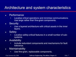
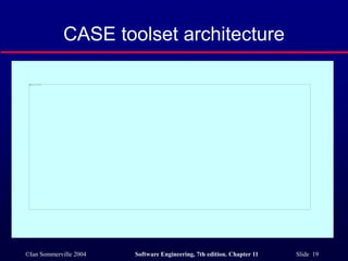
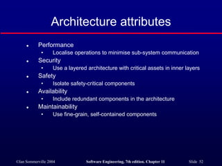
©Ian Sommerville 2004 Software Engineering, 7th edition. Chapter 11 Slide 1
Architectural Design
©Ian Sommerville 2004 Software Engineering, 7th edition. Chapter 11 Slide 2
Objectives
 To introduce architectural design and to
discuss its importance
 To explain the architectural design decisions
that have to be made
 To introduce three complementary
architectural styles covering organisation,
decomposition and control
 To discuss reference architectures are used
to communicate and compare architectures
©Ian Sommerville 2004 Software Engineering, 7th edition. Chapter 11 Slide 3
Topics covered
 Architectural design decisions
 System organisation
 Decomposition styles
 Control styles
 Reference architectures
©Ian Sommerville 2004 Software Engineering, 7th edition. Chapter 11 Slide 4
Software architecture
 The design process for identifying the sub-
systems making up a system and the
framework for sub-system control and
communication is architectural design.
 The output of this design process is a
description of the software architecture.
©Ian Sommerville 2004 Software Engineering, 7th edition. Chapter 11 Slide 5
Architectural design
 An early stage of the system design process.
 Represents the link between specification
and design processes.
 Often carried out in parallel with some
specification activities.
 It involves identifying major system
components and their communications.
©Ian Sommerville 2004 Software Engineering, 7th edition. Chapter 11 Slide 6
Advantages of explicit architecture
 Stakeholder communication
• Architecture may be used as a focus of
discussion by system stakeholders.
 System analysis
• Means that analysis of whether the system can
meet its non-functional requirements is
possible.
 Large-scale reuse
• The architecture may be reusable across a
range of systems.
©Ian Sommerville 2004 Software Engineering, 7th edition. Chapter 11 Slide 7
Architecture and system characteristics
 Performance
• Localise critical operations and minimise communications.
Use large rather than fine-grain components.
 Security
• Use a layered architecture with critical assets in the inner
layers.
 Safety
• Localise safety-critical features in a small number of sub-
systems.
 Availability
• Include redundant components and mechanisms for fault
tolerance.
 Maintainability
• Use fine-grain, replaceable components.
©Ian Sommerville 2004 Software Engineering, 7th edition. Chapter 11 Slide 8
Architectural conflicts
 Using large-grain components improves
performance but reduces maintainability.
 Introducing redundant data improves
availability but makes security more difficult.
 Localising safety-related features usually
means more communication so degraded
performance.
©Ian Sommerville 2004 Software Engineering, 7th edition. Chapter 11 Slide 9
System structuring
 Concerned with decomposing the system
into interacting sub-systems.
 The architectural design is normally
expressed as a block diagram presenting an
overview of the system structure.
 More specific models showing how sub-
systems share data, are distributed and
interface with each other may also be
developed.
©Ian Sommerville 2004 Software Engineering, 7th edition. Chapter 11 Slide 10
Packing robot control system
©Ian Sommerville 2004 Software Engineering, 7th edition. Chapter 11 Slide 11
Box and line diagrams
 Very abstract - they do not show the nature
of component relationships nor the externally
visible properties of the sub-systems.
 However, useful for communication with
stakeholders and for project planning.
©Ian Sommerville 2004 Software Engineering, 7th edition. Chapter 11 Slide 12
Architectural design decisions
 Architectural design is a creative process so
the process differs depending on the type of
system being developed.
 However, a number of common decisions
span all design processes.
©Ian Sommerville 2004 Software Engineering, 7th edition. Chapter 11 Slide 13
Architectural design decisions
 Is there a generic application architecture that can
be used?
 How will the system be distributed?
 What architectural styles are appropriate?
 What approach will be used to structure the system?
 How will the system be decomposed into modules?
 What control strategy should be used?
 How will the architectural design be evaluated?
 How should the architecture be documented?
©Ian Sommerville 2004 Software Engineering, 7th edition. Chapter 11 Slide 14
Architecture reuse
 Systems in the same domain often have
similar architectures that reflect domain
concepts.
 Application product lines are built around a
core architecture with variants that satisfy
particular customer requirements.
 Application architectures are covered in
Chapter 13 and product lines in Chapter 18.
©Ian Sommerville 2004 Software Engineering, 7th edition. Chapter 11 Slide 15
Architectural styles
 The architectural model of a system may
conform to a generic architectural model or
style.
 An awareness of these styles can simplify
the problem of defining system architectures.
 However, most large systems are
heterogeneous and do not follow a single
architectural style.
©Ian Sommerville 2004 Software Engineering, 7th edition. Chapter 11 Slide 16
Architectural models
 Used to document an architectural design.
 Static structural model that shows the major system
components.
 Dynamic process model that shows the process
structure of the system.
 Interface model that defines sub-system interfaces.
 Relationships model such as a data-flow model that
shows sub-system relationships.
 Distribution model that shows how sub-systems are
distributed across computers.
©Ian Sommerville 2004 Software Engineering, 7th edition. Chapter 11 Slide 17
System organisation
 Reflects the basic strategy that is used to
structure a system.
 Three organisational styles are widely used:
• A shared data repository style;
• A shared services and servers style;
• An abstract machine or layered style.
©Ian Sommerville 2004 Software Engineering, 7th edition. Chapter 11 Slide 18
The repository model
 Sub-systems must exchange data. This may
be done in two ways:
• Shared data is held in a central database or
repository and may be accessed by all sub-
systems;
• Each sub-system maintains its own database
and passes data explicitly to other sub-systems.
 When large amounts of data are to be
shared, the repository model of sharing is
most commonly used.
©Ian Sommerville 2004 Software Engineering, 7th edition. Chapter 11 Slide 19
CASE toolset architecture
©Ian Sommerville 2004 Software Engineering, 7th edition. Chapter 11 Slide 20
Repository model characteristics
 Advantages
• Efficient way to share large amounts of data;
• Sub-systems need not be concerned with how data is
produced Centralised management e.g. backup, security,
etc.
• Sharing model is published as the repository schema.
 Disadvantages
• Sub-systems must agree on a repository data model.
Inevitably a compromise;
• Data evolution is difficult and expensive;
• No scope for specific management policies;
• Difficult to distribute efficiently.
©Ian Sommerville 2004 Software Engineering, 7th edition. Chapter 11 Slide 21
Client-server model
 Distributed system model which shows how
data and processing is distributed across a
range of components.
 Set of stand-alone servers which provide
specific services such as printing, data
management, etc.
 Set of clients which call on these services.
 Network which allows clients to access
servers.
©Ian Sommerville 2004 Software Engineering, 7th edition. Chapter 11 Slide 22
Film and picture library
©Ian Sommerville 2004 Software Engineering, 7th edition. Chapter 11 Slide 23
Client-server characteristics
 Advantages
• Distribution of data is straightforward;
• Makes effective use of networked systems. May require
cheaper hardware;
• Easy to add new servers or upgrade existing servers.
 Disadvantages
• No shared data model so sub-systems use different data
organisation. Data interchange may be inefficient;
• Redundant management in each server;
• No central register of names and services - it may be hard
to find out what servers and services are available.
©Ian Sommerville 2004 Software Engineering, 7th edition. Chapter 11 Slide 24
Abstract machine (layered) model
 Used to model the interfacing of sub-systems.
 Organises the system into a set of layers (or abstract
machines) each of which provide a set of services.
 Supports the incremental development of sub-
systems in different layers. When a layer interface
changes, only the adjacent layer is affected.
 However, often artificial to structure systems in this
way.
©Ian Sommerville 2004 Software Engineering, 7th edition. Chapter 11 Slide 25
Version management system
©Ian Sommerville 2004 Software Engineering, 7th edition. Chapter 11 Slide 26
Modular decomposition styles
 Styles of decomposing sub-systems into
modules.
 No rigid distinction between system
organisation and modular decomposition.
©Ian Sommerville 2004 Software Engineering, 7th edition. Chapter 11 Slide 27
Sub-systems and modules
 A sub-system is a system in its own right
whose operation is independent of the
services provided by other sub-systems.
 A module is a system component that
provides services to other components but
would not normally be considered as a
separate system.
©Ian Sommerville 2004 Software Engineering, 7th edition. Chapter 11 Slide 28
Modular decomposition
 Another structural level where sub-systems are
decomposed into modules.
 Two modular decomposition models covered
• An object model where the system is decomposed into
interacting object;
• A pipeline or data-flow model where the system is
decomposed into functional modules which transform
inputs to outputs.
 If possible, decisions about concurrency should be
delayed until modules are implemented.
©Ian Sommerville 2004 Software Engineering, 7th edition. Chapter 11 Slide 29
Object models
 Structure the system into a set of loosely
coupled objects with well-defined interfaces.
 Object-oriented decomposition is concerned
with identifying object classes, their attributes
and operations.
 When implemented, objects are created from
these classes and some control model used
to coordinate object operations.
©Ian Sommerville 2004 Software Engineering, 7th edition. Chapter 11 Slide 30
Invoice processing system
©Ian Sommerville 2004 Software Engineering, 7th edition. Chapter 11 Slide 31
Object model advantages
 Objects are loosely coupled so their
implementation can be modified without
affecting other objects.
 The objects may reflect real-world entities.
 OO implementation languages are widely
used.
 However, object interface changes may
cause problems and complex entities may
be hard to represent as objects.
©Ian Sommerville 2004 Software Engineering, 7th edition. Chapter 11 Slide 32
Function-oriented pipelining
 Functional transformations process their
inputs to produce outputs.
 May be referred to as a pipe and filter model
(as in UNIX shell).
 Variants of this approach are very common.
When transformations are sequential, this is
a batch sequential model which is
extensively used in data processing systems.
 Not really suitable for interactive systems.
©Ian Sommerville 2004 Software Engineering, 7th edition. Chapter 11 Slide 33
Invoice processing system
©Ian Sommerville 2004 Software Engineering, 7th edition. Chapter 11 Slide 34
Pipeline model advantages
 Supports transformation reuse.
 Intuitive organisation for stakeholder
communication.
 Easy to add new transformations.
 Relatively simple to implement as either a
concurrent or sequential system.
 However, requires a common format for data
transfer along the pipeline and difficult to
support event-based interaction.
©Ian Sommerville 2004 Software Engineering, 7th edition. Chapter 11 Slide 35
Control styles
 Are concerned with the control flow between
sub-systems. Distinct from the system
decomposition model.
 Centralised control
• One sub-system has overall responsibility for
control and starts and stops other sub-systems.
 Event-based control
• Each sub-system can respond to externally
generated events from other sub-systems or the
system’s environment.
©Ian Sommerville 2004 Software Engineering, 7th edition. Chapter 11 Slide 36
Centralised control
 A control sub-system takes responsibility for
managing the execution of other sub-systems.
 Call-return model
• Top-down subroutine model where control starts at the top
of a subroutine hierarchy and moves downwards.
Applicable to sequential systems.
 Manager model
• Applicable to concurrent systems. One system
component controls the stopping, starting and
coordination of other system processes. Can be
implemented in sequential systems as a case statement.
©Ian Sommerville 2004 Software Engineering, 7th edition. Chapter 11 Slide 37
Call-return model
©Ian Sommerville 2004 Software Engineering, 7th edition. Chapter 11 Slide 38
Real-time system control
©Ian Sommerville 2004 Software Engineering, 7th edition. Chapter 11 Slide 39
Event-driven systems
 Driven by externally generated events where the
timing of the event is outwith the control of the sub-
systems which process the event.
 Two principal event-driven models
• Broadcast models. An event is broadcast to all sub-
systems. Any sub-system which can handle the event
may do so;
• Interrupt-driven models. Used in real-time systems where
interrupts are detected by an interrupt handler and passed
to some other component for processing.
 Other event driven models include spreadsheets
and production systems.
©Ian Sommerville 2004 Software Engineering, 7th edition. Chapter 11 Slide 40
Broadcast model
 Effective in integrating sub-systems on different
computers in a network.
 Sub-systems register an interest in specific events.
When these occur, control is transferred to the sub-
system which can handle the event.
 Control policy is not embedded in the event and
message handler. Sub-systems decide on events of
interest to them.
 However, sub-systems don’t know if or when an
event will be handled.
©Ian Sommerville 2004 Software Engineering, 7th edition. Chapter 11 Slide 41
Selective broadcasting
©Ian Sommerville 2004 Software Engineering, 7th edition. Chapter 11 Slide 42
Interrupt-driven systems
 Used in real-time systems where fast
response to an event is essential.
 There are known interrupt types with a
handler defined for each type.
 Each type is associated with a memory
location and a hardware switch causes
transfer to its handler.
 Allows fast response but complex to program
and difficult to validate.
©Ian Sommerville 2004 Software Engineering, 7th edition. Chapter 11 Slide 43
Interrupt-driven control
©Ian Sommerville 2004 Software Engineering, 7th edition. Chapter 11 Slide 44
Reference architectures
 Architectural models may be specific to some
application domain.
 Two types of domain-specific model
• Generic models which are abstractions from a number of
real systems and which encapsulate the principal
characteristics of these systems. Covered in Chapter 13.
• Reference models which are more abstract, idealised
model. Provide a means of information about that class of
system and of comparing different architectures.
 Generic models are usually bottom-up models;
Reference models are top-down models.
©Ian Sommerville 2004 Software Engineering, 7th edition. Chapter 11 Slide 45
Reference architectures
 Reference models are derived from a study
of the application domain rather than from
existing systems.
 May be used as a basis for system
implementation or to compare different
systems. It acts as a standard against which
systems can be evaluated.
 OSI model is a layered model for
communication systems.
©Ian Sommerville 2004 Software Engineering, 7th edition. Chapter 11 Slide 46
OSI reference model
©Ian Sommerville 2004 Software Engineering, 7th edition. Chapter 11 Slide 47
Case reference model
 Data repository services
• Storage and management of data items.
 Data integration services
• Managing groups of entities.
 Task management services
• Definition and enaction of process models.
 Messaging services
• Tool-tool and tool-environment communication.
 User interface services
• User interface development.
©Ian Sommerville 2004 Software Engineering, 7th edition. Chapter 11 Slide 48
The ECMA reference model
©Ian Sommerville 2004 Software Engineering, 7th edition. Chapter 11 Slide 49
Key points
 The software architecture is the fundamental
framework for structuring the system.
 Architectural design decisions include decisions on
the application architecture, the distribution and the
architectural styles to be used.
 Different architectural models such as a structural
model, a control model and a decomposition model
may be developed.
 System organisational models include repository
models, client-server models and abstract machine
models.
©Ian Sommerville 2004 Software Engineering, 7th edition. Chapter 11 Slide 50
Key points
 Modular decomposition models include
object models and pipelining models.
 Control models include centralised control
and event-driven models.
 Reference architectures may be used to
communicate domain-specific architectures
and to assess and compare architectural
designs.
©Ian Sommerville 2004 Software Engineering, 7th edition. Chapter 11 Slide 51
Architectural models
 Different architectural models may be
produced during the design process
 Each model presents different perspectives
on the architecture
©Ian Sommerville 2004 Software Engineering, 7th edition. Chapter 11 Slide 52
Architecture attributes
 Performance
• Localise operations to minimise sub-system communication
 Security
• Use a layered architecture with critical assets in inner layers
 Safety
• Isolate safety-critical components
 Availability
• Include redundant components in the architecture
 Maintainability
• Use fine-grain, self-contained components

Architectural Design Software Engineering 7th Edition

  • 1.
    ©Ian Sommerville 2004Software Engineering, 7th edition. Chapter 11 Slide 1 Architectural Design
  • 2.
    ©Ian Sommerville 2004Software Engineering, 7th edition. Chapter 11 Slide 2 Objectives  To introduce architectural design and to discuss its importance  To explain the architectural design decisions that have to be made  To introduce three complementary architectural styles covering organisation, decomposition and control  To discuss reference architectures are used to communicate and compare architectures
  • 3.
    ©Ian Sommerville 2004Software Engineering, 7th edition. Chapter 11 Slide 3 Topics covered  Architectural design decisions  System organisation  Decomposition styles  Control styles  Reference architectures
  • 4.
    ©Ian Sommerville 2004Software Engineering, 7th edition. Chapter 11 Slide 4 Software architecture  The design process for identifying the sub- systems making up a system and the framework for sub-system control and communication is architectural design.  The output of this design process is a description of the software architecture.
  • 5.
    ©Ian Sommerville 2004Software Engineering, 7th edition. Chapter 11 Slide 5 Architectural design  An early stage of the system design process.  Represents the link between specification and design processes.  Often carried out in parallel with some specification activities.  It involves identifying major system components and their communications.
  • 6.
    ©Ian Sommerville 2004Software Engineering, 7th edition. Chapter 11 Slide 6 Advantages of explicit architecture  Stakeholder communication • Architecture may be used as a focus of discussion by system stakeholders.  System analysis • Means that analysis of whether the system can meet its non-functional requirements is possible.  Large-scale reuse • The architecture may be reusable across a range of systems.
  • 7.
    ©Ian Sommerville 2004Software Engineering, 7th edition. Chapter 11 Slide 7 Architecture and system characteristics  Performance • Localise critical operations and minimise communications. Use large rather than fine-grain components.  Security • Use a layered architecture with critical assets in the inner layers.  Safety • Localise safety-critical features in a small number of sub- systems.  Availability • Include redundant components and mechanisms for fault tolerance.  Maintainability • Use fine-grain, replaceable components.
  • 8.
    ©Ian Sommerville 2004Software Engineering, 7th edition. Chapter 11 Slide 8 Architectural conflicts  Using large-grain components improves performance but reduces maintainability.  Introducing redundant data improves availability but makes security more difficult.  Localising safety-related features usually means more communication so degraded performance.
  • 9.
    ©Ian Sommerville 2004Software Engineering, 7th edition. Chapter 11 Slide 9 System structuring  Concerned with decomposing the system into interacting sub-systems.  The architectural design is normally expressed as a block diagram presenting an overview of the system structure.  More specific models showing how sub- systems share data, are distributed and interface with each other may also be developed.
  • 10.
    ©Ian Sommerville 2004Software Engineering, 7th edition. Chapter 11 Slide 10 Packing robot control system
  • 11.
    ©Ian Sommerville 2004Software Engineering, 7th edition. Chapter 11 Slide 11 Box and line diagrams  Very abstract - they do not show the nature of component relationships nor the externally visible properties of the sub-systems.  However, useful for communication with stakeholders and for project planning.
  • 12.
    ©Ian Sommerville 2004Software Engineering, 7th edition. Chapter 11 Slide 12 Architectural design decisions  Architectural design is a creative process so the process differs depending on the type of system being developed.  However, a number of common decisions span all design processes.
  • 13.
    ©Ian Sommerville 2004Software Engineering, 7th edition. Chapter 11 Slide 13 Architectural design decisions  Is there a generic application architecture that can be used?  How will the system be distributed?  What architectural styles are appropriate?  What approach will be used to structure the system?  How will the system be decomposed into modules?  What control strategy should be used?  How will the architectural design be evaluated?  How should the architecture be documented?
  • 14.
    ©Ian Sommerville 2004Software Engineering, 7th edition. Chapter 11 Slide 14 Architecture reuse  Systems in the same domain often have similar architectures that reflect domain concepts.  Application product lines are built around a core architecture with variants that satisfy particular customer requirements.  Application architectures are covered in Chapter 13 and product lines in Chapter 18.
  • 15.
    ©Ian Sommerville 2004Software Engineering, 7th edition. Chapter 11 Slide 15 Architectural styles  The architectural model of a system may conform to a generic architectural model or style.  An awareness of these styles can simplify the problem of defining system architectures.  However, most large systems are heterogeneous and do not follow a single architectural style.
  • 16.
    ©Ian Sommerville 2004Software Engineering, 7th edition. Chapter 11 Slide 16 Architectural models  Used to document an architectural design.  Static structural model that shows the major system components.  Dynamic process model that shows the process structure of the system.  Interface model that defines sub-system interfaces.  Relationships model such as a data-flow model that shows sub-system relationships.  Distribution model that shows how sub-systems are distributed across computers.
  • 17.
    ©Ian Sommerville 2004Software Engineering, 7th edition. Chapter 11 Slide 17 System organisation  Reflects the basic strategy that is used to structure a system.  Three organisational styles are widely used: • A shared data repository style; • A shared services and servers style; • An abstract machine or layered style.
  • 18.
    ©Ian Sommerville 2004Software Engineering, 7th edition. Chapter 11 Slide 18 The repository model  Sub-systems must exchange data. This may be done in two ways: • Shared data is held in a central database or repository and may be accessed by all sub- systems; • Each sub-system maintains its own database and passes data explicitly to other sub-systems.  When large amounts of data are to be shared, the repository model of sharing is most commonly used.
  • 19.
    ©Ian Sommerville 2004Software Engineering, 7th edition. Chapter 11 Slide 19 CASE toolset architecture
  • 20.
    ©Ian Sommerville 2004Software Engineering, 7th edition. Chapter 11 Slide 20 Repository model characteristics  Advantages • Efficient way to share large amounts of data; • Sub-systems need not be concerned with how data is produced Centralised management e.g. backup, security, etc. • Sharing model is published as the repository schema.  Disadvantages • Sub-systems must agree on a repository data model. Inevitably a compromise; • Data evolution is difficult and expensive; • No scope for specific management policies; • Difficult to distribute efficiently.
  • 21.
    ©Ian Sommerville 2004Software Engineering, 7th edition. Chapter 11 Slide 21 Client-server model  Distributed system model which shows how data and processing is distributed across a range of components.  Set of stand-alone servers which provide specific services such as printing, data management, etc.  Set of clients which call on these services.  Network which allows clients to access servers.
  • 22.
    ©Ian Sommerville 2004Software Engineering, 7th edition. Chapter 11 Slide 22 Film and picture library
  • 23.
    ©Ian Sommerville 2004Software Engineering, 7th edition. Chapter 11 Slide 23 Client-server characteristics  Advantages • Distribution of data is straightforward; • Makes effective use of networked systems. May require cheaper hardware; • Easy to add new servers or upgrade existing servers.  Disadvantages • No shared data model so sub-systems use different data organisation. Data interchange may be inefficient; • Redundant management in each server; • No central register of names and services - it may be hard to find out what servers and services are available.
  • 24.
    ©Ian Sommerville 2004Software Engineering, 7th edition. Chapter 11 Slide 24 Abstract machine (layered) model  Used to model the interfacing of sub-systems.  Organises the system into a set of layers (or abstract machines) each of which provide a set of services.  Supports the incremental development of sub- systems in different layers. When a layer interface changes, only the adjacent layer is affected.  However, often artificial to structure systems in this way.
  • 25.
    ©Ian Sommerville 2004Software Engineering, 7th edition. Chapter 11 Slide 25 Version management system
  • 26.
    ©Ian Sommerville 2004Software Engineering, 7th edition. Chapter 11 Slide 26 Modular decomposition styles  Styles of decomposing sub-systems into modules.  No rigid distinction between system organisation and modular decomposition.
  • 27.
    ©Ian Sommerville 2004Software Engineering, 7th edition. Chapter 11 Slide 27 Sub-systems and modules  A sub-system is a system in its own right whose operation is independent of the services provided by other sub-systems.  A module is a system component that provides services to other components but would not normally be considered as a separate system.
  • 28.
    ©Ian Sommerville 2004Software Engineering, 7th edition. Chapter 11 Slide 28 Modular decomposition  Another structural level where sub-systems are decomposed into modules.  Two modular decomposition models covered • An object model where the system is decomposed into interacting object; • A pipeline or data-flow model where the system is decomposed into functional modules which transform inputs to outputs.  If possible, decisions about concurrency should be delayed until modules are implemented.
  • 29.
    ©Ian Sommerville 2004Software Engineering, 7th edition. Chapter 11 Slide 29 Object models  Structure the system into a set of loosely coupled objects with well-defined interfaces.  Object-oriented decomposition is concerned with identifying object classes, their attributes and operations.  When implemented, objects are created from these classes and some control model used to coordinate object operations.
  • 30.
    ©Ian Sommerville 2004Software Engineering, 7th edition. Chapter 11 Slide 30 Invoice processing system
  • 31.
    ©Ian Sommerville 2004Software Engineering, 7th edition. Chapter 11 Slide 31 Object model advantages  Objects are loosely coupled so their implementation can be modified without affecting other objects.  The objects may reflect real-world entities.  OO implementation languages are widely used.  However, object interface changes may cause problems and complex entities may be hard to represent as objects.
  • 32.
    ©Ian Sommerville 2004Software Engineering, 7th edition. Chapter 11 Slide 32 Function-oriented pipelining  Functional transformations process their inputs to produce outputs.  May be referred to as a pipe and filter model (as in UNIX shell).  Variants of this approach are very common. When transformations are sequential, this is a batch sequential model which is extensively used in data processing systems.  Not really suitable for interactive systems.
  • 33.
    ©Ian Sommerville 2004Software Engineering, 7th edition. Chapter 11 Slide 33 Invoice processing system
  • 34.
    ©Ian Sommerville 2004Software Engineering, 7th edition. Chapter 11 Slide 34 Pipeline model advantages  Supports transformation reuse.  Intuitive organisation for stakeholder communication.  Easy to add new transformations.  Relatively simple to implement as either a concurrent or sequential system.  However, requires a common format for data transfer along the pipeline and difficult to support event-based interaction.
  • 35.
    ©Ian Sommerville 2004Software Engineering, 7th edition. Chapter 11 Slide 35 Control styles  Are concerned with the control flow between sub-systems. Distinct from the system decomposition model.  Centralised control • One sub-system has overall responsibility for control and starts and stops other sub-systems.  Event-based control • Each sub-system can respond to externally generated events from other sub-systems or the system’s environment.
  • 36.
    ©Ian Sommerville 2004Software Engineering, 7th edition. Chapter 11 Slide 36 Centralised control  A control sub-system takes responsibility for managing the execution of other sub-systems.  Call-return model • Top-down subroutine model where control starts at the top of a subroutine hierarchy and moves downwards. Applicable to sequential systems.  Manager model • Applicable to concurrent systems. One system component controls the stopping, starting and coordination of other system processes. Can be implemented in sequential systems as a case statement.
  • 37.
    ©Ian Sommerville 2004Software Engineering, 7th edition. Chapter 11 Slide 37 Call-return model
  • 38.
    ©Ian Sommerville 2004Software Engineering, 7th edition. Chapter 11 Slide 38 Real-time system control
  • 39.
    ©Ian Sommerville 2004Software Engineering, 7th edition. Chapter 11 Slide 39 Event-driven systems  Driven by externally generated events where the timing of the event is outwith the control of the sub- systems which process the event.  Two principal event-driven models • Broadcast models. An event is broadcast to all sub- systems. Any sub-system which can handle the event may do so; • Interrupt-driven models. Used in real-time systems where interrupts are detected by an interrupt handler and passed to some other component for processing.  Other event driven models include spreadsheets and production systems.
  • 40.
    ©Ian Sommerville 2004Software Engineering, 7th edition. Chapter 11 Slide 40 Broadcast model  Effective in integrating sub-systems on different computers in a network.  Sub-systems register an interest in specific events. When these occur, control is transferred to the sub- system which can handle the event.  Control policy is not embedded in the event and message handler. Sub-systems decide on events of interest to them.  However, sub-systems don’t know if or when an event will be handled.
  • 41.
    ©Ian Sommerville 2004Software Engineering, 7th edition. Chapter 11 Slide 41 Selective broadcasting
  • 42.
    ©Ian Sommerville 2004Software Engineering, 7th edition. Chapter 11 Slide 42 Interrupt-driven systems  Used in real-time systems where fast response to an event is essential.  There are known interrupt types with a handler defined for each type.  Each type is associated with a memory location and a hardware switch causes transfer to its handler.  Allows fast response but complex to program and difficult to validate.
  • 43.
    ©Ian Sommerville 2004Software Engineering, 7th edition. Chapter 11 Slide 43 Interrupt-driven control
  • 44.
    ©Ian Sommerville 2004Software Engineering, 7th edition. Chapter 11 Slide 44 Reference architectures  Architectural models may be specific to some application domain.  Two types of domain-specific model • Generic models which are abstractions from a number of real systems and which encapsulate the principal characteristics of these systems. Covered in Chapter 13. • Reference models which are more abstract, idealised model. Provide a means of information about that class of system and of comparing different architectures.  Generic models are usually bottom-up models; Reference models are top-down models.
  • 45.
    ©Ian Sommerville 2004Software Engineering, 7th edition. Chapter 11 Slide 45 Reference architectures  Reference models are derived from a study of the application domain rather than from existing systems.  May be used as a basis for system implementation or to compare different systems. It acts as a standard against which systems can be evaluated.  OSI model is a layered model for communication systems.
  • 46.
    ©Ian Sommerville 2004Software Engineering, 7th edition. Chapter 11 Slide 46 OSI reference model
  • 47.
    ©Ian Sommerville 2004Software Engineering, 7th edition. Chapter 11 Slide 47 Case reference model  Data repository services • Storage and management of data items.  Data integration services • Managing groups of entities.  Task management services • Definition and enaction of process models.  Messaging services • Tool-tool and tool-environment communication.  User interface services • User interface development.
  • 48.
    ©Ian Sommerville 2004Software Engineering, 7th edition. Chapter 11 Slide 48 The ECMA reference model
  • 49.
    ©Ian Sommerville 2004Software Engineering, 7th edition. Chapter 11 Slide 49 Key points  The software architecture is the fundamental framework for structuring the system.  Architectural design decisions include decisions on the application architecture, the distribution and the architectural styles to be used.  Different architectural models such as a structural model, a control model and a decomposition model may be developed.  System organisational models include repository models, client-server models and abstract machine models.
  • 50.
    ©Ian Sommerville 2004Software Engineering, 7th edition. Chapter 11 Slide 50 Key points  Modular decomposition models include object models and pipelining models.  Control models include centralised control and event-driven models.  Reference architectures may be used to communicate domain-specific architectures and to assess and compare architectural designs.
  • 51.
    ©Ian Sommerville 2004Software Engineering, 7th edition. Chapter 11 Slide 51 Architectural models  Different architectural models may be produced during the design process  Each model presents different perspectives on the architecture
  • 52.
    ©Ian Sommerville 2004Software Engineering, 7th edition. Chapter 11 Slide 52 Architecture attributes  Performance • Localise operations to minimise sub-system communication  Security • Use a layered architecture with critical assets in inner layers  Safety • Isolate safety-critical components  Availability • Include redundant components in the architecture  Maintainability • Use fine-grain, self-contained components