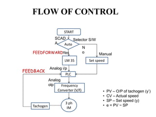
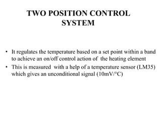
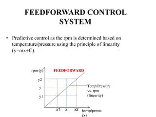
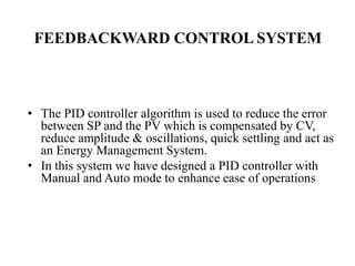
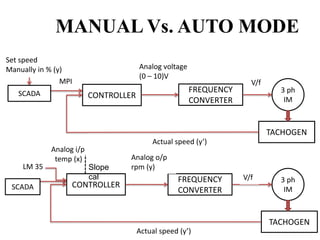
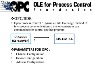
BY
JAYARAM .K.S(31708107043)
INTERNAL GUIDE-Mr. VIJAYA RAMRAJ
RANGAM ,M.E., (Assistant PROFESSOR)
Department Of ICE
DYNAMIC CONTROL SYSTEM
WITH RESPECT TO A LINEAR
RELATIONSHIP
INTRODUCTION
• To analyze the operation of a control system on a real
time basis which can be applied in an industrial field.
• System Control is achieved by using a Two
postion,feed forward and a feedback loop with Alarm
circuitry for interlocks operation.
• To develop a security based control system using
SCADA for controlling and monitoring system
parameters.
• Temp Sensor (LM 35 -10mV/°C)
• Pressure Sensor (M5100)
• PAC (Siemens S7-300)
• VFD(MM440)
• 3 phase IM
• Tachogenerator
• OPC /DDE (KEPSERVER EX V4.0)
• SCADA (Wonderware software)
COMPONENTS
FLOW OF CONTROL
START
Auto
LM 35
SCAD
A
PLC
Frequency
Converter (V/f)
3 ph
IM
Yes
Set speed
N
o
Analog i/p
Analog
olp
Selector S/W
Manual
Tachogen
FEEDBACK
FEEDFORWARD
• PV – O/P of tachogen (y’)
• CV – Actual speed
• SP – Set speed (y)
• e = PV ~ SP
FIELD APPLICATION
RECYCLING
WASTE PAPER
TONNES OF
PAPER IS
ROLLED
DIMENSIONS
MAINTAINED –
ROLLING MILLS
IF ANY DIFFERENCE IN
DIMENSION ON EITHER END
BASED ON LINEARITY OF
DIMENSION vs RPM , SPEED IS SET
1. PAPER INDUSTRY
INLET VAPOURS
IN KOD
HEAT DUE TO
EXOTHERMIC
REACTION
INC IN TEMP SHOWS
INC IN VAPOUR
NEED MORE
COMPRESSION
INCREASE IN
SPEED OF IMPELLER
IMPELLER
COMPRESSES
VAPOUR
HEAT REDUCED
RESULTS
COMPRESSION
REDUCTION
2. CHEMICAL INDUSTRY
• It regulates the temperature based on a set point within a band
to achieve an on/off control action of the heating element
• This is measured with a help of a temperature sensor (LM35)
which gives an unconditional signal (10mV/°C)
TWO POSITION CONTROL
SYSTEM
• Predictive control as the rpm is determined based on
temperature/pressure using the principle of linearity
(y=mx+C).
FEEDFORWARD CONTROL
SYSTEM
rpm (y)
temp/press
(x)
x1 x2
y1
y2
x
y Temp/Pressure
vs. rpm
(linearity)
FEEDFORWARD
• Variable speed is achieved using VFD that
generates variable frequency supply with constant
voltage to frequency ratio.[Performance range :
0.12 – 250KW]
MICROMASTER 440
 MOTOR PLATE DETAILS
• Select Motor Type – Asyn.motor ( 3ph IM )
• Rated Motor Voltage – 415 V
• Rated Motor Current – 1.4 A
• Rated Motor Power – 0.37 KW
• Rated Motor cosØ – 0.8
• Rated Motor Efficiency – 70%
• Rated Motor Frequency – 50 Hz
• Rated Motor Speed – 1440 rpm
 CONTROL MODE
• Selection Of Command Source – BOP
COMMISSIONING THE DRIVE BASED
ON APPLICATION
• The PID controller algorithm is used to reduce the error
between SP and the PV which is compensated by CV,
reduce amplitude & oscillations, quick settling and act as
an Energy Management System.
• In this system we have designed a PID controller with
Manual and Auto mode to enhance ease of operations
FEEDBACKWARD CONTROL SYSTEM
MANUAL Vs. AUTO MODE
CONTROLLER
FREQUENCY
CONVERTER
TACHOGEN
Analog i/p
temp (x)
Slope
cal
Analog o/p
rpm (y)
3 ph
IM
V/f
Actual speed (y’)
SCADA
LM 35
CONTROLLER
FREQUENCY
CONVERTER
TACHOGEN
3 ph
IM
V/f
Actual speed (y’)
Set speed
Manually in % (y)
SCADA
Analog voltage
(0 – 10)V
MPI
ORGANIZATION BLOCKS (OB’S)
• 122 OB’s ,29 priorities
• There are 5 types :
1. Main Program Scan
(OB1, lowest priority )
2. Errors
3. Interrupts
4. Startup
5. Background cycle
(OB90, highest priority )
RACK SYSTEM :
 CR – Centralized Rack
 ER – Expansion Rack
 UR-Universal Rack
• Slot 1 : Power Supply
• Slot 2 : CPU modules
• Slot 3 : IM modules
• Slot (4-11) : SM modules
Function Call ( FC’s in OB1)
• Variable declaration table :
• IN , OUT & TEMP
DATA BLOCK (DB’S)
• Contains only variable declaration section
• Can be viewed in “declaration” or “data” view
• Makes use of memory interface
• There are two types
• Shared DB
• Instance DB
FAULT – ALARM SYSTEM
ALARM
HEALTHY
ACK
SIREN
LAMP
CIRCUIT DIAGRAM
HARDWARE SETUP
OPC/DDE :
• Open Process Control / Dynamic Data Exchange method of
interprocess communication so that one program can
communicate or control another program
PARAMETERS FOR OPC :
• Channel Configuration
• Device Configuration
• Address Configuration
OPC/DDE
(KEPSERVER)
MS-EXCEL
OPC – DA
SIEMENS S7 MPI
S7-300 CONTROLLER
OPC
DDE CLIENT DRIVE
OPC MS-EXCEL
OPC – DX
DDE CLIENT DRIVE
PROGRAMMING
S7300.doc
THANK YOU

BATCH15

  • 1.
    BY JAYARAM .K.S(31708107043) INTERNAL GUIDE-Mr.VIJAYA RAMRAJ RANGAM ,M.E., (Assistant PROFESSOR) Department Of ICE DYNAMIC CONTROL SYSTEM WITH RESPECT TO A LINEAR RELATIONSHIP
  • 2.
    INTRODUCTION • To analyzethe operation of a control system on a real time basis which can be applied in an industrial field. • System Control is achieved by using a Two postion,feed forward and a feedback loop with Alarm circuitry for interlocks operation. • To develop a security based control system using SCADA for controlling and monitoring system parameters.
  • 3.
    • Temp Sensor(LM 35 -10mV/°C) • Pressure Sensor (M5100) • PAC (Siemens S7-300) • VFD(MM440) • 3 phase IM • Tachogenerator • OPC /DDE (KEPSERVER EX V4.0) • SCADA (Wonderware software) COMPONENTS
  • 4.
    FLOW OF CONTROL START Auto LM35 SCAD A PLC Frequency Converter (V/f) 3 ph IM Yes Set speed N o Analog i/p Analog olp Selector S/W Manual Tachogen FEEDBACK FEEDFORWARD • PV – O/P of tachogen (y’) • CV – Actual speed • SP – Set speed (y) • e = PV ~ SP
  • 5.
    FIELD APPLICATION RECYCLING WASTE PAPER TONNESOF PAPER IS ROLLED DIMENSIONS MAINTAINED – ROLLING MILLS IF ANY DIFFERENCE IN DIMENSION ON EITHER END BASED ON LINEARITY OF DIMENSION vs RPM , SPEED IS SET 1. PAPER INDUSTRY INLET VAPOURS IN KOD HEAT DUE TO EXOTHERMIC REACTION INC IN TEMP SHOWS INC IN VAPOUR NEED MORE COMPRESSION INCREASE IN SPEED OF IMPELLER IMPELLER COMPRESSES VAPOUR HEAT REDUCED RESULTS COMPRESSION REDUCTION 2. CHEMICAL INDUSTRY
  • 6.
    • It regulatesthe temperature based on a set point within a band to achieve an on/off control action of the heating element • This is measured with a help of a temperature sensor (LM35) which gives an unconditional signal (10mV/°C) TWO POSITION CONTROL SYSTEM
  • 7.
    • Predictive controlas the rpm is determined based on temperature/pressure using the principle of linearity (y=mx+C). FEEDFORWARD CONTROL SYSTEM rpm (y) temp/press (x) x1 x2 y1 y2 x y Temp/Pressure vs. rpm (linearity) FEEDFORWARD
  • 8.
    • Variable speedis achieved using VFD that generates variable frequency supply with constant voltage to frequency ratio.[Performance range : 0.12 – 250KW] MICROMASTER 440
  • 9.
     MOTOR PLATEDETAILS • Select Motor Type – Asyn.motor ( 3ph IM ) • Rated Motor Voltage – 415 V • Rated Motor Current – 1.4 A • Rated Motor Power – 0.37 KW • Rated Motor cosØ – 0.8 • Rated Motor Efficiency – 70% • Rated Motor Frequency – 50 Hz • Rated Motor Speed – 1440 rpm  CONTROL MODE • Selection Of Command Source – BOP COMMISSIONING THE DRIVE BASED ON APPLICATION
  • 10.
    • The PIDcontroller algorithm is used to reduce the error between SP and the PV which is compensated by CV, reduce amplitude & oscillations, quick settling and act as an Energy Management System. • In this system we have designed a PID controller with Manual and Auto mode to enhance ease of operations FEEDBACKWARD CONTROL SYSTEM
  • 11.
    MANUAL Vs. AUTOMODE CONTROLLER FREQUENCY CONVERTER TACHOGEN Analog i/p temp (x) Slope cal Analog o/p rpm (y) 3 ph IM V/f Actual speed (y’) SCADA LM 35 CONTROLLER FREQUENCY CONVERTER TACHOGEN 3 ph IM V/f Actual speed (y’) Set speed Manually in % (y) SCADA Analog voltage (0 – 10)V MPI
  • 12.
    ORGANIZATION BLOCKS (OB’S) •122 OB’s ,29 priorities • There are 5 types : 1. Main Program Scan (OB1, lowest priority ) 2. Errors 3. Interrupts 4. Startup 5. Background cycle (OB90, highest priority ) RACK SYSTEM :  CR – Centralized Rack  ER – Expansion Rack  UR-Universal Rack • Slot 1 : Power Supply • Slot 2 : CPU modules • Slot 3 : IM modules • Slot (4-11) : SM modules
  • 13.
    Function Call (FC’s in OB1) • Variable declaration table : • IN , OUT & TEMP
  • 14.
    DATA BLOCK (DB’S) •Contains only variable declaration section • Can be viewed in “declaration” or “data” view • Makes use of memory interface • There are two types • Shared DB • Instance DB
  • 15.
    FAULT – ALARMSYSTEM ALARM HEALTHY ACK SIREN LAMP
  • 16.
  • 17.
  • 22.
    OPC/DDE : • OpenProcess Control / Dynamic Data Exchange method of interprocess communication so that one program can communicate or control another program PARAMETERS FOR OPC : • Channel Configuration • Device Configuration • Address Configuration OPC/DDE (KEPSERVER) MS-EXCEL
  • 23.
  • 24.
    SIEMENS S7 MPI S7-300CONTROLLER OPC DDE CLIENT DRIVE OPC MS-EXCEL OPC – DX
  • 25.
  • 26.
  • 27.