
More Related Content
What's hot
What's hot (18)
Similar to MK1_Addendum
Similar to MK1_Addendum (20)
MK1_Addendum
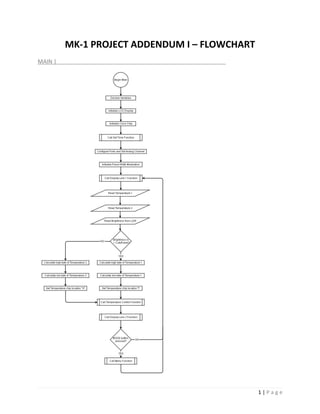
- 1. MK-1 PROJECT ADDENDUM I – FLOWCHART MAIN | 1 | P a g e
- 2. MENU | 2 | P a g e
- 3. SET TIME | 3 | P a g e
- 4. SET TEMPERATURE | 4 | P a g e
- 5. DISPLAY LINE 1 | 5 | P a g e
- 6. DISPLAY LINE 2, DISPLAY TIME | 6 | P a g e
- 7. TEMPERATURE CONTROL | 7 | P a g e
- 8. MK-1 PROJECT ADDENDUM II – CODE Prototype.h | #include <16f877A.h> #fuses HS, NOLVP, NOWDT, PUT #use delay ( clock = 20000000 ) #use rs232 (baud=9600, xmit=PIN_C6, rcv=PIN_C7) //Serial port monitor connection #define green_led PIN_A5 //green led connected to A5 (pin 8) #define yellow_led PIN_B4 //yellow led connected to B4 (pin 41) #define red_led PIN_B5 //red led connected to B5 (pin 42) #define push_button PIN_A4 //Push button connected to A4 (pin 7) extern char stat; extern char tod[3][3] = {"am", "pm"}; extern int1 i = 1; 8 | P a g e
- 9. FinalProject_MK2.c | /*************************************************** Brandon Hargrave DATE: February 11, 2014 Project Name: Final Project Discription: Geo-Thermal Heat Exchanger ***************************************************/ #include <prototype.h> #include <ds1631lite.c> #include <nju6355.c> #include <bcd_lcd.c> #include <lcd_functions.c> #define cutoff 80 #define MODE PIN_B7 #define BUTTON1 PIN_B5 #define BUTTON2 PIN_B6 #define SELECT_CLR PIN_B3 9 | P a g e
- 10. /*************************************************** display_line1() + display_line1() ***************************************************/ void time_display(int hour, min, char s) { printf(lcd_putc,"f %c%c%c:%c%c%s", s, display_first_bcd(hour, 1), display_second_bcd(hour), display_first_bcd(min, 0), display_second_bcd(min), tod[i]); } void display_line1(int hour, min, sec) { int last_min; rtc_get_time (hour, min, sec); //read time from chip if(min!=last_min) //display & update time on lcd { time_display(hour, min, ' '); //display time on lcd last_min = min; } 10 | P a g e
- 11. if(hour > 0x12) //roll over from 12 O'clock to 1 {hour = 0x1; rtc_set_datetime(0, 0, 0, 0, hour, min); i ^= 1;} //toggle between am and pm when hour passes 12 } void display_line2(char tcl, stat, int temp_displ, temp_disph) { printf(lcd_putc, "n%cTemp: %d.%dF (%c)", tcl ,temp_disph, temp_displ, stat); } //display temp, chip location, and heat pump status(heat or cool) on lcd /*************************************************** temp_control() ***************************************************/ void temp_control(long temp1, long thermostat) //control heat pump direction and duty cycle { long dtemp; if(Temp1 > thermostat) //inside warmer then thermostat setting {output_low(PIN_C0); //Heat >> Earth Cooling output_high(PIN_C1); stat = 'C';} else if(Temp1 < thermostat) //if inside cooler then thermostat setting {output_low(PIN_C1); //Heat >> Inside Heating 11 | P a g e
- 12. output_high(PIN_C0); stat = 'H';} dtemp = temp1 - thermostat; //find difference of temp 1 & 2 if (thermostat > temp1) //negative value expected dtemp = ~dtemp & 0b0111111111111111; //1's compliment and set sign bit 0 if(dtemp > 200) CCP_1 = 20; //80% duty cycle (driving gate of pnp) else if(dtemp > 50) //inside temp > or < than earth temp atleast 2o CCP_1 = 85; //15% duty cycle else //temp within + or - 0.5o {CCP_1 = 100; //Heat pump off stat = 'S';} } /*************************************************** set_time() ***************************************************/ void set_time() { int hour_dec = 12, min_dec = 0; 12 | P a g e
- 13. int hour, min; int incr = 0; //increment time int ts = 0; //timer set printf(lcd_putc, "c"); //clear screen before thermostat screen displayed while(!ts) { if(!(input(BUTTON2) || incr)) //increment min once if pressed {min_dec ++; incr = 1;} else if(!(input(BUTTON1) || incr)) //increment hour once if pressed {hour_dec ++; incr = 1;} else if(input(BUTTON1) && input(BUTTON2) && incr) //reset incr flag incr = 0; if(min_dec > 59) //reset min to 0 and roll over hour {min_dec = 0; hour_dec ++;} if(hour_dec > 12) //reset hour to 1 {hour_dec = 1; i ^= 1;} //toggle between am and pm when hour passes 12 13 | P a g e
- 14. min = get_bcd(min_dec); //convert min int into bcd hour = get_bcd(hour_dec); //convert hour int into bcd time_display(hour, min, '>'); //display time on lcd if(!input(SELECT_CLR)) //reset time if mode button is pressed {while(!input(SELECT_CLR)) delay_ms(500); ts = 1;} //run program when pressed } rtc_set_datetime(0, 0, 0, 0, hour, min); //set selected time } /*************************************************** set_temp() ***************************************************/ long set_temp(long thermostat) { int ts = 0; long temp; printf(lcd_putc, "c"); //clear screen before thermostat screen displayed 14 | P a g e
- 15. while(!ts) { if(!input(BUTTON1)) //press to increment thermostat setting {while(!input(BUTTON1)) delay_ms(100); thermostat += 100;} if(!input(BUTTON2)) //press to decrement thermostat setting {while(!input(BUTTON2)) delay_ms(100); thermostat -= 100;} temp = thermostat / 100; printf(lcd_putc, "n>Temp: %ldF", temp); //display temp while being set if(!input(SELECT_CLR)) //press select to set thermostat {while(!input(SELECT_CLR)) delay_ms(500); ts = 1;} } return thermostat; //return new thermostat setting to menu function } 15 | P a g e
- 16. /*************************************************** menu() ***************************************************/ long menu(long thermostat) { int screen = 1; int exit_flag = 0; //ensures return to main after menu selection made printf(lcd_putc, "c"); //clear screen for menu to display while(!exit_flag) { if(!input(MODE)) //mode increments screen cycles through menu options { while(!input(MODE)) delay_ms(100); screen++; //display next menu option } if(screen > 2) //cycle menu options {screen = 1; printf(lcd_putc, "c");} 16 | P a g e
- 17. printf(lcd_putc, "fMenu %d/2",screen); switch(screen) { case 1: printf(lcd_putc, "n>Set Time"); if(!input(SELECT_CLR)){ //press select button to display selected item while(!input(SELECT_CLR)) delay_ms(500); set_time(); //enter set time screen on lcd exit_flag = 1;} break; case 2: printf(lcd_putc, "n>Set Thermostat"); if(!input(SELECT_CLR)){ //press select button to display selected item while(!input(SELECT_CLR)) delay_ms(500); thermostat = set_temp(thermostat); //enter thermostat display on lcd exit_flag = 1;} break; } } return thermostat; } 17 | P a g e
- 18. /**************************************************************** Main *****************************************************************/ void main() { // main int hour, min, sec; long temp1, temp2, thermostat = 6800; unsigned int temp_displ, temp_disph; unsigned int brightness; char tcl; lcd_init(); //init lcd rtc_init(); //init clock chip set_time(); //function to set the time setup_adc_ports(RA0_RA1_RA3_ANALOG); setup_adc(ADC_CLOCK_INTERNAL); set_adc_channel(3); delay_us(10); 18 | P a g e
- 19. setup_timer_2(T2_DIV_BY_1,99,1); //enable timer2, PR2=99, prescaler = 1 setup_ccp1(CCP_PWM); //enable PWM mode while(1) { display_line1(hour, min, sec); //display line 1 of lcd temp1 = read_full_temp(address[0]); //read chip1 temp2 = read_full_temp(address[1]); //read chip2 brightness = read_adc(); //read ldr if(brightness < cutoff) //compare ldr to cutoff to determine which chip to read {temp_disph = (temp1 / 100); temp_displ = (temp1 % 100) / 10; tcl = 'I';} //temp chip location inside else {temp_disph = (temp2 / 100); temp_displ = (temp2 % 100) / 10; tcl = 'G';} //temp chip location ground temp_control(temp1, thermostat),; display_line2(tcl, stat, temp_displ, temp_disph); //display line 2 of lcd 19 | P a g e
- 20. if(!input(MODE)) //reset time if mode button is pressed {while(!input(MODE)) delay_ms(500); thermostat = menu(thermostat);} //return thermostats setting from menu } } // main 20 | P a g e
- 21. ds1631lite.c | #ifndef DAL_SCL #define DAL_SCL PIN_E1 #define DAL_SDA PIN_E2 #endif #define read_temp read_full_temp // for backwards compatability #use i2c(master, sda=DAL_SDA, scl=DAL_SCL) int address[3] = //array of chip addresses { 0x00 0x02 0x04 }; signed long read_full_temp(BYTE chip) { // Returns hundreths of degrees F (-67 to 257) signed int datah, datal; signed long data; i2c_start(); i2c_write(0x90 + chip); 21 | P a g e
- 22. i2c_write(0xaa); i2c_start(); i2c_write(0x91 + chip); datah=i2c_read(); datal=i2c_read(0); i2c_stop(); data=(signed long)datah*100; data=data+(((datal >> 4 )*(long)50)/16); data=data*9; data = (data / 5) + 3200; return(data); } 22 | P a g e
- 23. bcd_lcd.c | /*************************************************** get_bcd() ***************************************************/ //converts an integer into a two digit bcd number // ie: (12) 00001110 --> 0001|0010 byte get_bcd(int num) { int first, second; do { first=num/10; } while ((first<0) || (first>9)); do { second=num%10; } while ((second<0) || (second>9)); return (((first) << 4) | (second)); } 23 | P a g e
- 24. /*************************************************** display_first_bcd() + display_second_bcd() ***************************************************/ char display_first_bcd(byte n, int i) { char bcd; bcd = n/16+'0'; //isolates first digit, adds extra ascii bits if((bcd == '0') && (i)){ //if function called with hour and first digit = 0 bcd = 32;} //use ascii space instead return bcd; } char display_second_bcd(byte n) { return n%16+'0'; //isolates second digit, adds extra ascii bits } 24 | P a g e
- 25. lcd_functions.c | #define LCD_E PIN_C5 #define LCD_RS PIN_C4 /**************************************************************** int const LCD_INIT_STRING[5] *****************************************************************/ int const LCD_INIT_STRING[5] = //string of 1 byte commands for the lcd { 0x38, //Func set: 8-bit, 2 lines 0x08, //Don't shift display, hide cursor 1, //Clear memory 6, //Increment cursor 0xc, //Display on }; /**************************************************************** void lcd_send_byte() *****************************************************************/ void lcd_send_byte(int address, int n) { output_low(LCD_E); //enable lcd 25 | P a g e
- 26. delay_us(60); if(address) //RS bit determines if byte is a command or display data output_high(LCD_RS); //byte is data else output_low(LCD_RS); //byte is command delay_cycles(1); output_d(n); output_high(LCD_E); //making lcd_e high then low cycles the power delay_ms(1); //and clears the screen output_low(LCD_E); delay_ms(5); } /**************************************************************** void lcd_init(void) *****************************************************************/ void lcd_init(void) { int i; output_low(LCD_RS); output_low(LCD_E); 26 | P a g e
- 27. delay_ms(15); for(i=0;i<3;i++) { output_d(0x30); delay_ms(5); } for(i=0;i<sizeof(LCD_INIT_STRING); i++) { lcd_send_byte(0,LCD_INIT_STRING[i]); //cycles through array of lcd init commands } } //end lcd_init /**************************************************************** void lcd_putc(char c) *****************************************************************/ void lcd_putc(char c) { switch(c) { case'c': lcd_send_byte(0,1); //(RS bit, byte) delay_ms(2); 27 | P a g e
- 29. MK-1 PROJECT ADDENDUM III – TROUBLESHOOTING Function names are in italics: function(). PROBLEM 1 | PROBLEM ENCOUNTERED: The LCD display would display null characters and wrong characters rather than the time when the program was running the set_time() function. SOURCE: A mismatch of data types. The clock chip and LCD would not read the hour and min integers, the devices were setup to receive 2 digit BCD variables. The get_bcd() function was implemented in the stock code to convert a character returned from getc(), to BCD, in order to make it readable for the devices. ACTIONS TAKEN: Modified get_bcd() function to be called with the hour and min integers, then to return hour and min 2 digit BCD variables. FINAL SOLUTION: The get_bcd() function now splits integers into two BCD values. The first digit is isolated via dividing the integer by 10, the second via finding modulus 10. The first digit is bit shifted up by 4. Then the first and second digits are or’d together then returned from the function. The returned value is a 2 digit BCD variable. PROBLEM 2 | PROBLEM ENCOUNTERED: It was impossible to use i2c to communicate with multiple ds1631 chips with the stock include file. SOURCE: The stock ds1631.c include file declared a single chip address as a hardware define. All functions within that required a chip address were called with a single hex value containing command and address bits. ACTIONS TAKEN: The hardware define was removed, an array of chip addresses was defined in its place. All instances of i2c_write() in ds1631.c had address bits subtracted from their hex values to accommodate address bits from the address array. FINAL SOLUTION: Functions temp_init() and read_full_temp() are now called with addresses from the array, the carried value is declared as “chip” in the function. Any instance of i2c_write() is called with the sum of the command bits, and the new address bits from the array. Ex: i2c_write(0x91 + chip). 29 | P a g e
- 30. PROBLEM 3 | PROBLEM ENCOUNTERED: Ran out of ROM when writing the program. SOURCE: Temperature floating point variables used up a significant chunk of program memory. ACTIONS TAKEN: Long integers were declared in place of the floating point variables for use as temperature variables. A new ds1631_lite.c function was created without the temp_init() function. Said function was moved to a separate temperature chip initialization program: init_temp.c. The display_time() function was created to be called by set_time() and display_line1(), eliminating some redundant code. FINAL SOLUTION: Temp1 or Temp2 integers were split into a high display byte and a low display byte, then called by a printf() function and displayed on either side of a decimal point to look like a float. The temperature chips are now initialized by the temp_init.c program with lines temp_init(address[0]) and temp_init(address[1]). Function display_time() contains a printf() responsible for displaying the time on the first line of the LCD display. The printf() is now called with a character declared as ‘s’ in display_time(). The ‘s’ character determines if an arrow is present in front of the time when it is being set. When the function is called from set_time(), it is called with the ‘>’ character. If called from display_line1() then display_time() is called with an ascii space character instead. 30 | P a g e
- 31. MK-1 PROJECT ADDENDUM IV – PROTOTYPING SETUP MATERIALS | Software CCS C Compiler PICKit 2 V2.16 Hardware Toshiba Satellite laptop CanaKit UK1300 Programmer PIC16f877a Board RJ-11 Cable (Programmer Interface) Custom 9 pin Serial – 1/8” Stereo plug, cable (Serial Port Interface) USB Type 1 – USB Type 2 cable (PC Interface) MB-108 Circuit-Test Breadboard 34 pin Ribbon Cable 34 pin Breadboard Connector Breadboard 22 gauge wire: Red, Black, Orange, Yellow, White Stranded Male – Male jumper wires Power Supply The power supply is a 9V wall wart which powers an LM7805, 5 volt positive voltage regulator mounted on the 16F877a board. The regulator provides power directly to the microcontroller, and to the breadboard through 4 pins on the ribbon cable. See Bill of Materials in the Owner’s Manual for a complete list of circuit components. 31 | P a g e
- 32. PROGRAMMER SETUP | 32 | P a g e
- 33. BREADBOARD BUILD | NOTE: For the prototype a function generator was used in place of a crystal as the clock signal for the 6355ED clock chip. 33 | P a g e