Downloaded 222 times
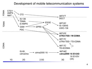
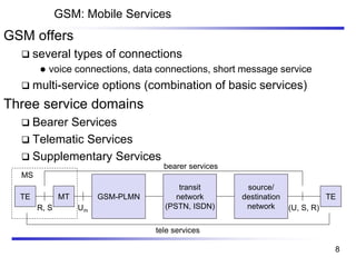
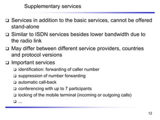
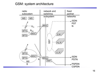
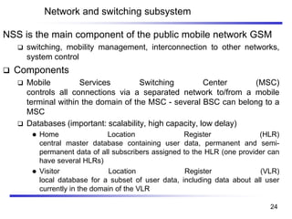
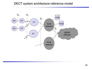
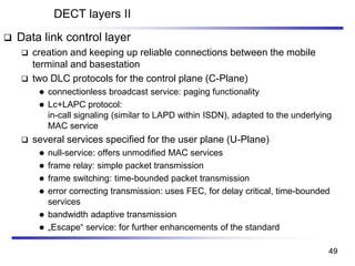
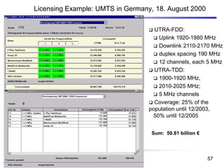
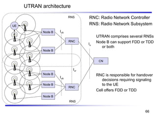
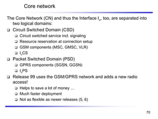
![Mobile phone subscribers worldwide
0
200
400
600
800
1000
1200
1996 1997 1998 1999 2000 2001 2002
year
Subscribers[million]
GSM total
TDMA total
CDMA total
PDC total
Analogue total
Total wireless
Prediction (1998)
3](https://image.slidesharecdn.com/cs86012-191218042117/85/CS8601-MOBILE-COMPUTING-3-320.jpg)
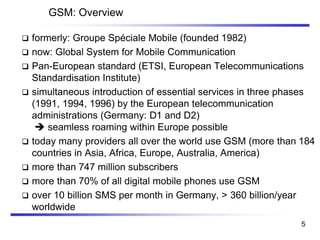
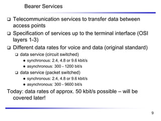
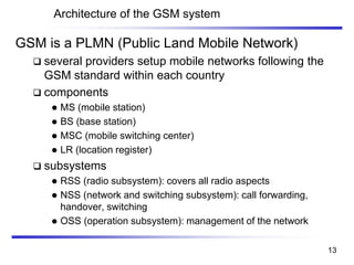
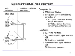
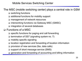
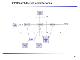
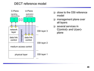
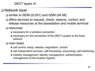
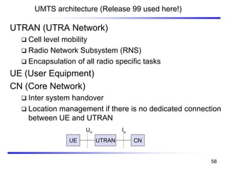
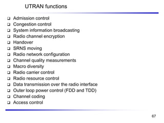
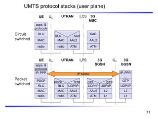
![Data services in GSM I
Data transmission standardized with only 9.6 kbit/s
❑ advanced coding allows 14,4 kbit/s
❑ not enough for Internet and multimedia applications
HSCSD (High-Speed Circuit Switched Data)
❑ mainly software update
❑ bundling of several time-slots to get higher
AIUR (Air Interface User Rate)
(e.g., 115.2 kbit/s using 8 slots, 14.4 each)
❑ advantage: ready to use, constant quality, simple
❑ disadvantage: channels blocked for voice transmission
AIUR [kbit/s] TCH/F4.8 TCH/F9.6 TCH/F14.4
4.8 1
9.6 2 1
14.4 3 1
19.2 4 2
28.8 3 2
38.4 4
43.2 3
57.6 4
39](https://image.slidesharecdn.com/cs86012-191218042117/85/CS8601-MOBILE-COMPUTING-39-320.jpg)
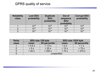


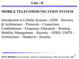
The document presents an overview of mobile telecommunications, specifically focusing on GSM (Global System for Mobile Communication). It discusses the architecture, services, and performance characteristics of GSM, as well as security features, bearer and tele services, and the role of mobile switching centers. Additionally, it highlights the disadvantages and complexities of GSM systems, along with the evolution of mobile communication standards from 1G to 3G and beyond.