Download to read offline
![Nirajkumar R.Sindhi. et.al. Int. Journal of Engineering Research and Applications www.ijera.com
ISSN: 2248-9622, Vol. 6, Issue 5, (Part - 1) May 2016, pp.43-47
www.ijera.com 43|P a g e
Study of Steel Moment Resisting Frame with Reduced Beam
Section
Nirajkumar R.Sindhi1
, Jasmin A.Gadhiya2
, Hitesh K.Dhameliya3
1, 2, 3
(Department of Civil Engineering, CGPIT, UTU University, Tarsadi, Surat)
ABSTRACT
A research became necessary after the collapse of steel structure during the 1994 Northridge and 1995 Kobe
earthquakes. Reduced beam section emerged as one of the best solution. Guidelines about the cut, that is to be
introduced in the flange of the beam section, are obtained from FEMA 350. Here, a G+15 storey steel building is
modeled using RBS as a component in one building and regular beam section as a component of the other in
STAAD PRO V8i. Time history analysis is carried out in this paper. Displacement, storey drift, time period and
base shear of both the buildings are compared as the result. Base shear shows no change but considerable change
in displacement and storey drift is observed.
Keywords: FEMA 350, MR frames, Reduced beam section, STAAD pro v8i, Time history analysis
I. INTRODUCTION
During the 1994 Northridge earthquake, the
bolted web-welded flange moment connections in
steel moment-resisting frames suffered unexpected
brittle failures in and near the heat-affected zones
[1]. A lot of damage of lives and property was
observed during this earthquake. Many industrial
steel buildings were severely damaged during this
havoc. Many modifications have been proposed for
post Northridge earthquake new construction and
retrofit of steel moment frames [1].
Many of the recommendations in FEMA
350 have since found their way into the Seismic
Provisions for Structural Steel Buildings published
by the American Institute of Steel Construction
(AISC) [2]. The most commonly observed damage
occurred in or near the welded joint of the bottom
flange of a girder to the supporting flange of column.
All of the connections approved in for Steel Moment
Resisting Frames combined improvements in
welding along with detailing that induce the beam
plastic hinge to form a short distance away from the
beam-to-column interface. The type of detailing that
shifts the plastic hinges away from the connection
region generally falls into two main categories,
reinforcement detailing and reduced beam section
detailing.
The Reduced Beam Section (RBS) is one of
the ways to weaken the beam framing to the column.
However the typology and technology of the RBS
beam to column connection, as well as its behavior
under cyclic loading conditions were investigated in
USA after the Northridge earthquake. Reduced beam
section connections provide similar benefits to
reinforced connections, but are more efficient and
economical because they do not require the extra
field welding and material associated with reinforced
connections. RBS connections also have a number of
advantages in design practice. Compared to
reinforced connections, their use leads to reduced
demands for continuity plates, panel zone
reinforcement, and strong column–weak-beam
requirements [2].
Here, a G+15 storey steel building is
analyzed with and without RBS. Time history
dynamic analysis is carried out and thus base shear,
displacement, storey drift and time period are
compared of both the buildings, thus giving the
advantages of building with RBS over building
without rbs.
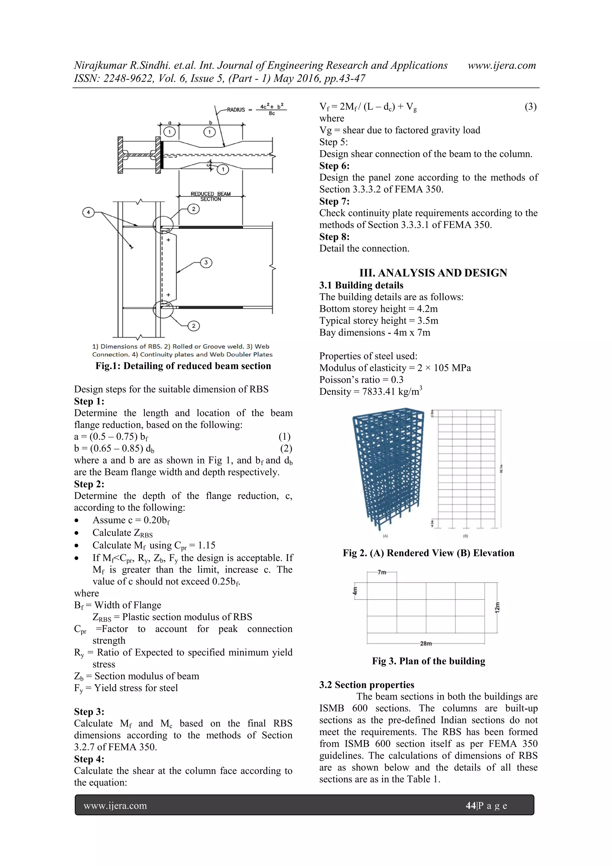
II. GUIDELINES FOR DESIGN OF
REDUCED BEAM SECTION
The guidelines for deciding the dimensions
and design of RBS based on the shear and flexure
parameters have been given in FEMA-350. The
guideline provided in this document is for design of
fully restrained Reduced Beam Section (RBS)
connection. Figure 3.1 provides typical details for
such connections. When connection with RBS is
used, the elastic drift calculations should be
considered the effect of the flange reduction. In lieu
of specific calculations, a drift increase of 9% may
be applied for flange reductions ranging to 50% of
the beam flange width, with linear interpolation for
lesser values of beam flange reduction.
RESEARCH ARTICLE OPEN ACCESS](https://image.slidesharecdn.com/i060501043047-160810114845/75/Study-of-Steel-Moment-Resisting-Frame-with-Reduced-Beam-Section-1-2048.jpg)
![Nirajkumar R.Sindhi. et.al. Int. Journal of Engineering Research and Applications www.ijera.com
ISSN: 2248-9622, Vol. 6, Issue 5, (Part - 1) May 2016, pp.43-47
www.ijera.com 47|P a g e
Fig 11.Storey Drift Plot
RBS being a cut in the regular beam
element reduces the weight of the building. The total
reduction of weight is calculated here to see the cost
benefit of using RBS. Table 5 summarizes the
weights of elements in both the buildings.
Table 5.Material Weight
Element Regular building Building with RBS
Length Weight Length Weight
Column 1134 m 7418.67
kN
1134 m 7418.67
kN
Beam 2752 m 3302.18
kN
2352.3
m
2822.56
kN
RBS - - 399.71
m
366.7 kN
Total 10720.85
kN
10607.93
kN
The difference in weight = 112.92 kN = 11.51 ton.
Considering cost of steel as Rs.65/kg
Cost Benefit = Rs.65000 × 11.51 ton = Rs.7.48 lakhs
IV. CONCLUSION
Following are the important conclusions made
from the present study:
The results show that there has been an increase
in the Time Period of building with RBS by
25% over the building with conventional beams.
The deflection of the top storey of the building
with RBS increases by 23% over the regular
building. The storey drifts also shows an
increase with incorporation of RBS.
There is also a considerable amount of increase
in the storey drift by incorporating RBS.
The difference between base shear of the
building with RBS and without RBS is almost
negligible.
Due to the reduction of beam cross section at
some locations, there is a decrease in structural
steel material. So, there will be a benefit in total
cost of material.
REFERENCES
Journal Papers:
[1] J.shen, T. Kitjasateanphun, W. Srivanich,
“Seismic performance of steel moment
frames with reduced beam sections”,
Engineering Structures 22, pp 968-983,
2000
[2] Jun Jin, Sherif El-Tawil, “Seismic
Performance of Steel Frames with reduced
beam section connections”, Journal of
Constructional Steel Research 61, pp 452-
471, 2005
[3] Swati Ajay Kulkarni, Gaurang Vesmala,“
Study of Steel Moment connection with and
without reduced beam section”, Case
Studies in Structural Engineering 1, pp 26-
31, 2014
[4] Scott M. Adan, Lawrence D.
Reaveley,“The Reduced Beam Section
Moment Connection without Continuity
Plates”,13th World Conference on
Earthquake, 2000
[5] Brandon Chi, Chia-Ming Uang, “Cyclic
response and design recommendations of
reduced beam section moment connections
with deep columns”, Journal of Structural
Engineering, 0733-9445 ,pp 464-472,2002
[6] Scott L jones, Gary T fry, “Reduced beam
section welded steel moment frames”, 13th
World Conference on Earthquake, pp 1671,
2000
[7] K.Kildashti, R.Mirghaderi, I.M.Kani ,“The
efficiency of reduced beam section
connections for reducing residual drifts in
MR Frames”, Open Journal of Civil
Engineering, 2, pp 68-72, 2012
[8] C.E.Sofias, C.N.Kalfas, D.T.Pachoumis,
“Experimental and FEM analysis of
reduced beam section moment endplate
connections under cyclic loading”,
Engineering Structures, 59,pp 320-
329,2014
[9] IS 800-2007, General construction in steel-
code of practice
[10] FEMA 350, Recommenced seismic design
criteria for new steel moment frame
buildings](https://image.slidesharecdn.com/i060501043047-160810114845/75/Study-of-Steel-Moment-Resisting-Frame-with-Reduced-Beam-Section-5-2048.jpg)

This document summarizes a study on modeling and analyzing a 15-story steel building with and without reduced beam sections (RBS) using time history analysis. The study found that using RBS increased the building's time period by 25% and increased deflections and drifts compared to a building with regular beams. However, base shear was nearly identical between the two buildings. While RBS increased deformations, it also reduced the total steel material needed by about 11.5 tons, providing a cost savings of around $7,480. Therefore, RBS can improve seismic performance by shifting plastic hinging away from beam-column connections while also offering a cost benefit from reduced material.


