The document discusses the development and testing of reduced beam section (RBS) moment frame connections as an alternative to pre-Northridge reinforced connections. Initial research focused on constant, tapered, and radius cut RBS designs. Radius cut connections performed best by distributing stresses uniformly and avoiding fractures. Extensive testing showed radius cut RBS connections can develop the required strength and ductility of special moment frames while concentrating inelastic behavior in the reduced beam section away from the column.


![DESIGN OF REDUCED BEAM SECTION (RBS} MOMENT FRAME CONNECTIONS
the recommendations provided below are
capable of safely resisting this level of
moment. As a point of comparison, tests on
pre-Northridge moment connections without
RBS cutouts often show maximum moments
at the face of the column of about 125 per-
cent of M~ or greater (Popov, Stephen 1972;
Tsai, PopoPv 1988; Engelhardt, Husain 1993).
Consequently, the addition of the RBS
cutouts in the beam results in a substantial
reduction in moment at the face of the col-
umn.
Much of the design procedure presented
below follows recommendations of the
Interim Guidelines: Evaluation, Repair, Modi-
fication and Design of Welded Steel Moment
Frame Structures (FEMA 267) (1995) and the
Interim Guidelines Advisory No. 1, Supple-
ment to FEMA 267 (FEMA 267A) (1997), with
several exceptions. Most significant of these
exceptions is that FEMA 267A places a limit
on the maximum stress permitted at the face
of the column equal to ninety percent of the
minimum specified yield stress of the col-
umn. For the case of an A992 (A572 Gr. 50)
column, this results in a limit of 45 ksi. This
limit was established to address concerns
regarding the potential for through-thickness
failures in column flanges. The design proce-
dure limits the maximum stress at the face of
the column to a value on the order of the
actual yield stress of the beam. This excep-
tion to the requirements of FEMA 267A has
been adopted for several reasons. First, spec-
imens designed according to the procedures
described herein have performed well in lab-
oratory tests. Second, satisfying the 45 ksi
stress limit, would result in large flange
cutouts in many cases, or would require sup-
plemental flange reinforcement such as cover
plates or ribs. Further, recently completed
research conducted under the SAC Phase 2
program suggests that the potential for
through-thickness failures is considerably
less than previously thought, and that the
current limit of 45 ksi can most likely be
increased without posing an increase in risk
of fracture initiation.
The design procedure assumes that a
radius cut RBS is provided in both the top
and bottom flanges at the moment connec-
tion at each end of a moment frame beam.
The procedure also assumes the minimum
specified yield stress of the beam is 50 ksi or
less (Gr. 50 beams), and that the minimum
specified yield stress of the column is 50 ksi
or greater (Gr. 50 or Gr. 65 columns).
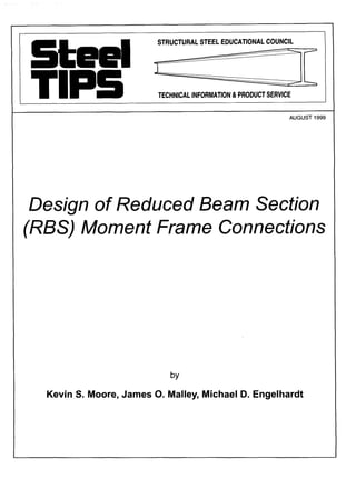
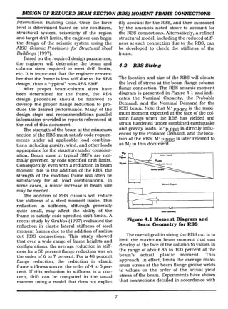
Figure 4.2 shows the geometry of a radius
cut RBS, and Figure 4.3 shows the entire
moment frame beam. The key dimensions
I~ ~1 ~
a
4c~+ d
R = radius of cut
8c
C
~1
--1
b
Figure 4.2
Geometry of Radius Cut RBS
that must be chosen by the designer are a,
the distance from the face of the column to
the start of the RBS cut, b, the length of the
RBS cut, and c, the depth of the RBS cut at
its minimum section. The radius of the cut R
can be related to dimensions b and c based
on the geometry of a circular arc, using the
equation in Fig. 4.2. The amount of flange
material that is removed at the minimum
section of the RBS is sometimes referred to
the percent flange removal which is com-
puted as (2c/bf.) x 100, where bfis the unre-
duced flange v~idth of the beam~
In past research tests, the dimensions a
and b have generally been chosen based on
the judgment of the researchers. In general,
these dimensions should be kept as small as
• w = uniform beam gravity load ~ II II
RBS RBS
__ ~ ~.~_.£1l.~r.! ~ ~ 1 I } I I t ~ ~ 1 t I } ~ l ~ l ~ ~.!?..t.~.!.|~[~]
' &4i i~ ,- ,n -~ ,n - ~
•
,, lla +~ " L' = distancebe~een ~nters of RBS ~ts ~a+ ~ ~
I ~
L : distance between column ¢entedines
Figure 4.3
Typical Moment Frame Beam with
RBS Connections
8](https://image.slidesharecdn.com/seccion-reducida-171005111710/85/Seccion-reducida-11-320.jpg)


![DESIGN OF REDUCED BEAM SECTION (RBS) MOMENT FRAME CONNECTIONS
to the column using either fillet welds or a
CJP groove weld. The shear tab, in turn, is
then welded to the beam web with fillet
welds. An example of such a connection can
be found in "Moment Frame Connection
Development and Testing for the City of Hope
National Medical Center" (Zekioglu, et.al.
1997).
If the engineer chooses to use a bolted
web connection, all aspects of the connection
should be designed to resist the full shear
applied to the beam due to gravity and earth-
quake loads. Short slotted holes may be uti-
lized to futher protect the shear tab and
beam web from possz'bie excesive deflections
when the connection in subjected to large
rotations as the system undergoes inelastic
action during an earthquake. It should be
noted that structural steel erectors prefer
standard holes to slotted holes to aid in erec-
tion.
One of the most discussed aspects of RBS
design, and one of the most important, is the
supplemental lateral bracing required for
this system. FEMA 267A (1997) recommends
that a lateral brace be provided near the
RBS. The following discussion presents an
analysis of test results that did not have lat-
eral bracing provided near the RBS.
Virtually all moment connections that
dissipate energy by yielding of the beam are
subject to varying degrees of beam instability
at large levels of inelastic rotation. This is
true both for reinforced connections (cover
plates, ribs, haunches, etc.) and for RBS con-
nections. This instability generally involves a
combination of flange buckling, web buckling
and lateral torsional buckling and typically
results in deterioration of the beam flexural
strength, with increasing inelastic rotations.
In the experience of some researchers, the
degree of instability and associated strength
deterioration for RBS connections tested in
the laboratory have been no more severe, and
perhaps somewhat less severe than for many
types of reinforced connections. This is
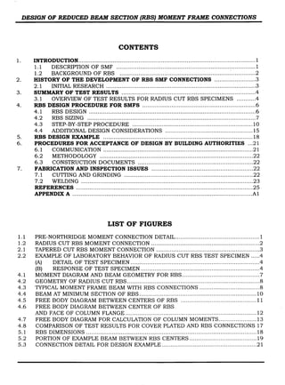
demonstrated by the connection test results
shown in Figure 4.8.
This figure shows a plot of beam tip load
versus beam tip displacement for two differ-
ent test specimens. These two specimens
were virtually identical, except for the con-
nection detail. Both specimens were con-
structed with the same member sizes
(W36xlS0 beam and W14x426 column) and
heats of steel, and tested in the same test
setup with identical member lengths, identi-
cal member end support conditions, and
identical lateral bracing. Both specimens
were subjected to the same loading history.
The only difference was that one specimen
was constructed with a cover plated connec-
tion and the other with an RBS connection.
Both specimens were provided with a single
beam lateral support near the point of load
application.
250
200
150
100 .
~ 50.
~ o.
.~-~0.
-100,
-150.
-200,
-250
-6
Cover'Pla~ed Connectlon ~.______,~_
-~--~--,~
RBS Connection ] * ~
'~ ~ -
_ _ _
- - - -
~ '~"'~'~'({~:;e~
•II
.~ -2
~. ~.~ :~-~
:°~*°" ~~'°~~
, ,
Displacement (inches)
Figure 4.8
Comparison of Test Results for
Cover Plated and RBS Connections
As can be seen from Figure 4.8, the peak
strength of the RBS connection is less than
that of the cover-plated connection. This, of
course, is expected and is in fact a potential
advantage of the RBS in that it reduces the
moment generated at the connection and the
moment delivered to the column. After reach-
ing their peak strength, both connections
exhibited some strength deterioration due to
combined flange, web and lateral torsional
buckling in the beam. Note however that the
rate of deterioration is less for the RBS spec-
imen. In fact, at large inelastic deformations,
the RBS exhibits the same strength as the
cover-plated connection. This comparison
demonstrates the observation made above,
i.e., RBS connections exhibit no more
strength deterioration, and perhaps some-
what less deterioration than reinforced con-
nections.
17](https://image.slidesharecdn.com/seccion-reducida-171005111710/85/Seccion-reducida-20-320.jpg)


![DESIGN OF REDUCED BEAM SECTION (RBS} MOMENT FRAME CONNECTIONS
Vez- 0.8z..,~'Mr 0.8Vc Vc- 0.8x31671 0.8x217=926kips
0.95dt) 0.95×24.26
Panel zone strength is computed as fol-
lows:
From Equation 18:
=0.55F~,~d~tIlL+3b~ft~d+d~t1
I 3x16"23x(2"26)~]
= 0.55xSOx17.12x1.41 1+ 24.26xlT.12xl.41J= 946kips
946 > 926 .'.No doubler plates required
STEP 11 Check Beam Shear
From Equation 19:
w (l-l') /272~222/
V~ 4 2 0.17 -
' 2 143 ÷
2
= 145kips
V, = A,,,Fy = (0.55)(24.26)(5 O) = 667 kips > 145 kips
RBS flange reduction is approximately 43
percent. Consequently, it is expected that the
inclusion of tlae RBS the beams will increase
interstory drift by about 5 percent.
S~e~c Abut
,~
~ .B.U.barto remain
I / ~ ~Remove weldtabs
IE 718"x 6" ~,.~,,.T-~-~'~"r-.~/~ IP
{B.S.) ~ I ! [ I / _1 16 ~WeldB.U.barIocoiutnn
•~l~.l I~ .~_5 .° - - N ....
~ l / *~
I.t' i Iw2,.,,7
~i I.II'i Ig;-~'~-------------~,~,:,,d~,,,~,,~,,oo,~d,~, tose~v asbac i~g C~,~ -- ~
IZ ....ooo,0,.to,.]~,~ ,_~ ~ ~ ,~,~.~ : ~ columnand beam byfabdcato~.
II 5/16 cleanedand inspected
.
Configure platecomes to ~ 17 75" Radius
=.o,o0,...... /.of column GrindSmooth
~ ~ J ~ 1 ~ 2.75"7.3"
2.75"
5/'I'~ NI welds: ET0
~lI groovewelds: electrodes must be rat~;Ifor
'° CVNof atteast20It-fosat -20deg.F.
Allweldingshallconformto AWS D1.1
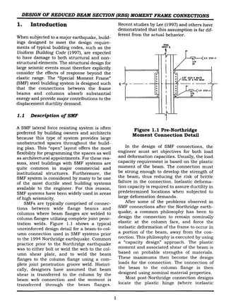
Figure 5.3 Connection Detail for
Design E~mple
6 Procedures for Acceptance
of Design by Building
Authorities
Continuity Plates
Use continuity plates with a thickness
approximately equal to the beam flange
thickness. The beam flange thickness is 0.85
inches. Therefore, use 7/8" thick continuity
plates (0.875"). Connect continuity plates to
column flanges using CJP groove welds, and
the web using double fillet welds. The cor-
ners of continuity plates should be config-
ured to avoid welding into the k-area of the
column.
Beam Web Connection
Connect beam web to column flange
using CJP groove weld over full depth of web
(between weld access holes).
A drawing of a generic final connection
detail is shown in Figure 5.3. The resulting
frame should be checked for all code speci-
fied strength and drift limits. Note that the
The design of SMF building systems require
that the design account for inelastic defor-
mation demands on the connection. The
AISC Seismic Provisions for Structural Steel
Buildings (1997), Section 9.2, presents the
requirements for SMF structures. The RBS
connection is an option that can meet
requirements set by building codes and con-
sensus documents. The following comments
are intended to describe actions that can be
followed to help facilitate the permitting
process for a SMF building system.
6.1 Communication
It is recommended that early in the process,
the Structural Engineer of Record communi-
cate with the building official regarding the
proposed use and pertinent aspects of the
RBS moment connection. The engineer may
need to provide background documentation
to the building official if he or she is unfamil-
iar with the design and terminology relating
21](https://image.slidesharecdn.com/seccion-reducida-171005111710/85/Seccion-reducida-24-320.jpg)


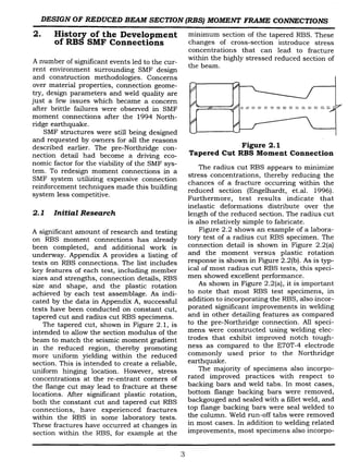
![APPENDIX A
Summary of Experiments on Reduced Beam Section Moment Connections for New Construction
Ref
[1]
[1]
[1]
[1]
[1]
Spec.
YC-1
YC-2
PC-1
PC-2
PC-3
Beam
Built-up W shape
d=23.6", b~=l1.8",
tf=0.79", tw=0.47"
Lb=73"
A36 steel
Fy_f=40 ksi
Fo.~=66 ksi
Fy.w=40 ksi
Fu.w=65 ksi
Column
Built-up Box:
19.7"xl 9.7"x.79"
Lc = 87"
A572 Gr. 50
Fy=56 ksi
Fu=82 ksi
Flange Welds
SS-FCAW
E70T-7
No weld tabs used
Web
Connection
Bolted:
7-7/8" A325
RBS Details
and Other
Flange
Modifications
Tapered cut
L1=2"
LRBS=I3.8"
FR=20%
Tapered cut
L~=2"
LRBS=17.7"
FR=25%
Tapered cut
L1=4.7"
LRBS=I5.7"
FR=34%
Tapered cut
L1=4.7"
LRSS= 17.7"
FR=42%
Tapered cut
L1=4.7"
LRss=I7.7"
FR=42%
Op
(%)
2.4
2.9
4.1
4.8
3.8
Comments
Fracture of beam
flange initiating at weld
access hole
Fracture of beam
flange initiating at weld
access hole
Fracture of beam
flange initiating at weld
access hole
Fracture of beam
flange initiating at weld
access hole
Fracture of beam
flange initiating at weld
access hole
I m~](https://image.slidesharecdn.com/seccion-reducida-171005111710/85/Seccion-reducida-30-320.jpg)
![Ref
[2]
[2]
[2]
[2]
[3,4]
[3,4]
Spec.
DBT-
1A-99-
176
Beam
W30x99
A572 Gr. 50
L~=138"
Column
W14x176
A572 Gr. 50
Lc=168"
Flange Welds
SS-FCAW
E70TG-K2;
backing bar removed
Web
Connection
Bolted:
7-1" A325
RBS Details
and Other
Flange
Modifications
Tapered cut
L1=7.5"
LRBS=20.25''
DBT-
1B-99-
176
DBT-
2A-150-
257
DBT-
2B-150-
257
ARUP-
1
Fy.w= 61.6 ksi
Fu.w= 82.8 ksi
W30x99
A572 Gr. 50
Lb=138"
Fy.w= 51.5 ksi
Fu.w= 72.1 ksi
W36x150
A572 Gr. 50
Lb=138"
F~.w= 60.2 ksi
Fu.w= 72.3 ksi
W36x150
A572 Gr. 50
Lb=138"
Fy.w= 62.9 ksi
Fu.w= 83.1 ksi
W36x150
A572 Gr. 50
Lb=132"
Fy.w=55.6 ksi
Fu.w=70.7 ksi
W14x176
A572 Gr. 50
Lc=168"
Fy.w=55.5 ksi
Fu.w=71.8 ksi
W14x257
A572 Gr. 50
Lc=168"
Fy.w=59.6 ksi
Fu.w=75.2 ksi
W 14x257
A572 Gr. 50
Lc=168"
Fy.w=64.5 ksi
Fu.w=83.2 ksi
W 14x426
A572 Gr. 50
Lc=136"
at bottom flange
SS-FCAW
E70TG-K2
backing bar left in
Bolted:
9-1" A325
welded
(heavy shear
tab groove
FR=45%
Tapered cut
L1=7.5"
LRBS=20.25"
FR=45%
Tapered cut
L1=9"
LaBs=24"
FR=45%
Tapered cut
L1=9"
LRBS=24''
FR=45%
Tapered cut
L1=9"
LABS=24"
COH-1
Fy.f=55.5 ksi
Fu4=73 ksi
Fy.w=62.5 ksi
Fu-w=77 ksi
W27x178
A572 Gr. 50
Lb=132"
Fy.f=44 ksi
Fu.f=62 ksi
Fy.w=46 ksi
Fu-w=62 ksi
W 14x455
A572 Gr. 50
Lc=136"
Fy.f=55 ksi
Fu4=84 ksi
Fy.w=54 ksi
Fu-w=86 ksi
place w/seal weld at
top flange;
backing bar removed
at bottom flange
welded to
column and
fillet welded
to beam
web)
FR=44%
top & bottom
flanges
reinforced with
vertical ribs
Tapered cut
L~=7"
LABS=20"
FR=38%
top & bottom
flanges
reinforced with
vertical ribs
0p
(%)
2.8
4.0
Comments
no failure; test stopped
due to limitations in
test setup
no failure; test stopped
due to limitations in
test setup
3.5 ' Fracture of beam top
flange near groove
we d
1.7 Fracture of beam top
flange we d;
propagated to divot-
type fracture of
column flange
3.5 Flange fracture at
minimum section of
RBS
3.5
A-2](https://image.slidesharecdn.com/seccion-reducida-171005111710/85/Seccion-reducida-31-320.jpg)
![[3,4]
[3,4]
[3,4]
[3,4]
COH-4
~¢ =~
COH-5
|~
[5,6]
[5,6]
Spec. Beam Column Flange Welds Web
Connection
RBS Details
and Other
Flange
Modifications
COH-2
(~ =¢ ~
COH-3 Wl 4x455
A572 Gr. 50
Lc=136"
Fy.f=55 ksi
Fu.f=84 ksi
Fyow=54 ksi
Fu-w=86 ksi
Beam connected to
column web
W33x152
A572 Gr. 50
Lb=132"
Fy.f=57.6 ksi
Fu.f=78.5 ksi
Fy.w=62 ksi
Fu-w=84.5 ksi
Tapered cut
L1=9"
LRBS=26"
FR=43%
top & bottom
flanges
reinforced with
vertical side
plates
Ref
DB1 Wl 4x426
A572 Gr. 50
Lc=136"
W 14x426
A572 Gr. 50
Lc=136"
Fy.f=50 ksi
Fu4=74.5 ksi
Fy.w=50 ksi
Fu.w=75 ksi
W33x152
A572 Gr. 50
Lb=132"
F~4=62.8 ksi
Fu.f=86 ksi
F~.w=69.1 ksi
Fu.w=93.7 ksi
SS-FCAW
E71T-8
backing bar left in
place w/seal weld at
top flange;
backing bar removed
at bottom flange
W36x160
L~=134"
Fy.f=54.7 ksi
Fu4=75.6 ksi
Fy.w=53.5 ksi
Fu-w=79.2 ksi
welded
(beam web
W36x150
Lb=134"
Fy.f=41.4 ksi
Fu4=58.7 ksi
Fy.w=47.1 ksi
Fu-w=61.8 ksi
DB2
Constant cut
L1=9"
groove
welded to
column)
LRBS=I9.5"
FR=40%
Radius cut
L1=9"
L~Bs=27"
FR=40%
Gp Comments
(O/o)
3.8
3.2
4.0
1.8
2.0 Flange fracture at
RBS
3.0 Testing stopped due"
to limitations of test
setup
A-3](https://image.slidesharecdn.com/seccion-reducida-171005111710/85/Seccion-reducida-32-320.jpg)
![Ref
[5,6]
[5,6]
[5,6]
[7]
Spec.
DB3
DB4
DB5
DB1
Beam
W36x170
L~=134"
Fy.f=58 ksi
Fu.f=73 ksi
Fy,w=58.5 ksi
Fu.w=76.7 ksi
W36x194
Lb=134"
Fy.f=38.5 ksi
Fu4=58.6 ksi
Fy,w=43.6 ksi
Fu.w=59.8 ksi
W30x148
Lb=134"
Fy.f=46.6 ksi
Fu.f=64.5 ksi
Fy.w=48.5 ksi
Fu.w=65.4 ksi
W36x135
A36 Steel
Lb=134.5"
Column
W 14x426
A572 Gr. 50
Lc=136"
W 14x426
A572 Gr. 50
Lc=136"
Fy4=50 ksi
Fu4=74.5 ksi
Fy,w=50 ksi
Fu.w=75 ksi
W 14x257
A572 Gr. 50
Lc=136"
Fy.f=48.7 ksi
Fu.f=69 ksi
Fy.w=49.4 ksi
Fu.w=66.2 ksi
W 14x257
with 1-5/16" thk.
cover plates
(cover plates welded
across flanges of
W14x257 to form
box)
A572 Gr, 50
L~=132"
Flange Welds
SS-FCAW
E71T-8
(details of backing
and weld tabs not
available)
Web
Connection
Not
Available
RBS Details
and Other
Flange
Modifications
Radius cut
L1=9"
LRBS=27''
FR=40%
Radius cut
L1=9"
LRBS=27"
FR=38%
Radius cut
L1=5"
LRas=25"
FR=38%
Radius cut
L1=8"
LRBS=28''
FR=40%
~p
(%)
3.8
3.7
4.0
3.0
Comments
Testing stopped due
to limitations of test
setup; significant
column panel zone
yielding
Testing stopped due
to limitations of test
setup
A-4](https://image.slidesharecdn.com/seccion-reducida-171005111710/85/Seccion-reducida-33-320.jpg)
![Ref
[8]
[8]
[8]
[8]
[8]
Spec. Beam Column
S-1
S-2A
SC-1
S-3
S-4
W530x82 (Canadian
Designation)
d=20.8", bf=8.2",
tf=0.52", tw=0.37"
wt.=54 Ib/ft.
Lb=142"
CSA G40.41-350W
steel
Fy.f =52.4 ksi
Fo.f=76.6 ksi
Fy.w=57.5 ksi
Fu.w=81 ksi
(~
W 14x120
A572 Gr. 50
Lc=120"
Flange Welds
SS-FCAW
E71T-8
backing bar left in
place w/seal weld at
top flange;
backing bar removed
at bottom flange
Web
Connection
Bolted:
5-1" A325
RBS Details
and Other
Flange
Modifications
Radius cut
L1=4.7"
LRss=l5.7"
FR=55%
0p
(%)
9.0
3.6
3.4
note
(8)
note
(9)
Comments
Specimen loaded
monotonically; testing
stopped due to
limitations of test
setup
Testing stopped due
to limitations of test
setup
Composite slab
included (6); testing
stopped due to
limitations of test
setup
statically applied
simulated earthquake
loading (7); testing
stopped due to
reaching end of
simulated earthquake
loading; no connection
failure
dynamically applied
simulated earthquake
loading (7); testing
stopped due to
reaching end of
simulated earthquake
loading; no connection
failure
A-5](https://image.slidesharecdn.com/seccion-reducida-171005111710/85/Seccion-reducida-34-320.jpg)
![Ref
[8]
[11]
[11]
[11]
[11]
[12]
[12]
Spec.
SC-2
LS-1
Beam Column
W30x99
A572 Gr. 50
W14x176
A572 Gr. 50
Flange Welds
SS-FCAW
E70T-6
Web
Connection
welded
(Beam web
RBS Details
and Other
Flange
Modifications
Radius cut
L1 = 7"
LS-2
LS-3
LS-4
DBBW
Beam 1
Lb = 141"
Fy.f= 54.0 ksi
Fu4= 71.9 ksi
Fy.w= 58.0 ksi
Fu.w= 74.8 ksi
W36x150
A572 Gr. 50
Lb = 141"
Lc = 150"
Fy.f= 55.5 ksi
Fu4= 74.0 ksi
Fy.w= 54.0 ksi
Fu.w= 73.1 ksi
(~
W 14x398
A572 Gr. 50
Lc = 146"
backing bar left in
place w/seal weld at
top flange;
backing bar removed
at bottom flange
~
SS-FCAW
E70T-6
backing bar left in
groove
welded to
column)
Bolted:
10 - 1" A490
LaBs = 20"
FR = 50%
Radius cut
L1 = 9"
LaBS = 27"
FR = 50%
DBBW
Beam 2m
Fy.f= 54.3 ksi
Fo.f= 68.8 ksi
Fy.w= 59.4 ksi
Fu.w= 72.0 ksi
Fy = 53.0 ksi
Fu = 73.0 ksi
(based on CMTR)
place w/seal weld at
top flange;
backing bar removed
at bottom flange
.
0p
(%)
Note
(9)
Comments
Composite slab
included (6);
dynamically applied
simulated earthquake
loading (6); testing
stopped due to
reaching end of
simulated earthquake
loading; no connection
failure
4.0 No connection failure
+1.0 note (12)
/-5.0
-1.0/ note (12)
+5.0
4.0 No connection failure;
testing stopped due to
limitations of test
setup
4.0 No connection failure;
test stopped due to
limitations of test
setup;
see note (13)
4.0
A-6](https://image.slidesharecdn.com/seccion-reducida-171005111710/85/Seccion-reducida-35-320.jpg)
![Ref
[12]
[12]
[13]
[13]
[13]
[13]
Spec.
DBBW-
C
Beam 1
DBBW-
C
Beam 2
DBWW
Beam 1
DBWW
Beam 2
DBWW
-C
Beam 1
DBWW
-C
Beam 2
Beam Column Flange Welds Web
Connection
W36x150
A572 Gr. 50
Lb= 141"
Fy.f= 54.3 ksi
Fu.f= 68.8 ksi
Fy.w= 59.4 ksi
Fu.w= 72.0 ksi
¢¢
W 14x398
A572 Gr. 50
Lc = 144"
Fv = 53.0 ksi
Fu = 73.0 ksi
(based on CMTR)
SS-FCAW
E70T-6
backing bar left in
place w/seal weld at
top flange;
backing bar removed
at bottom flange
((
welded
(Beam web
groove
welded to
column)
RBS Details
and Other
Flange
Modifications
Op
(%)
5.0
3.8
3.5
Comments
Low cycle fatigue
fracture in RBS;
see note (14)
Fracture of bottom
beam flange adjacent
to groove weld;
fracture initiated at
weld access hole;
see note (14)
No connection failure;
test stopped due to
limitations of test
setup
see note (13)
3.5
5.0 Low cycle fatigue
5.0
fracture in RBS
see note (14)
Low cycle fatigue
fracture in RBS
A-7](https://image.slidesharecdn.com/seccion-reducida-171005111710/85/Seccion-reducida-36-320.jpg)
![Ref Spec.
[14] WG-1
[14] WG-2
[14] WG-3
[14j
Notes:
Beam
W33x201
A572 Gr. 50
Lb = 160.5"
F~.f= 52.0 ksi
Fu-f= 72.8 ksi
Fy.w= 51.5 ksi
Fu-w= 68.0 ksi
W36x300
A572 Gr. 50
Lb = 159"
F~.f= 56.0 ksi
Fu4= 72.9 ksi
Fy.w= 56.7 ksi
Fu.w= 74.5 ksi
WG-4 "
Column
W14x311
A913 Gr. 65
Lc = 152"
Fy.f = 69.0 ksi
Fu4= 88.3 ksi
Fy-w= 68.0 ksi
F..w= 86.5 ksi
5/8" doubler plates
(A572 Gr. 50)
provided on each
side of column web
W14x550
A913 Gr. 65
Lc = 152"
Fy.f= 67.0 ksi
Fu4= 86.8 ksi
Fy.w= 68.1 ksi
Fu.w= 87.6 ksi
Flange Welds
SS-FCAW
E70TG-K2;
backing bar removed
at bottom flange
Web
Connection
Bolted:
13-1" A490
Bolted:
20 - 1" A490
(2 rows of 10
bolts each)
RBS Details
and Other
Flange
Modifications
Radius cut
L1 = 9.3"
LRBS= 25"
FR = 54%
Radius cut
L1 = 10"
Lass = 27"
FR = 51%
~p
(%)
2.9
2.9
3.5
Comments
fracture of RBS at
local buckle in RBS
see note (15)
No connection failure;
test stopped due to
limitations of test
setup
1~
" 4.5 "
1. All specimens are single cantilever type, except DBBW, DBBW-C, DBWW, and DBWW-C
2. All specimens are bare steel, except SC-1, SC-2, DBBW-C and DBWW-C
3. All specimens subject to quasi static cyclic loading, with ATC-24, SAC or similar loading protocol, except S-1, S-3, So4, SC-2, LS-2 and LS-3
4. All specimens provided with continuity plates at beam-to-column connection, except Popov Specimen DB1 (Popov Specimen DB1 was provided with
external flange plates welded to column).
5. Specimens ARUP-1, COH-1 to COH-5, S-1, S-2A, S-3, S-4, SC-1, SC-2 and LS-4 provided with lateral brace near loading point and an additional
lateral brace near RBS; all other specimens provided with lateral brace at loading point only.
6. Composite slab details for Specimens SC-2 and SC-2:118" wide floor slab; 3" ribbed deck (ribs perpendicular to beam) with 2.5" ~oncrete cover;
normal wt. concrete; welded wire mesh reinforcement; 3.4"dia. shear studs spaced at 24" (one stud in every other rib); first stud located at 29" from
face of column; 1" gap left between face of column and slab to minimize composite action.
A-8](https://image.slidesharecdn.com/seccion-reducida-171005111710/85/Seccion-reducida-37-320.jpg)
![7. SpecimensS-3, S-4 and SC-2weresubjectedto simulatedearthquakeloadingbasedon N10Ehorizontalcomponentof the Llolleorecordfrom the
1985ChileEarthquake.For SpecimenS-3,simulatedloadingwas appliedstatically.For SpecimenS-4 and SC-2;simulatedloadingwas applied
dynamically,and repeatedthreetimes.
8. SpecimenS-3: Connectionsustainedstaticsimulatedearthquakeloadingwithoutfailure.Maximumplasticrotationdemandon specimenwas
approximately2%.
9. SpecimensS-4and SC-2:Connectionsustaineddynamicsimulatedearthquakeloadingwithoutfailure.Maximumplasticrotationdemandon
specimenwas approximately2%.
10. Testsconductedby Plumiernot includedin Table.Specimensconsistedof HE 260Abeams(equivalentto W10x49)and HE 300Bcolumns
(equivalentto W12x79).All specimenswereprovidedwithconstantcut RBS.Beamsattachedto columnsusingfillet weldson beamflangesand web,
or usinga boltedend plate.Detailsavailablein Refs.9 and 10.
11. Shakingtabletestswereconductedby Chen,Yehand Chu[1] on a 0.4 scalesinglestorymomentframewith RBSconnections.Framesustained
numerousearthquakerecordswithoutfractureat beam-to-columnconnections.
12. SpecimensLS-2and LS-3weretestedusingnearfield loadingprotocol.The specimenwas subjectedto peakpulsescorrespondingto 6% storydrift
ratio. Loadingwas repeatedsix timesfor LS-2andfourtimesfor LS-3.The specimenseventuallyfaileddueto lowcyclefatiguefractureat the
narrowestsectionin the RBS.
13. SpecimensDBBWand DBWWwerecruciformt~,pespecimenswithbeamsattachedto eachcolumnflange.
14. SpecimensDBBW-Cand DBWW-Cwerecruciformtypespecimenswithcompositefloorslab.Compositeslabdetails:
96" wideslab;2" ribbedmetaldeck (ribsparallelto beam)with3.5"toppingof normalweightconcrete;concretecompressivestrengthat time of
testing= 3600psi for DBBW-Cand 6800psi for DBWW-C;slab reinforcedwith#4 Gr. 60 barsin eachdirection;3.4"dia. shearstudsspacedat 12";
first stud locatedat 36" from face of column(at end of RBS).
15. SpecimensWG-1 to WG-4:Test reportprovidedslightlyconflictingdataon locationalonglengthof beamwheredisplacementwas measured.Values
of plasticrotationreportedaboveare basedon an estimatedlocationfor displacementmeasurements.
A-9](https://image.slidesharecdn.com/seccion-reducida-171005111710/85/Seccion-reducida-38-320.jpg)
![Notation:
Fy.f = flangeyield stressfrom coupontests
Fu_f = flangeultimatestressfromcoupontests
Fy_w = webyield stressfromcoupontests
Fu-w = webultimatestressfromcoupontests
Lb = Lengthof beam,measuredfrom loadapplicationpointto faceof column
Lo = Lengthof column
L~ = distancefromface of columnto startof RBScut
EBBS = lengthof RBScut
FR = FlangeReduction= (areaof flangeremoved/originalflangearea)xl00
(FlangeReductionreportedat narrowestsectionof RBS)
ep = Maximumplastic rotationdevelopedfor at leastonefull cycleof loading,measuredwith respectto the faceof the column(basedon occurrence
of fractureor basedon end of loading)
References:
[1] Chen,S.J., Yeh,C.H.and Chu,J.M,"DuctileSteel Beam-to-ColumnConnectionsfor SeismicResistance,"Journalof Structural Engineering, Vol.
122, No. 11, November 1996, pp. 1292-1299.
[2] Iwankiw, N.R., and Carter, C., "The Dogbone: A New Idea to Chew On," Modern Steel Construction, April 1996.
[3] Zekioglu, A., Mozaffarian, H., and Uang, C.M., "Moment Frame Connection Development and Testing for the City of Hope National Medical Center,"
Building to Last- Proceedings of Structures Congress XV, ASCE, Portland, April 1997.
[4] Zekioglu, A., Mozaffarian, H., Chang, K.L., Uang, C.M. and Noel, S., "Designing After Northridge," Modem Steel Construction, March 1997.
[5] Engelhardt, M.D., Winneberger, T., Zekany, A.J. and Potyraj, T.J., "Experimental Investigation of Dogbone Moment Connections," Proceedings; 1997
National Steel Construction Conference, American Institute of Steel Construction, May 7-9, 1997, Chicago.
[6] Engelhardt, M.D., Winneberger, T., Zekany, A.J. and Potyraj, T.J., "The Dogbone Connection, Part II, Modem Steel Construction, August 1996.
[7] Popov, E.P., Yang, T.S. and Chang, S.P., "Design of Steel MRF Connections Before and After 1994 Northridge Earthquake," International
Conference on Advances in Steel Structures, Hong Kong, December 11-14, 1996. Also in: Engineering Structures, 20(12), 1030-1038, 1998.
[8] Tremblay, R., Tchebotarev, N. and Filiatrault, A., "Seismic Performance of RBS Connections for Steel Moment Resisting Frames: Influence of
Loading Rate and Floor Slab," Proceedings, Stessa '97,August 4-7, 1997, Kyoto, Japan.
[9] Plumier, A., "New Idea for Safe Structures in Seismic Zones," IABSE Symposium - Mixed Structures Including New Materials, Brussels, 1990.
[10] Plumier, A., "The Dogbone: Back to the Future," Engineering Journal, American Institute of Steel Construction, Inc. 2nd Quarter 1997.
[11] Uang, C.M., Unpublished preliminary test reports for SAC Phase 2 RBS tests, University of California at San Diego, December 1998 and February
1999.
[12] Engelhardt, M.D. and Venti, M., Unpublished preliminary test reports for SAC Phase 2 tests, University of Texas at Austin, 1999. "
[13] Fry, G., Unpublished preliminary test reports for SAC Phase 2 tests, Texas A & M University, 1999.
[14] Unpublished report of connection proof tests for building construction project in southern California; project title withheld at request of building owner,
January, 1999.
A-10](https://image.slidesharecdn.com/seccion-reducida-171005111710/85/Seccion-reducida-39-320.jpg)


