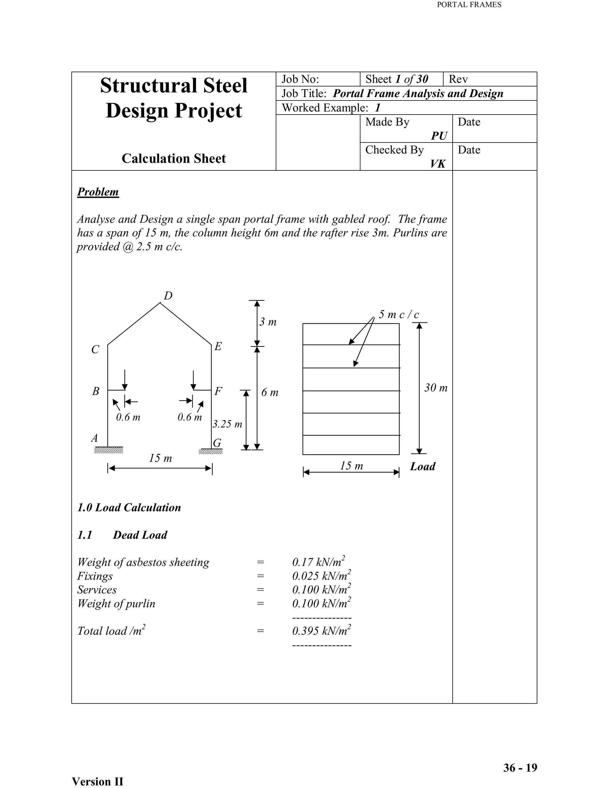
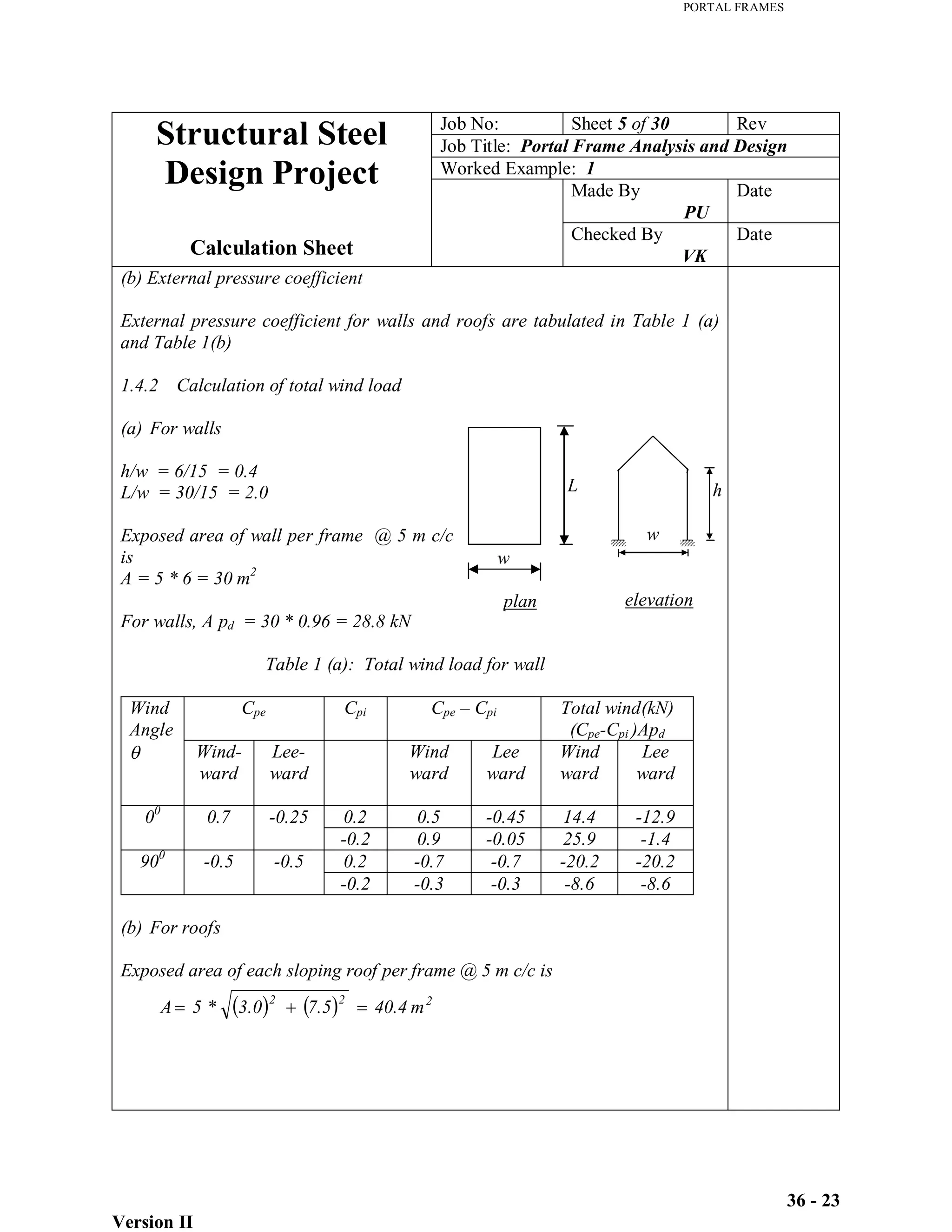
This document provides load calculations and structural analysis for a single span portal frame with a 15 m span, 6 m column height, and 3 m rafter rise. It includes:
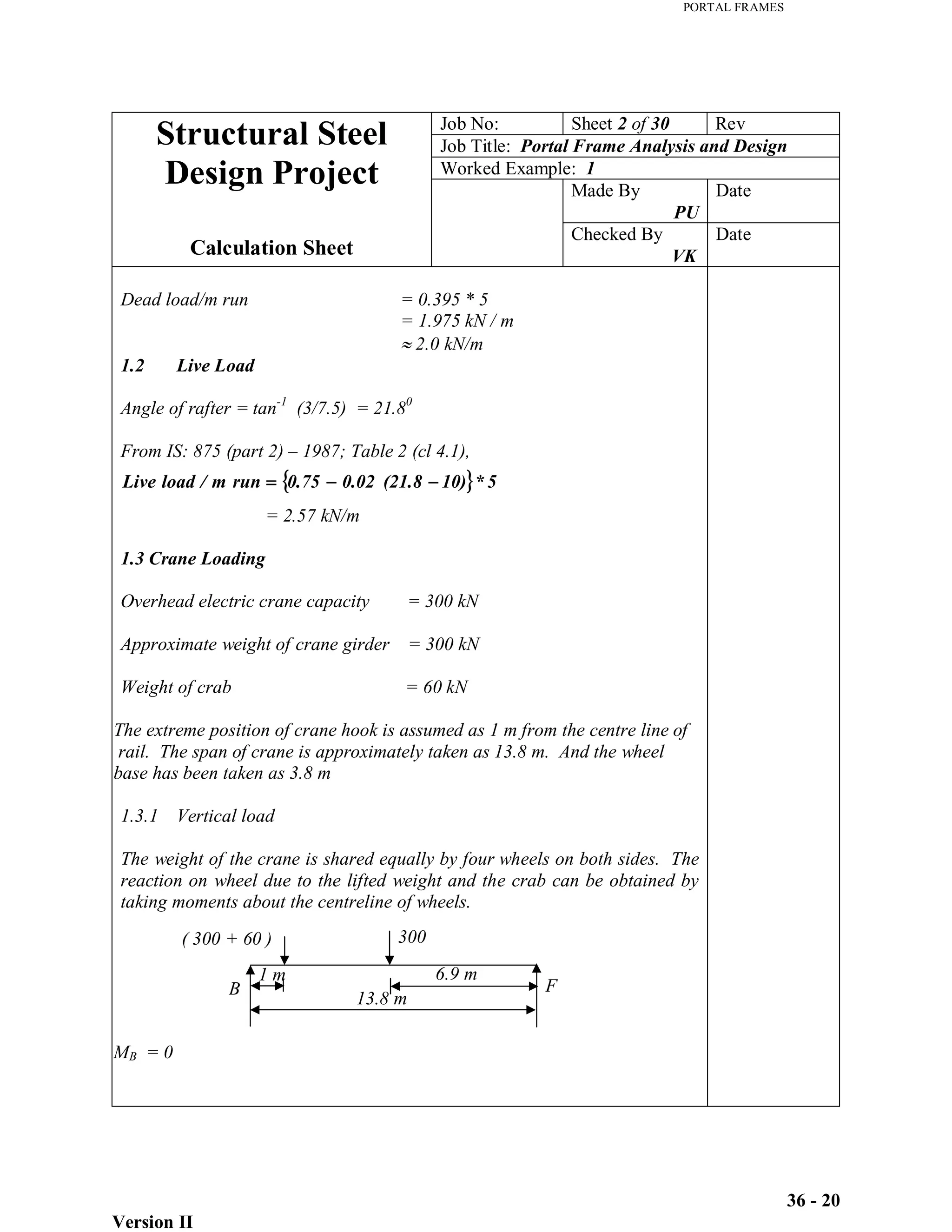
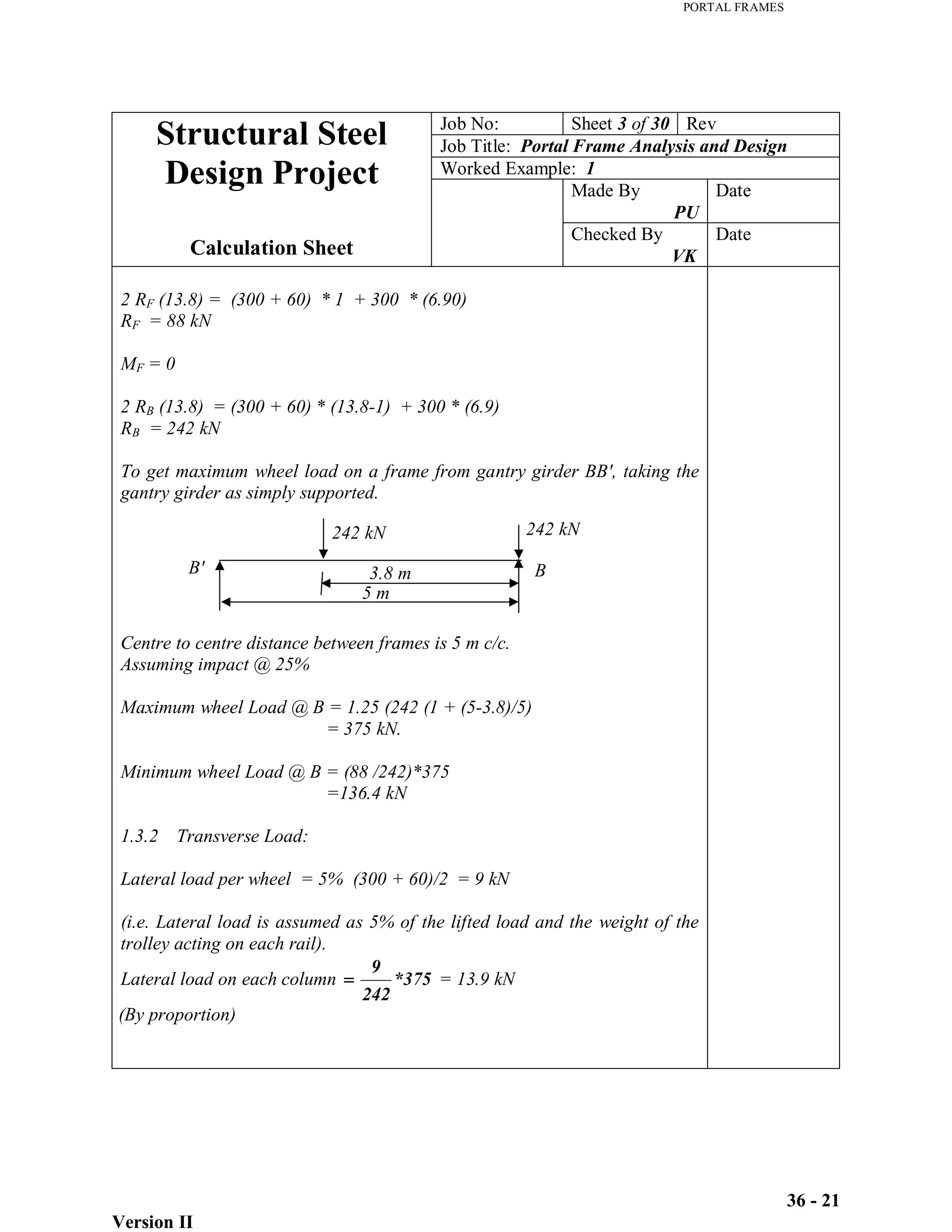
1) Calculation of dead, live, wind, and crane loads. Crane loads include vertical loads up to 375 kN and transverse loads of 13.9 kN.
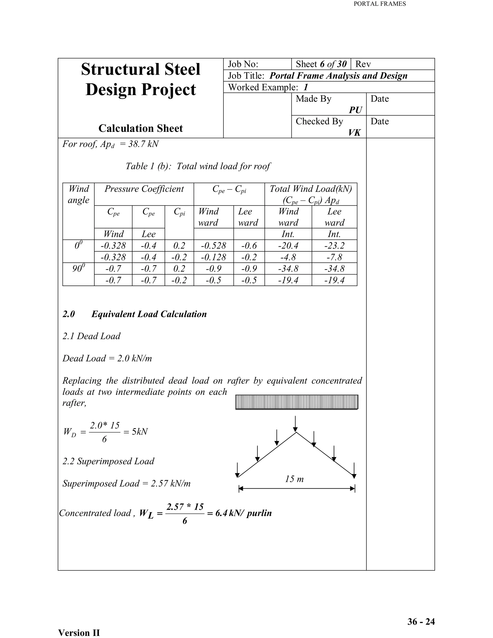
2) Equivalent load calculations to simplify distributed loads.
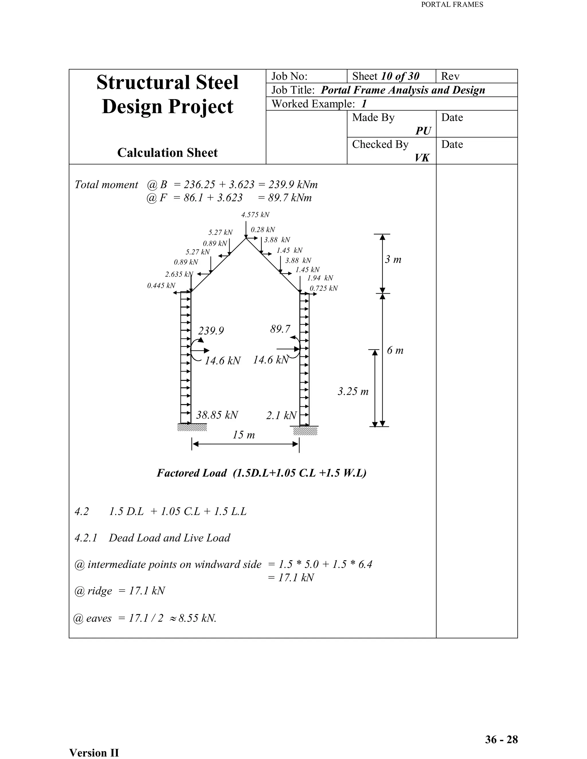
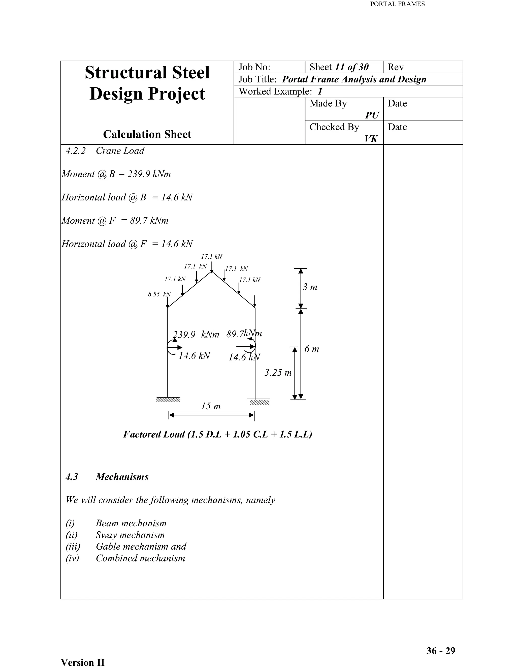
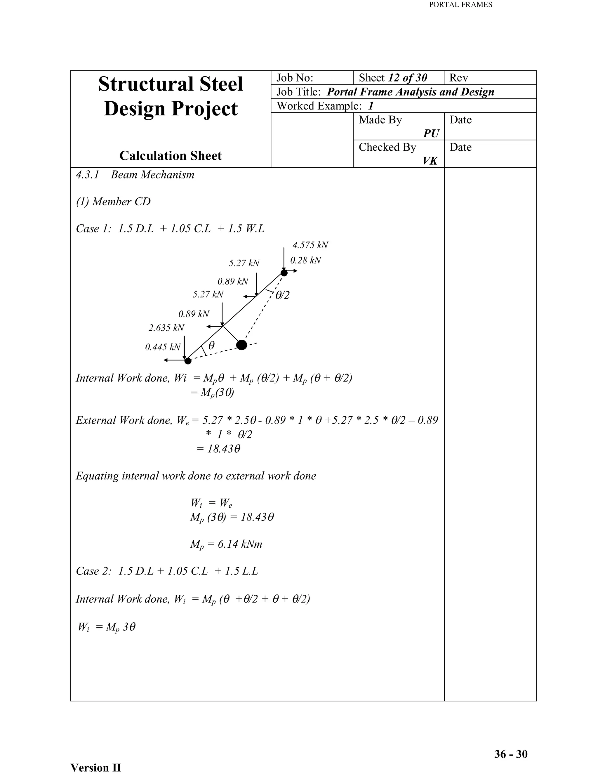
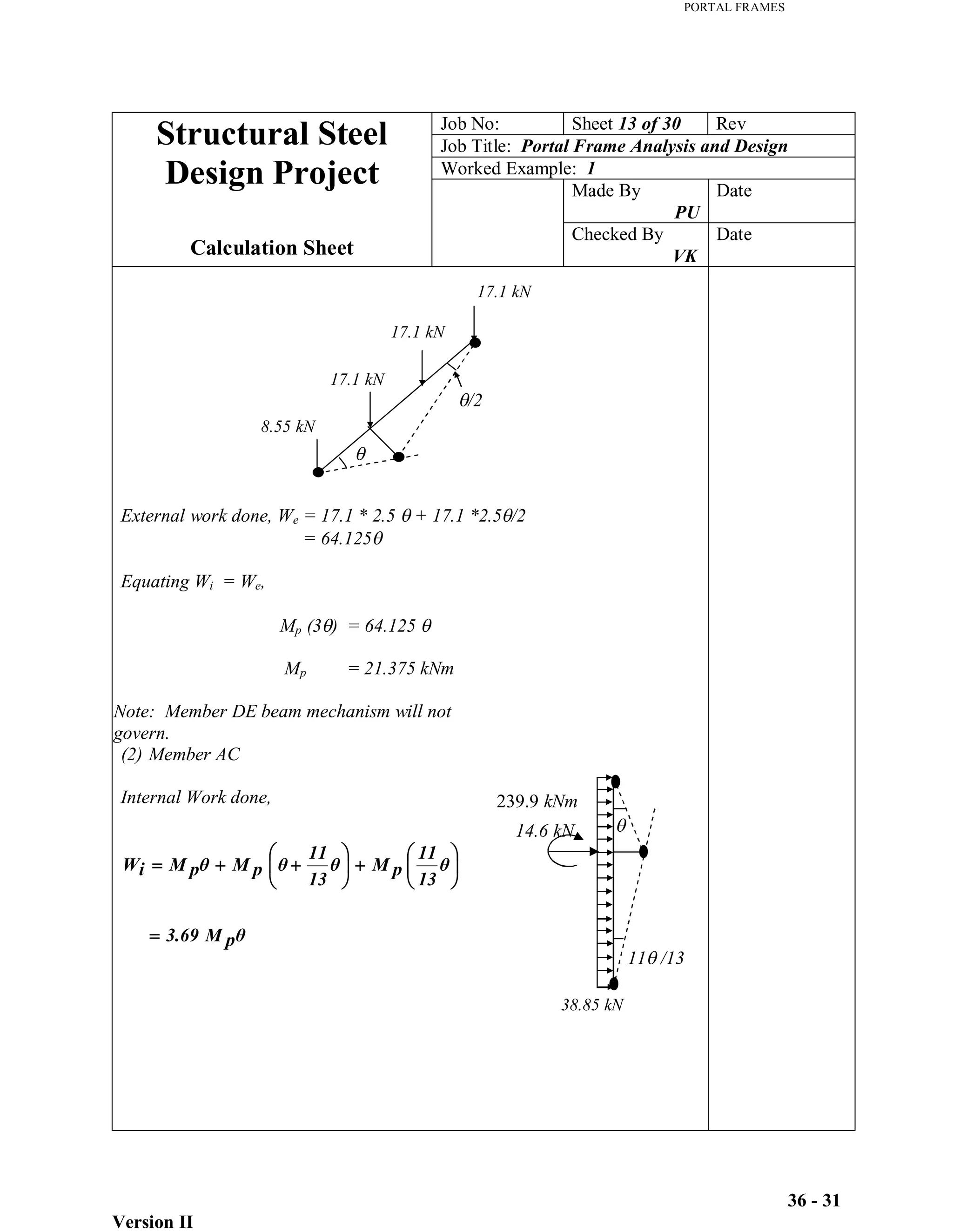
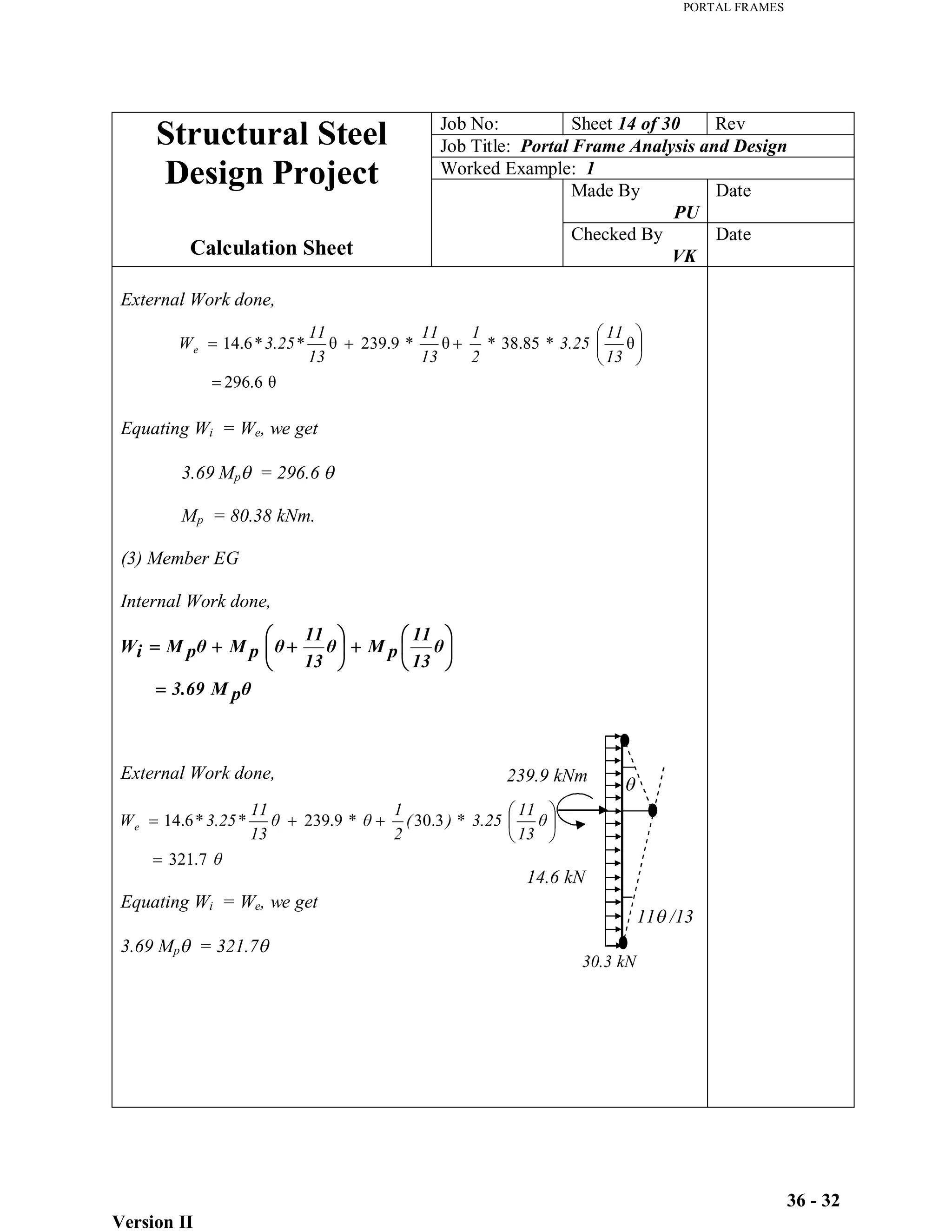
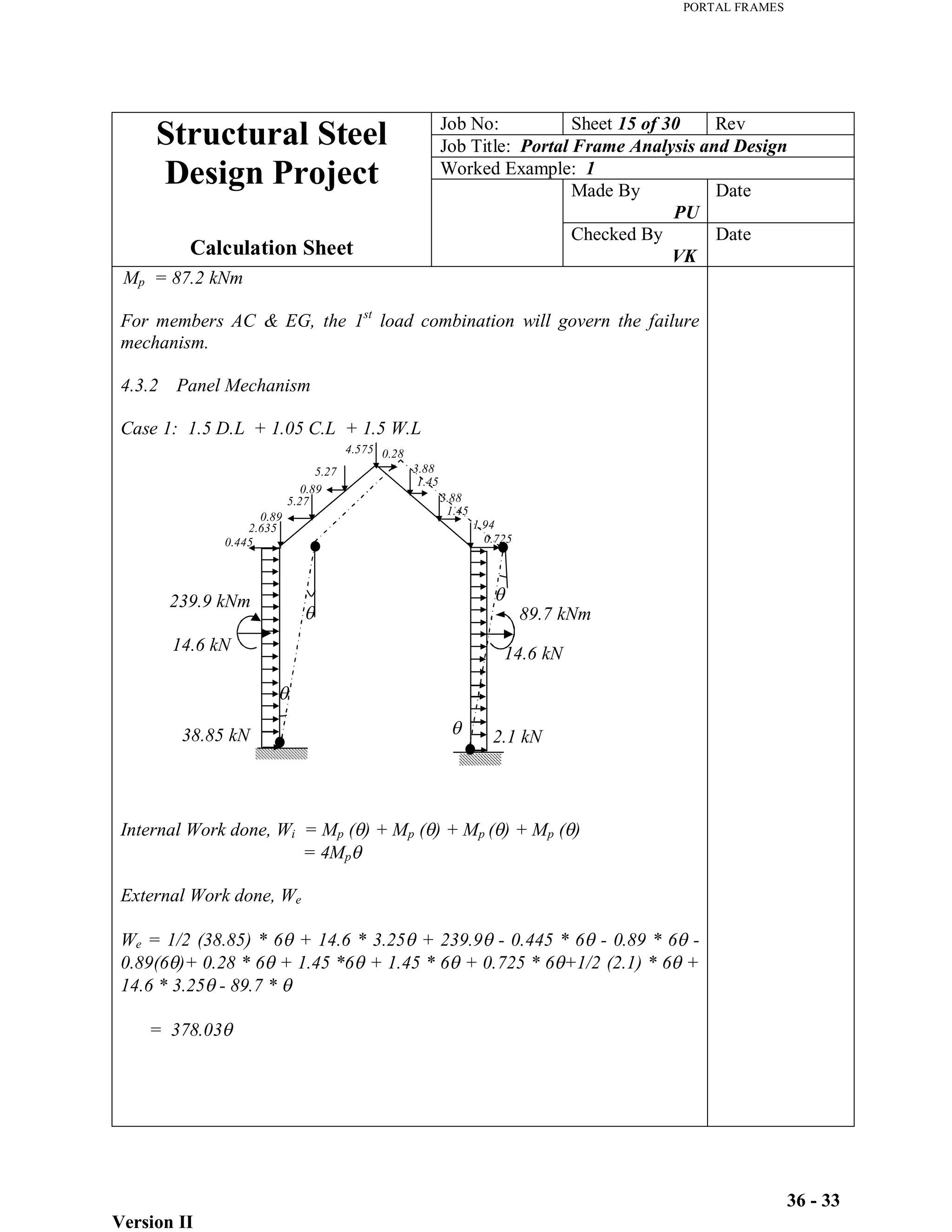
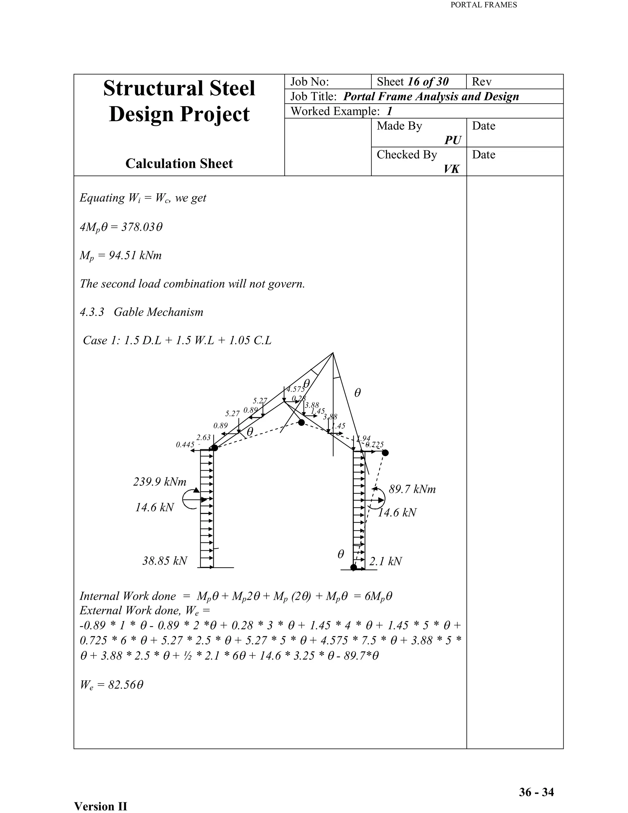
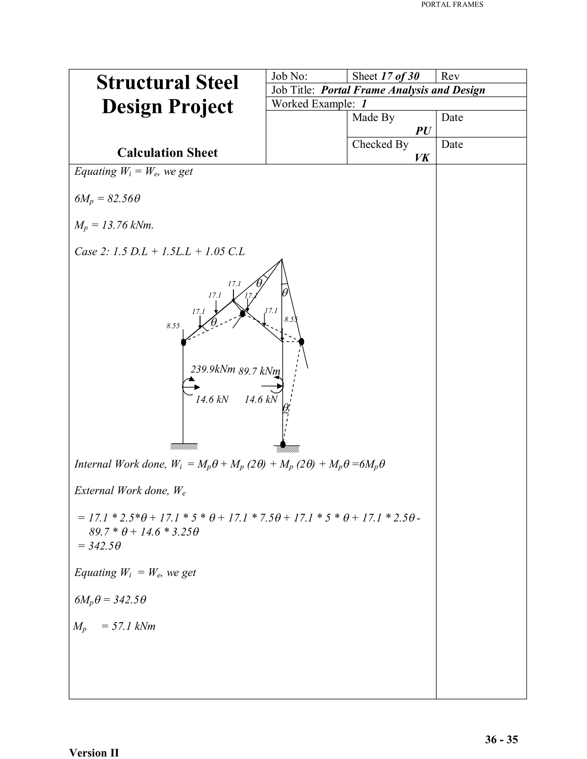
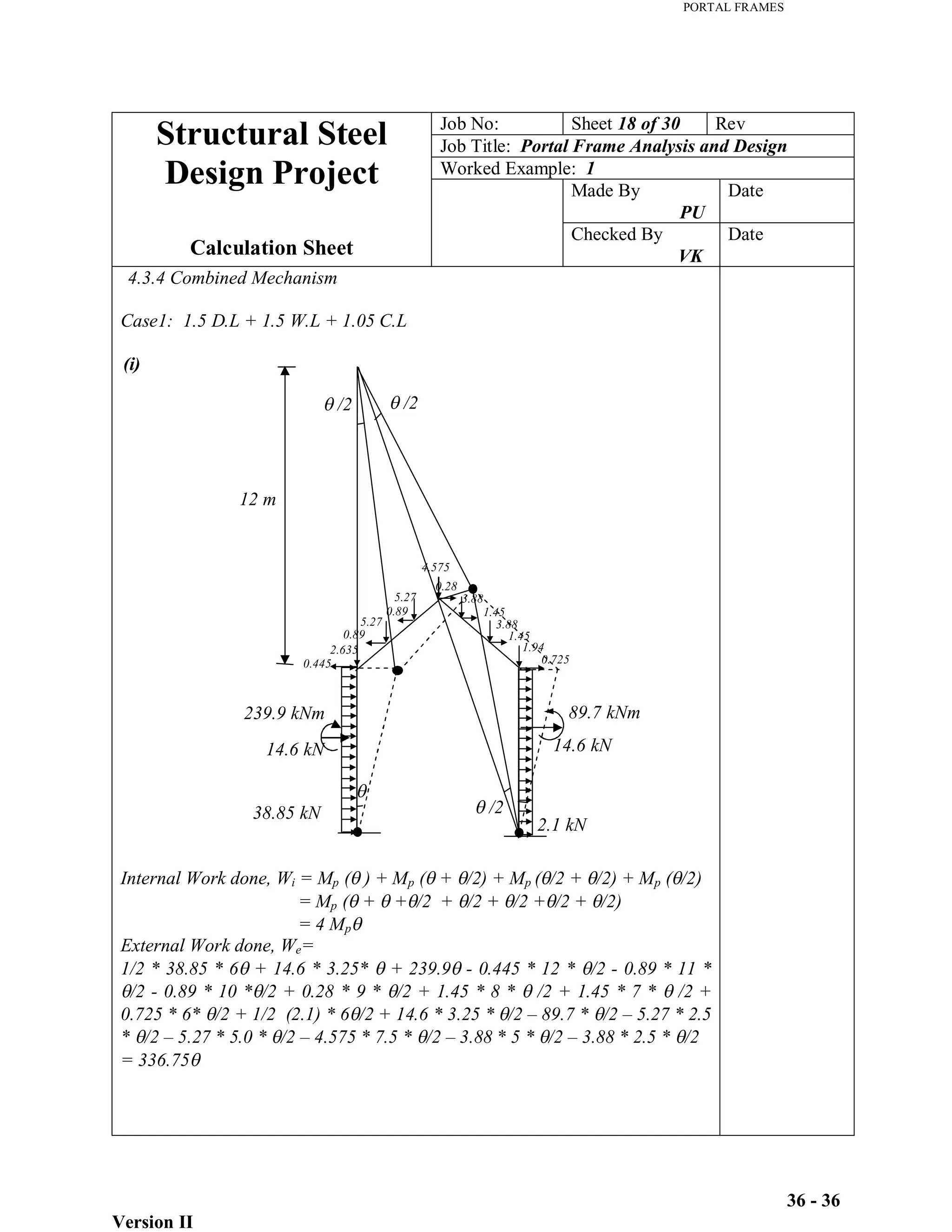
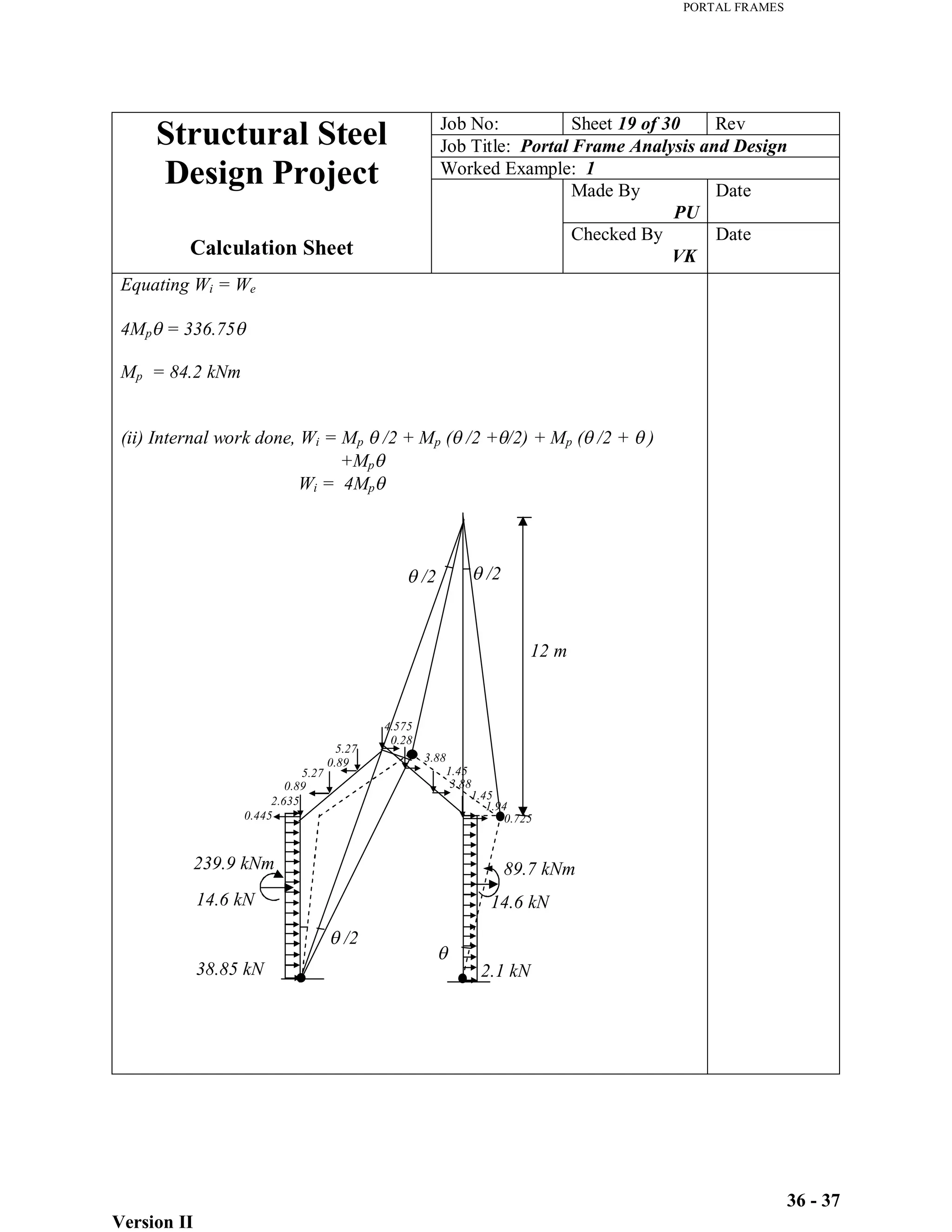
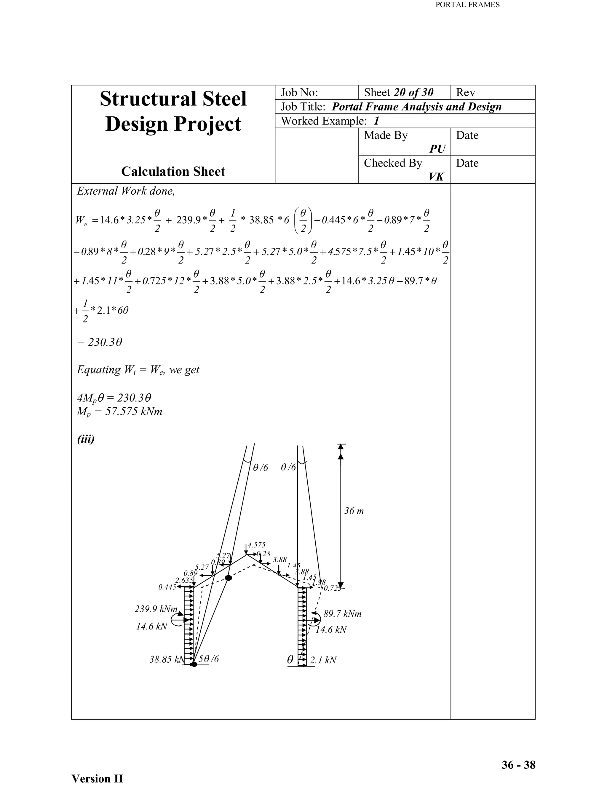
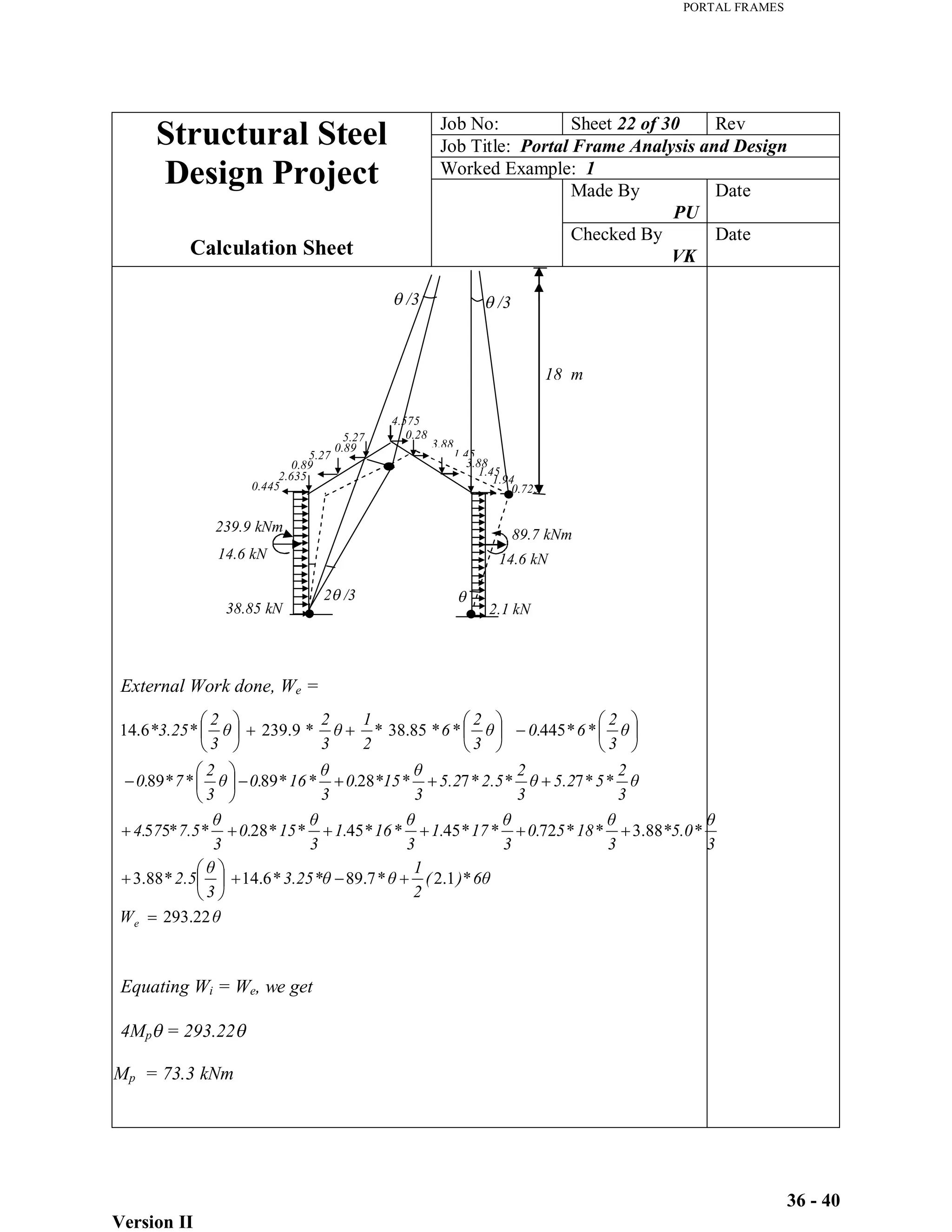
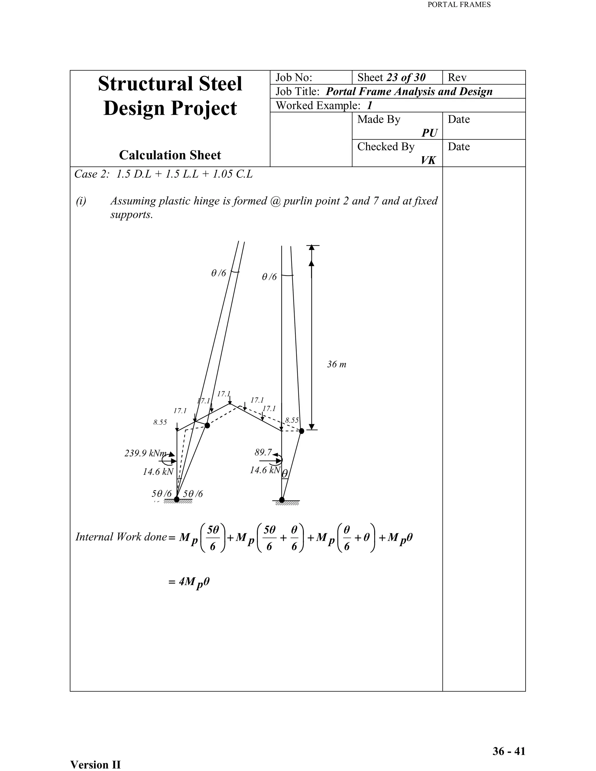
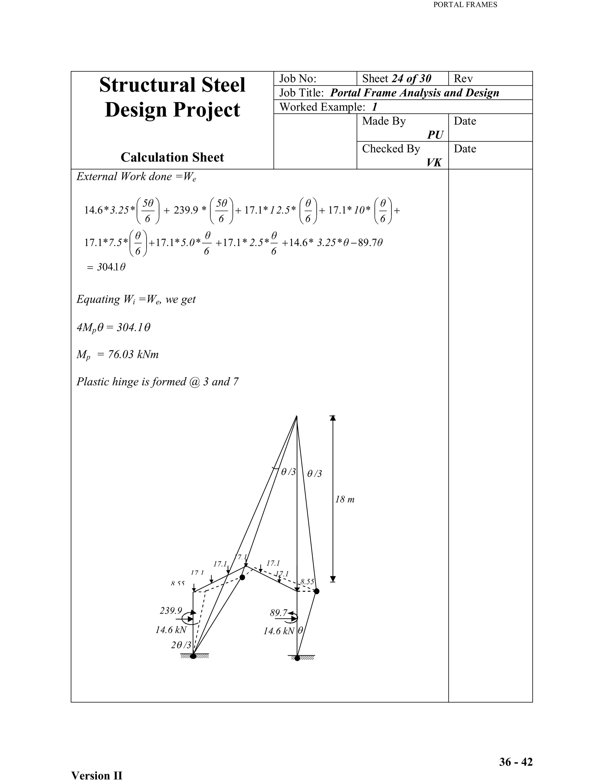
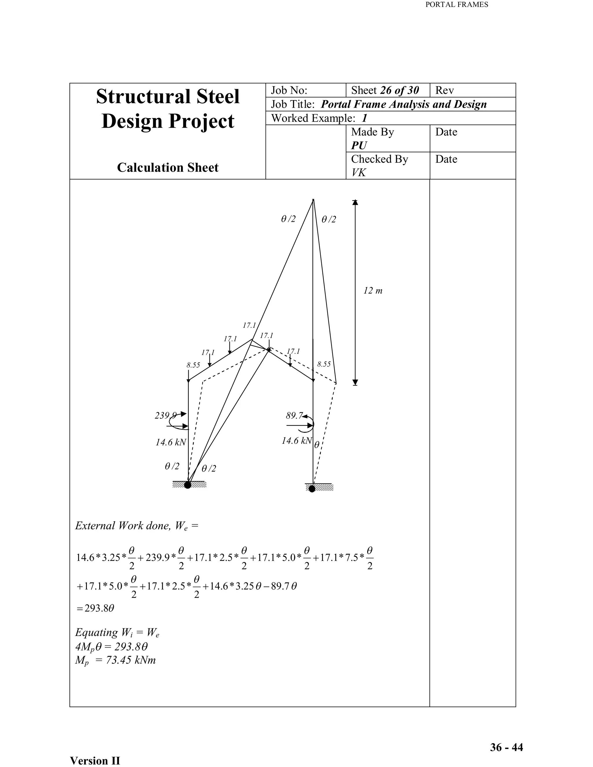
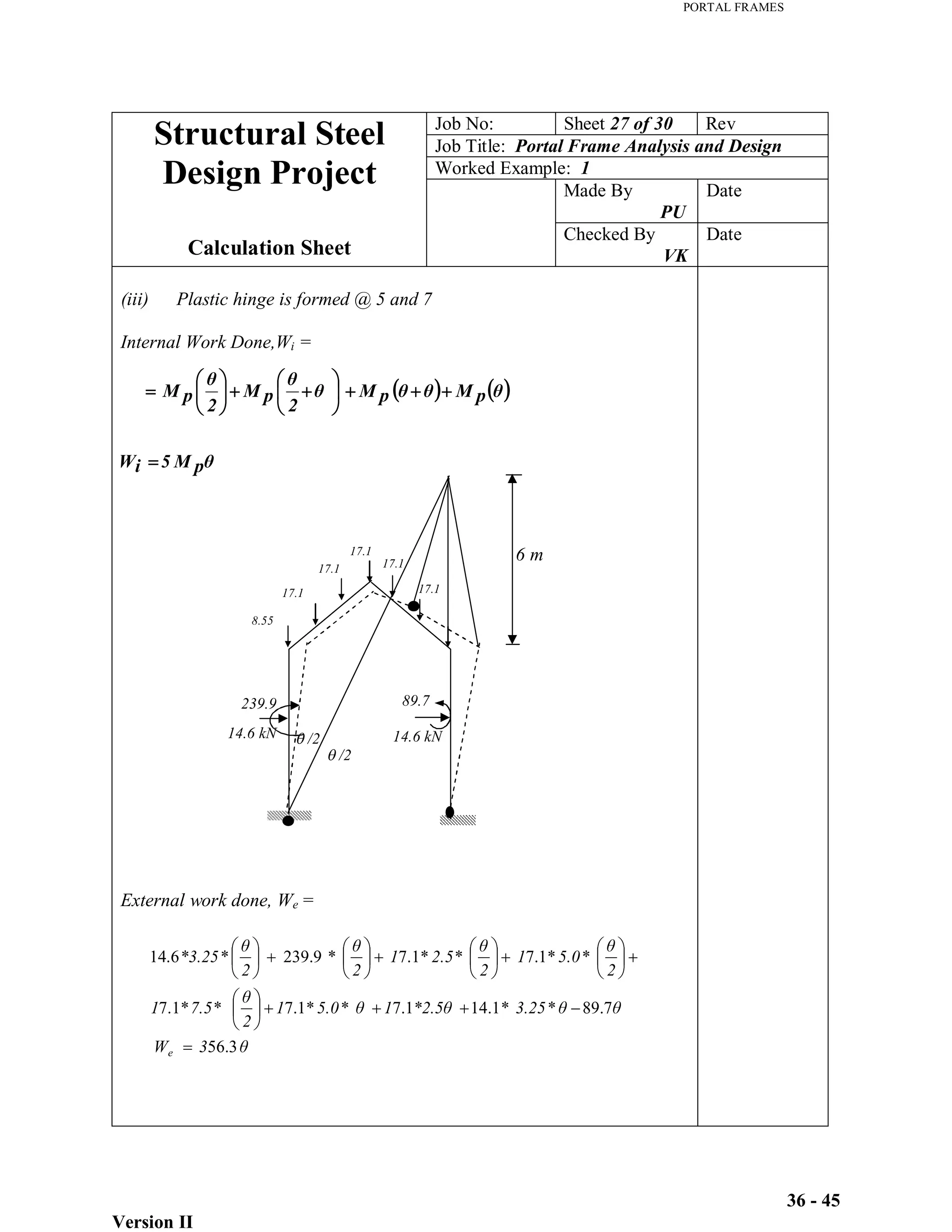
3) Analysis of the frame under key load combinations, considering beam, sway, gable, and combined mechanisms. Moments up to 239.9 kNm and horizontal loads up to 14.6 kN are calculated.
4) Identification of critical load combinations for plastic analysis