Downloaded 16 times


![University of the West of Scotland Civil Engineering
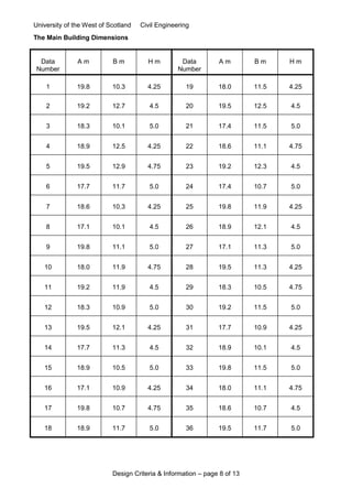
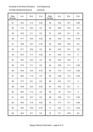
Design Criteria & Information – page 13 of 13
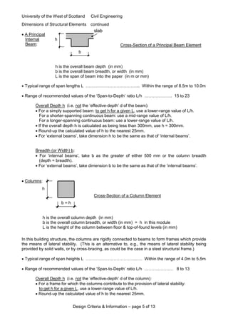
Reinforced Concrete Buildings: Typical Reinforcement Drawings (Element Cross-Sections)
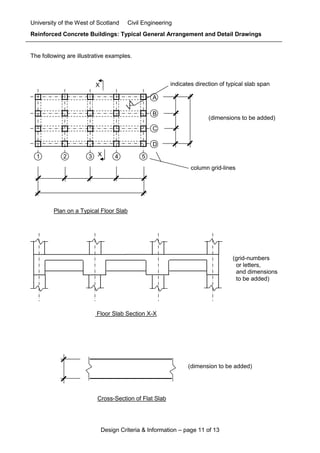
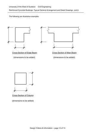
The following are illustrative examples.
Typical range of reinforcing bar diameters used in the UK:
Shear links: 8, 10, 12 & 16mm
Main ‘Tension’ bars: 12, 16, 20, 25, 32 & 40mm
Main ‘Compression’ bars: 12, 16, 20, 25 & 32mm.
H16 shear
links
Edge Beam
(slab reinforcement not shown)
3H12
3H25
H10 shear
links
Column
H12 shear
links
Main Beam
(at a near-midspan section)
[Slab reinforcement not shown]
3H20
5H32](https://image.slidesharecdn.com/pdf3done-160113100624/85/STRUCTURAL-ENGINEERING-13-320.jpg)

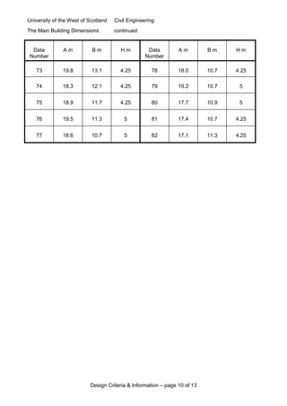
The document outlines the civil engineering design criteria for a reinforced concrete building structure commissioned by a client, detailing the structural frame design responsibilities and client requirements. It specifies the coursework phases for students, covering preliminary sizing, structural loadings, design justification, and final drawings, with an emphasis on flexibility for future use and considerations for the building's function. Additionally, it includes specific guidelines for estimating cross-sectional dimensions, a marking schedule for assessments, and submission requirements for the final report.


