Downloaded 14 times


![2 | P a g e
NOTATION
E = modulus of elasticity of steel = 29,000 kips per square inch (ksi)
Fu = tensile strength, ksi
Fy = yield stress, yield point, or yield strength, ksi
DEFINITIONS
Structural steel, as defined by AISC (in the LRFD Specification and elsewhere), refers to the
steel elements of a structural frame supporting the design loads. It includes steel beams,
columns, beam-columns, hangers, and connections.
Beam-A structural member whose primary function is to carry loads transverse to its
longitudinal axis. Beams are usually horizontal and support the floors in buildings.
Column-A structural member whose primary function is to carry loads in compression along its
longitudinal axis. In building frames, the columns are generally the vertical members which
support the beams.
Beam-column-A structural member whose function is to carry loads both transverse and parallel
to its longitudinal axis. A building column subjected to horizontal forces (such as wind)
is actually a beam-column.
Hanger-A structural member carrying loads in tension along its longitudinal axis.
Connection-The material used to join two or more structural members. Examples of connections
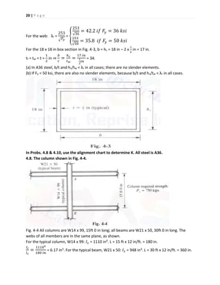
are beam-to-beam and beam-to-column.
MECHANICAL PROPERTIES
The major advantage of steel is its high strength relative to the strengths of the other common
structural materials: wood, masonry, and concrete. Unlike masonry and concrete, which are
weak in tension, steel is strong in both tension and compression. Because of its high strength,
structural steel is widely used in construction. The tallest and longest-span structures are
predominantly steel.
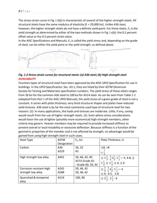
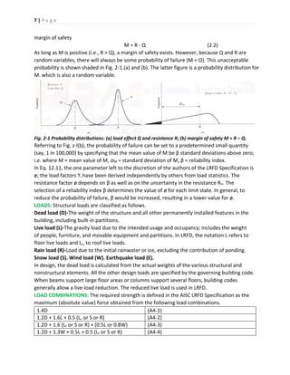
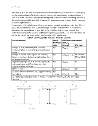
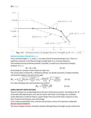
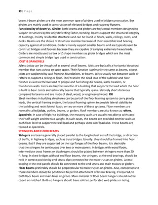
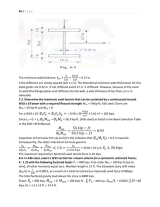
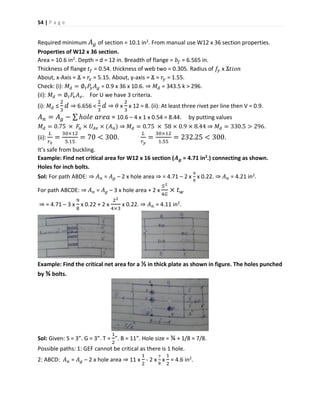
Typical stress-strain curves for structural steel are shown in Fig. 1-2. They are based on the
application of tensile forces to a test specimen. The ordinates (i.e., vertical axes) indicate stress,
which is defined as load divided by cross-sectional area. Units for stress are kips (or kilo pounds;
i.e.,1000 lb) per square inch, commonly noted as ksi. The abscissas (i.e., horizontal axes) indicate
strain, which is a measure of elongation under tension and is defined as the increase in length
divided by the original length. Units for strain are inches per inch; strain is dimensionless.
The stress-strain curve in Fig. 1-2(c) is that of A36 steel, the most commonly used structural
steel. Note the linear relationship between stress and strain in the "elastic range," that is, until
the yield point is reached. The most important design properties of A36 steel [see Fig. 1-2(a)] are
Fy the yield point, the stress at which the proportionality between stress and strain ceases. A36
steel has both an upper and a lower yield point. For design purposes, the yield point of A36 steel
is taken as Fy = 36 ksi, the minimum lower yield point.
Fu, the tensile strength, the maximum stress that the material is capable of sustaining. For 4.36
steel, Fu = 58 to 80 ksi.
E, the modulus of elasticity, which is the (constant) ratio of stress to strain in the elastic ranqe.
For A36 steel, E = 29,000 ksi.](https://image.slidesharecdn.com/steelstructuresce329-190731023301/85/Steel-structures-ce329-2-320.jpg)
![8 | P a g e
1.2D + 1.5E + (0.5L or 0.2S) (A4-5)
0.9D – (1.3W or 1.5E) (A4-6)
[Exception: The load factor on L in combinations (A4-3), (A4-4), and (A4-5) shall equal 1.0 for
garages, areas occupied as places of public assembly, and all areas where the live load is greater
than 100 lb/ft2.]
Loads D, L, L,, S, R, W, and E represent either the loads themselves or the load effects (i.e.,
the forces or moments caused by the loads). In the preceding expressions, only one load
assumes its maximum lifetime value at a time, while the others are at their "arbitrary point-in-
time" values. Each combination models the design loadings condition when a different load is at
its maximum.
Load Combination Load at Its Lifetime Maximum
(A4-1) D (during construction; other loads not present)
(A4-2) L
(A4-3) Lr or S or R (a roof load)
(A4-4) W (acting in the direction of D)
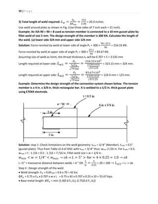
(A4-5) E (acting in the direction of D)
(A4-6) W or E (opposing D)
Load combinations (A4-1) to (A4-6) are for computing strength limit states. In determining
serviceability limit states (e.g., deflections) the un-factored (service) loads are used.
Problems based on the determination of loads
2.1. The moments acting on a floor beam are a dead-load moment of 50 kip-ft and a live-load
moment of 35 kip-ft. Determine the required strength.
Because dead load and floor live load are the only loads acting on the member, Lr = S = R = W =
E = 0. By inspection of formulas (A4-1) to (A4-6), it is obvious that one of the first two formulas
must govern, as follows.
1.4D = 1.4 x 50 kip-ft = 70 kip-ft (A4-1)
1.2D + 1.6L = 1.2 x 50 kip-ft + 1.6 x 35 kip-ft = 116 kip-fl (A4-2)
Because it produces the maximum required strength, the second load combination governs.
The required strength is 116 kip-ft.
2.2. Floor beams W21 x 50, spaced 10 ft 0 in center-to-center, support a superimposed dead
load of 65lb/ft2 and a live load of 40lb/ft2. Determine the governing load combination and the
corresponding factored load.
Total dead load D : 50lb/ft + 65 lb/ft2 x 10.0 ft = 700lb/ft
Total live load L : 40lb/ft2 x 10.0 ft = 400 lb/ft
As in Prob. 2.1, Lr = S = R = W = E = 0.
The two relevant load combinations are
1.4D = 1.4 x 7O0 lb/ft = 980Ib/ft (A4-1)
1.2D + 1.6L = 1.2 x 700lb/ft + 1.6 x 400 lb/ft = 1480 lb/ft (A4-2)
The second load combination, which gives the maximum factored load, 1480lb/ft (or
1.48 kips/ft), governs.](https://image.slidesharecdn.com/steelstructuresce329-190731023301/85/Steel-structures-ce329-8-320.jpg)
![10 | P a g e
DESIGN TENSILE STRENGTH
Two criteria limit the design tensile strength øtPn.
a. For yielding of the gross cross section
øt = 0.90
Pn = FyAg (D1-1)
b. For fracture in the net cross section
øt = 0.75
Pn = FuAe (D1-2)
Where: øt = resistance factor for tension, Pn = nominal axial strength, kips
Fy = specified minimum yield stress, ksi, Fu = specified minimum tensile strength, ksi
Limitation a is intended to prevent excessive elongation of the member. Since the fraction of
the total member length occupied by fastener holes is usually small, the effect of early yielding
of the reduced cross sections on the total elongation of the member is negligible. Hence the
gross section is used. Limit state b deals with fracture at the cross section with the minimum Ae.
DISPLACEMENT
The increase in the length of a member due to axial tension under service loads is
∆ =
Pl
EAg
[3.1]
where: ∆ = axial elongation of the member, in. P = (un-factored) axial tensile force in the
member, kips. l = length of the member, in. E = modulus of elasticity of steel = 29,000 ksi.
PROBLEMS BASED ON THE CROSS-SECTIONAL AREAS OF PLATES
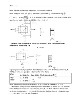
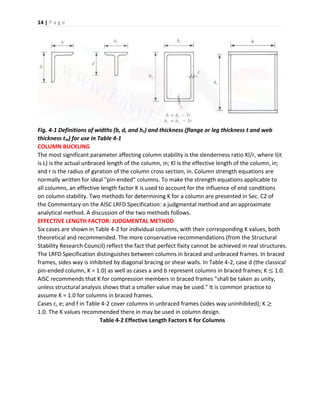
3.1. Determine the gross and net cross-sectional areas of a plate l2inx 2in with a l-in-diameter
hole. (See Fig. 3-2.)
Gross area - gross width x thickness = Ag = 12 in x 2 in = 24 in2.
Net area = net width x thickness, Net width = gross width - hole diameter
For design, hole diameter = 1 in +
1
16
in = 1.06 in
Net width = 12 in - 1.06 in = 10.94 in, An = 10.94 in x 2 in = 21.88 in2.
3.2. Use the same information as in prob 3.1 except with two 1-in diameter holes positioned
as shown in Fig. 3.3.
Gross width of plate = 12 in, Ag = 24 in2. As above.](https://image.slidesharecdn.com/steelstructuresce329-190731023301/85/Steel-structures-ce329-10-320.jpg)
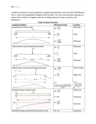
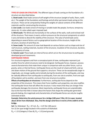
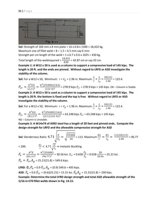
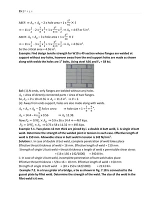
![16 | P a g e
G’ =
(𝐼/𝑙)𝑐1+ (𝐼/𝑙)𝑐2
(𝐼/𝑙)𝑔1+ (𝐼/𝑙)𝑔2
[4.1]
GA K GB
100.0
50.0
30.0
20.0
10.0
9.0
8.0
7.0
6.0
5.0
4.0
3.0
2.0
1.0
0
20.0
10.0
5.0
4.0
3.0
2.0
1.5
1.0
Sidesway uninhibited
100.0
50.0
30.0
20.0
10.0
9.0
8.0
7.0
6.0
5.0
4.0
3.0
2.0
Fig. 4-2 Alignment chart for effective length of columns I unbraced frames having rigid joints.
Table 4-3. Stiffness Reduction Factors for A36 steel for use with Fig. 4-2.
Pu/Ag, ksi SRF Pu/Ag, ksi SRF
30 0.05 20 0.76
29 0.14 19 0.81
28 0.22 18 0.85
27 0.30 17 0.89
26 0.38 16 0.92
25 0.45 15 0.95
24 0.52 14 0.97
23 0.58 13 0.99
22 0.65 12 1.00
21 0.70
Pu is the required strength and Ag is the gross cross sectional area of the subject column.](https://image.slidesharecdn.com/steelstructuresce329-190731023301/85/Steel-structures-ce329-16-320.jpg)
![17 | P a g e
3. Adjust for inelastic column action: GA = G’A x SRF ⇒ GB = G’B x SRF [4.2]
where SRF is the stiffness reduction factor for the column obtained from Table 4-3.
4. For a column end attached to a foundation, G = 10 for a "pin" support and G = 1 for a rigid
support are recommended.
5. Determine K by drawing a straight line from GA to GB on the alignment chart in Fig. 4-2.
DESIGN COMPRESSIVE STRENGTH
Column buckling can be either elastic or inelastic. For design purposes, λc = 1.5 is taken as the
boundary between elastic and inelastic column buckling.
λ 𝑐 =
𝐾𝑙
𝑟𝜋
√
𝐹𝑦
𝐸
(E2-4)
For columns with cross-sectional elements having width-thickness ratios equal to or less than
λr, the design compressive strength is øcPn, where: øc = 0.85
Pn = AgFcr (E2-1)
If λc ≤ 1.5, column buckling is inelastic.
Fcr = (0.658λ 𝑐2
)Fy (E2-2)
Or in the alternate from given in the Commentary on the AISC LFRD Specification
Fcr = [exp(- 0.419λ 𝑐2
)Fy (C-E2-1)
Where exp(x) = ex. If λc ≤ 1.5, column buckling is elastic. Fcr = [
0.877
λ 𝑐2
]Fy (E-2-3)
The terms in these Equations include: λc = slenderness parameter, øc = resistance factor for
compression, Fy = specified minimum yield stress, ksi, Pn = nominal compressive strength, kips,
E = modulus of elasticity of steel = 29,000 ksi. Fcr = critical compressive stress, ksi. Ag = gross
cross-sectional area, in2.
Equation (E2-3) is the Euler equation for column instability multiplied by 0.877 to account for
the initial out-of-straightness of actual columns. Equation (E2-2) & (its equivalent) Eq. (C-E2-1)
are empirical equations for inelastic column buckling, providing a transition from Fcr = Fy at λc =
0 (i.e., Kl/r = 0) to the modified Euler equation [Eq. (E2-3)] for elastic buckling at λc > 1.5. For
A36 steel λc = 1.5 corresponds to a slenderness ratio Kl/r of 133.7.
COLUMN DESIGN
According to Sec. B7 of the AISC LRFD Specification, for compression members KL/r "preferably'
should not exceed 200'". In design, selection of an appropriate column can be facilitated by
referral to tables in one of two ways. The design compressive strengths øcPn of W and other
rolled shapes are tabulated in the AISC LRFD Manual, Part2. Column shapes can be selected
directly from those tables. For built-up sections and rolled shapes not tabulated, Table 4-4 for
A36 steel (and similar tables for other grades of steel in the AISC LFRD Specification) can be
used in iterative design. In both cases, reference to tables replaces the need to solve the
column strength equations [Eqs. (E2-1) ro (E2-4)].
Table 4-4 Design Compressive Stresses for A36 Steel
Design Stress for compression Members of 36 ksi Specified yield-Stress Steel, øc = 0.85*](https://image.slidesharecdn.com/steelstructuresce329-190731023301/85/Steel-structures-ce329-17-320.jpg)
![19 | P a g e
When element width-thickness ratio exceeds λr, see App. B5.3. LFRD Specification.
Reproduced with permission from the AISC LFRD Manual.
Building columns are most commonly W shapes, in the W14-W4 series. The W14 and W12
series are well suited to carrying heavy loads in multistory buildings. The W16 to W40 series are
seldom used for columns because of their inefficiency due to their relatively low values of ry
(the radius of gyration about the weak y axis). The most efficient column sections are structural
shapes with rx = ry (i.e., equal radii of gyration about both principal axes). Included in this
category are pipe and tube shapes, which are often used in lightly loaded single-story
applications. Because they are rolled only with relatively small cross sections, structural pipes
and tubes are not available for carrying heavy column loads.
DISPLACEMENT
The decrease in the length of a member due to axial compression under service loads is
∆=
𝑃𝑙
𝐸𝐴 𝑔
[4.3], Where, ∆ = axial shortening of the member, in. P = (un-factored) axial
compressive force in the member, kips. L = length of the member, in.
Solved Examples
In probs. 4.1 to 4.3, determine whether the given column shape is a slender-element section.
(a) In A36 steel (Fy = 36 ksi) (b) If Fy = 50 ksi.
4.1. W14 x 34. If the width-thickness ratio of an element is greater than λr, it is a slender
element. Referring to Table 4-1 and Fig. 4-1, for the flanges of a W shape.
λr =
95
√ 𝐹𝑦
= {
95
√36
= 15.8 𝑖𝑓 𝐹𝑦 = 36 𝑘𝑠𝑖
95
√50
= 13.4 𝑖𝑓 𝐹𝑦 = 50 𝑘𝑠𝑖
for the web of a W shape: λr =
253
√ 𝐹𝑦
= {
253
√36
= 42.2 𝑖𝑓 𝐹𝑦 = 35 𝑘𝑠𝑖
253
√50
= 35.8 𝑖𝑓 𝐹𝑦 = 50 𝑘𝑠𝑖
From the properties Tables for W shapes, in part 1 of the AISC LFRD Manual (Compact Section
Criteria), for a W14 x 34, flange b/t = bf/2tf = 7.4, web hc/tw = 43.1. Since web (hc/tw = 37.4) < (λr
= 42.2), a W14 x 43 column is not a slender-element section if Fy = 50 ksi.
4.2. W14 x 43. From the properties Tables for W shapes, for a W14 x 43, flange b/t = bf/2tf =
7.5, web hc/tw = 37.4. In A36 steel, flange λr = 42.2. Since flange (b/t = 7.5) < (λr = 15.8) and web
(hc/tw = 37.4) < (λr = 42.2), a W14 x 43 column is not a slender-element section in A36 steel.
(b) However, if Fy = 50 ksi, flange λr = 13.4. web λr = 35.8. Because web (hc/tw = 37.4) < (λr =
42.2), a W14 x 43 column is a slender-element section if Fy = 50 ksi.
4.3. The welded section in Fig. 4-3. Referring to Table 4-1 and Fig. 4-1, for the flanges of a
welded box section.
λ 𝑟 =
238
√ 𝐹𝑦−𝐹𝑟
= {
238
√36−16.5
= 53.9 𝑖𝑓 𝐹𝑦 = 36 𝑘𝑠𝑖
238
√50−16.5
= 41.1 𝑖𝑓 𝐹𝑦 = 50 𝑘𝑠𝑖](https://image.slidesharecdn.com/steelstructuresce329-190731023301/85/Steel-structures-ce329-19-320.jpg)
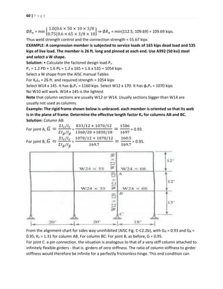
![21 | P a g e
𝐼 𝑔
𝑙 𝑔
=
9844
360 𝑖𝑛
= 2.73 in3. According to Eq. [4.1], the alignment chart parameter
G’ =
(𝐼/𝑙)𝑐1+ (𝐼/𝑙)𝑐2
(𝐼/𝑙)𝑔1+ (𝐼/𝑙)𝑔2
, At both the upper (A) and lower (B) joints: GA = GB =
2×6.17𝑖𝑛3
2×2.73𝑖𝑛3
= 2.26.
From Eq. [4.2], G = G' x SRF. Determining SRF (the stiffness reduction factor):
𝑃 𝑢
𝐴 𝑔
=
750 𝑘𝑖𝑝𝑠
29.1𝑖𝑛2
= 25.8 ksi. Interpolating in Table 4-3, SRF = 0.39. At joints A and B, GA = GB = G' x
SRF = 2.26 x 0.39 = 0.88. in. Fig. 4-2, a straight line drawn from GA = 0.88 to GB = 0.88 intersects
with K: 1.3.
4.10. The column shown in Fig. 4-5. Column connection to the footing is (a) rigid, (b) pinned.
The W10 x 33 column is 12ft 0in high; the W16 x 26 beam is 30ft 0 in long. The webs of the
column and the beam are in the plane of the frame.
Fig. 4-5.
For the W10 x 33 column: 𝐼 𝑥 = 170 in4. L = 12 ft x 12 in/ft. = 144 in.
𝐼 𝑐
𝑙 𝑐
=
1704
144 𝑖𝑛
= 1.18 in3. For the W16 x 36 beam: 𝐼 𝑥 = 301 in4. L = 30 ft x 12 in/ft. = 360 in.
𝐼 𝑐
𝑙 𝑐
=
3014
360 𝑖𝑛
= 0.84 in3. From Eq. [4.1], G’A = 1.18/0.84 = 1.41.
𝑃 𝑢
𝐴 𝑔
=
200 𝑘𝑖𝑝𝑠
9.71𝑖𝑛2
= 20.6 ksi.
From Table 4-3, by Interpolating, SRF = 0.72. At joint A, and GA = G’A x SRF = 1.41 x 0.72 = 1.02.
(a) For rigid attachment to the foundation, GB = 1.0. K = 1.3 in Fig. 4-2.
(b) For pin connection to the foundation, GB = 10. Drawing a line in Fig. 4-2 from GA = 1.02 to
GB = 10 indicates that K = 1.9.
4.11. In A36 steel, select a 6-in pipe (see Table 4-5) for a required axial compressive strength of
200 kips; KL = 10.0 ft.
Table 4-5 (6-in Pipe Sections)
A, in2 r, in
Standard Weight 5.58 2.25
Extra strong 8.40 2.19
Double extra strong 15.60 2.06
Try a 6-in standard weight pipe:
𝐾𝑙
𝑟
=
10 𝑓𝑡 ×12𝑖𝑛/𝑓𝑡
2.25 𝑖𝑛
= 53.3. From Table 4-4 by interpolation,
∅ 𝑐 𝑃𝑛 = 26.34ksi. The design strength for this pipe, ∅ 𝑐 𝑃𝑛 = ∅ 𝑐 𝐹𝑐𝑟 = 𝐴 𝑔= 26.34 kips x 5.58 in2 =
147 kips < 200 kips required. Try a 6-in extra strong pipe:](https://image.slidesharecdn.com/steelstructuresce329-190731023301/85/Steel-structures-ce329-21-320.jpg)
![25 | P a g e
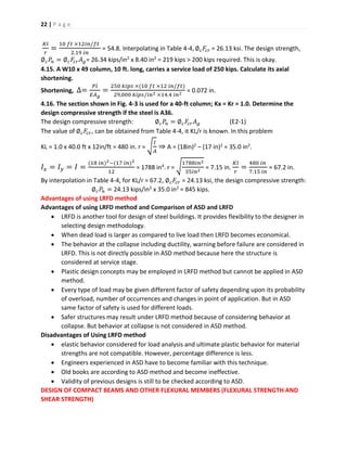
Fig. 5-4 Idealized stress-strain diagram for structural steel
The plastic hinge condition (under which the entire cross section has yielded) represents the
absolute limit of usefulness of the cross section. Only beams which are compact (i.e., not
susceptible to local buckling) and adequately braced (to prevent lateral-torsional buckling) can
attain this upper limit of flexural strength.
The relationships between moment and maximum (extreme fiber) bending stresses, tension or
compression, at a given cross section have been derived in a number of engineering mechanics
textbooks. At the various stages of loading, they are as follows:
Until initial yielding M = Sfb [5.1]
At initial yielding Mr = SFy [5.2]
At full plasticization (i.e. plastic hinge) Mp = ZFy [5.3]
Because of the presence of residual stresses Fr (prior to loading, as a result of uneven cooling
after rolling of the steel member), yielding actually begins at an applied stress of Fy – Fr.
Equation [5.2] should be modified to
Mr = S(Fy – Fr) [5.4]
Equation [5.3] is still valid, however. The plastic moment is not affected by residual stresses.
(Because of their existence in a zero-moment condition before the application of loads, the
tensile and compressive residual stresses must be in equilibrium.)
The terms in Eqs. [5.1] to [5.4] are defined as:
M = bending moment due to the applied loads, kip-in. Mr = bending moment at initial yielding,
kip-in. Mp = plastic moment, kip-in. S = elastic section modulus, in3. Z = plastic section modulus,
in3. Fb = maximum normal stress due to bending, ksi. Fy = specified minimum yield stress, ksi. Fr
= the maximum compressive residual stress in either flange; 10 ksi for rolled shapes;
16.5 ksi for welded shapes.
Elastic section modulus S =
1
𝑐
where I is the moment of inertia of the cross section about its centroid axis, in4; and c is the
distance from the centroid to the extreme fiber, in. The Properties Tables in Part 1 of the AISC
LRFD Manual include the values of I, S, and Z for all the rolled shapes listed.
ELASTIC VERSUS PLASTIC ANALYSIS
Design by either elastic or plastic analysis is permitted by the AISC LRFD Specification (Sec.
A5.1). The more popular elastic analysis has been adopted throughout this text. When an
elastic analysis procedure (such as moment distribution or a typical frame analysis computer
program) is used, the factored moments are obtained assuming linear elastic behavior.
Although this assumption is incorrect at the strength limit states, the fact that elastic analysis is
less complex and is valid under normal service loads has led to its widespread use.
Several restrictions have been placed on plastic design. They are stated in the AISC LRFD
Specification in Secs. A5.1, 85.2, C2.2, EL.2, FL.1, H1.2, and I1.
DESIGN FLEXURAL STRENGTH: Cb = 1.0, Lb ≤ Lr
The design strength of flexural members is øbMn, where do øb = 0.90. For compact sections, the
design bending strength is governed by the limit state of lateral-torsional buckling. As the name](https://image.slidesharecdn.com/steelstructuresce329-190731023301/85/Steel-structures-ce329-25-320.jpg)
![26 | P a g e
implies, lateral-torsional buckling is an overall instability condition of a beam involving the
simultaneous twisting of the member and lateral buckling of the compression flange. To
prevent lateral-torsional buckling, a beam must be braced at certain intervals against either
twisting of the cross section or lateral displacement of the compression flange. Unlike the
bracing of columns (which requires another structural member framing into the column), the
bracing of beams to prevent lateral-torsional buckling can be minimal. Even the intermittent
welding of a metal (floor or roof) deck to the beam may be sufficient bracing for this purpose.
The equations for the nominal flexural strength Mn follow from the preceding discussion of
flexural behavior. Length Lb is defined as the distance between points of bracing. Compact
shapes bending about their minor (or y) axes will not buckle before developing a plastic hinge.
Mny = Mpy = ZyFy [5.6]
For bending about the minor axis regardless of Lb. Compact sections bending about their major
(or x) axes will also develop their full plastic moment capacity without buckling, if Lb ≤ Lp.
Mnx = Mpx = ZxFy [5.7]
For bending about the major axis if Lb ≤ Lp.
Mnx = Mrx = Sx(Fy – Fr) [5.8]
For bending about the major axis if Lb = Lr. If Lp < Lb < Lr, Mn for bending about the major axis is
determined by linear interpolation between Eqs. [5.7] and [5.8]:
𝑀 𝑛𝑥 = 𝑀 𝑝𝑥 − (𝑀 𝑝𝑥 − 𝑀𝑟)= (
𝐿 𝑏−𝐿 𝑝
𝐿 𝑟−𝐿 𝑝
) [5.9]
In the foregoing: Zy = plastic section modulus with respect to the minor centroid (or y) axis, in3
Zx = plastic section modulus with respect to the major centroid (or x) axis, in3
Sx = elastic section modulus with respect to the major centroid (or x) axis, in3
Lengths Lp and Lr are defined in Sec. F1.2 of the AISC LRFD Specification as follows.
For l-shaped sections and channels bending about their major axis
𝐿 𝑝 =
300𝑟 𝑦
√ 𝐹𝑦
(F1-4)
For solid rectangular bars and box beams: 𝐿 𝑝 =
300𝑟 𝑦
𝑀 𝑝
√𝐽𝐴 (F1-5)
where: ry = the radius of gyration with respect to the minor centroid (or y) axis, in
A = cross-sectional area, in2, J = torsional constant, in4
The limiting laterally unbraced length Lr and the corresponding buckling moment Mr are
determined as follows: For I-shaped sections, doubly symmetric and singly symmetric with the
compression flange larger than or equal to the tension flange, and channels loaded in the plane
of the web: 𝐿 𝑟 =
𝑟 𝑦𝑋1
𝐹𝑦−𝐹𝑟
√1 + 𝑋2(𝐹𝑦 − 𝐹𝑟)2 (F1-5)
𝑀𝑟 = (𝐹𝑦 − 𝐹𝑟)𝑆 𝑥 (F1-7)
Where, 𝑋1 =
𝜋
𝑆 𝑥
√
𝐸𝐺𝐽𝐴
2
(F1-8). & 𝑋2 = 4
𝐶 𝑤
𝐼 𝑦
(
𝑆 𝑥
𝐺𝐽
)2
(F1-9)
where](https://image.slidesharecdn.com/steelstructuresce329-190731023301/85/Steel-structures-ce329-26-320.jpg)
![27 | P a g e
E = modulus of elasticity of steel = 29,000 ksi, G = shear modulus of elasticity of steel: 11,200
ksi, Iy = moment of inertia about the minor centroidal (or y) axis, in4, Cw = warping constant, in6.
For symmetric box sections bending about the major axis and loaded in the plane of symmetry,
Mr and Lr shall be determined from formulas (F1-7) and (F1-10), respectively.
For solid rectangular bars bending about the major axis.
𝐿 𝑟 =
57,000𝑟 𝑦
𝑀 𝑟
√𝐽𝐴 (F1-10) & 𝑀𝑟 = 𝐹𝑦 𝑆 𝑥 (F1-11)
Values of J and Cw for many structural shapes are listed in Torsion Properties Tables in Part 1 of
the AISC LRFD Manual.
The practical design of steel beams (Cb = 1.0) can best be done graphically by (1) reference to
the beam graphs in the section entitled Design Moments in Beams, in Part 3 of the AISC LRFD
Manual, where øbMn is plotted versus Lb for Fy = 36 and 50ksi or (2) constructing a graph similar
to Fig. 5-5 from data in the Load Factor Design Selection Table, also in Part 3 of the AISC LRFD
Manual.
BENDING COEFFICIENT Cb
The bending coefficient is defined as
𝐶𝑏 = [1.75 + 1.05
𝑀1
𝑀2
+ 0.3(
𝑀1
𝑀2
)2
] ≤ 2.3. [5.10]
where M1 is the smaller and M2 is the larger end moment for the unbraced segment of the
beam under consideration. If the rotations due to end moments M1 and M2 are in opposite
directions, then M1/M2 is negative; otherwise, M1/M2 is positive. Coefficient Cb = 1.0 for
unbraced cantilevers and for members where the moment within part of the unbraced segment
is greater than or equal to the larger segment end moment (e.g., simply supported beams,
where M1 = M2 = 0). Coefficient Cb accounts for the effect of moment gradient on lateral-
torsional buckling. The LRFD moment capacity equations were derived for a beam with a
constant moment braced only at the supports, failing in lateral-torsional buckling; Cb = 1.0. If](https://image.slidesharecdn.com/steelstructuresce329-190731023301/85/Steel-structures-ce329-27-320.jpg)
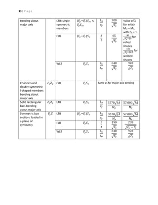
![28 | P a g e
the moment diagram between two successive braced points is not constant, the described
region is less susceptible to lateral-torsional buckling; in general, 1.0 ≤ Cb ≤ 2.3.
DESIGN FLEXURAL STRENGTH: 𝐂 𝐛 ≥ 𝟏. 𝟎, 𝐋 𝐛 ≤ 𝐋 𝐫
Incorporating C6 requires modification of Eqs. [5.8] and [5.9]. Equation [5.7] does not change.
𝑀 𝑛𝑥 = 𝑀 𝑝𝑥 = 𝑍 𝑥 𝐹𝑦 (5.7)
for bending about the major axis if. Lb ≤ Lm. However,
𝑀 𝑛𝑥 = 𝐶 𝑏 𝑀𝑟 = 𝐶 𝑏 𝑆 𝑥 (𝐹𝑦 − 𝐹𝑟) ≤ 𝑀 𝑝𝑥 (5.11)
for bending about the major axis if Lb = Lm, and the linear interpolation equation, Eq. [5.9],
becomes: 𝑀 𝑛 = 𝐶 𝑏 [ 𝑀 𝑝 – ( 𝑀 𝑝 − 𝑀𝑟)
𝐿 𝑏−𝐿 𝑝
𝐿 𝑟−𝐿 𝑝
] ≤ 𝑀 𝑝. [F1-3]
for Lm < Lb < Lr. ,. All the terms in the equations are as defined above. The relationships are
shown graphically in Fig. 5-6, where it can be seen that Lm is the unbraced length at which Eqs.
[5.7] and (F 1-3) intersect.
The design of steel beams (1.0 < Cb ≤ 2.3) should be done graphically by developing a plot
similar to that in Fig. 5-6. After determining Cb with Eq. [5.10], one can find the other required
parameters (Lp, øbMp, Lr, and øbMr) in the Load Factor Design Selection Table in Part 3 of the
AISC LRFD Manual.
When Cb > 1.0, there is a twofold advantage in including Cb > 1.0 in Eqs. [5.11] and (F1-3), and
not conservatively letting Cb = 1.0 (as in the graphs in Part 3 of the AISC LRFD Manual): (1) the
unbraced length for which Mn = Mp is extended from Lp to Lm, and (2) for Lb >Lm, the moment
capacity Mn is multiplied by Cb. The reader can find these facts depicted in Fig. 5-6.](https://image.slidesharecdn.com/steelstructuresce329-190731023301/85/Steel-structures-ce329-28-320.jpg)
![30 | P a g e
selection of rolled beams, shear strength may occasionally govern, particularly for short-span
members or those supporting concentrated loads. In built-up members, the thickness of the
web plate is often determined by shear.
For rolled shapes and built-up members without web stiffeners, the equations in Sec. F2 of the
AISC LRFD Specification can be somewhat simplified, as follows. The design shear strength is
øvVn, where øv = 0.90.
For
ℎ
𝑡 𝑤
≤
418
√ 𝐹𝑦
⇒ 𝑉𝑛 = 0.6 𝐹𝑦 𝐴 𝑤 [5.12]
For
418
√ 𝐹𝑦
<
ℎ
𝑡 𝑤
≤
523
√ 𝐹𝑦
⇒ 𝑉𝑛 = 0.6 𝐹𝑦 𝐴 𝑤
418/√ 𝐹𝑦
ℎ/𝑡 𝑤
[5.13]
Fig. 5-7 Definition of h for various shapes.
For
ℎ
𝑡 𝑤
>
523
√ 𝐹𝑦
, ⇒ 𝑉𝑛 = 𝐴 𝑤
132,000
(ℎ/𝑡 𝑤)2
[5.14]
Where: Vn = nominal shear strength, kips, Aw = area of the web, in2 = dtw
d = overall depth, in, tw = thickness of web, in, h = the following web dimensions, in: clear
distance between fillets, for rolled shapes; clear distance between flanges for welded sections
(See Fig. 5-7.)
The limit states for shear strength are yielding of the web in Eq. [5.12], inelastic buckling of the
web in Eq. [5.13], and elastic buckling of the web in Eq. [5.14].
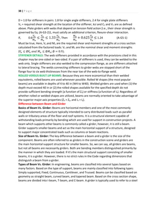
DISPLACEMENT AND VIBRATION
The two primary serviceability considerations for beams are displacement and vibration.
Traditionally, the maximum deflections of floor beams have been limited to
1
360
of the span
under the service live load specified in the governing building code. Depending on the use of
the member and its span, other deflection criteria (stated in inches or in fractions of the span)
may be more appropriate. Formulas for maximum beam deflections under various loading](https://image.slidesharecdn.com/steelstructuresce329-190731023301/85/Steel-structures-ce329-30-320.jpg)
![32 | P a g e
V = P
∆ =
𝑃𝑙3
3𝐸𝐼
Fixed end
Free end
Beams that are otherwise satisfactory have occasionally been the cause of annoying floor
vibrations. Particularly sensitive are large open floor areas with long-span beams, free of
partitions and other significant sources of damping, or energy release. To prevent excessive
vibration it has been customary to specify the minimum depth of floor beams as a fraction (e.g.,
1
20
) of their span.
DESIGN OF NON-COMPACT BEAMS AND GIRDERS (FLEXURAL DESIGN AND SHEAR DESIGN)
NON-COMPACT BEAMS
The flexural design strength is øbMn, where øb = 0.90. For non-compact beams, the nominal
flexural strength Mn is the lowest value determined from the limit states of: lateral-torsional
buckling (LTB), flange local buckling (FLB), web local buckling (WLB).
For λp < λ ≤ λr, Mn in each limit state is obtained by linear interpolation between Mn and Mn, as
follows. For the limit state of lateral-torsional buckling,
𝑀 𝑛 = 𝐶 𝑏 [ 𝑀 𝑝 – ( 𝑀 𝑝 − 𝑀𝑟)
𝜆−𝜆 𝑝
𝜆 𝑟−𝜆 𝑝
] ≤ 𝑀 𝑝. [A-F1-2]
For the limit states of flange and web buckling
𝑀 𝑛 = 𝑀 𝑝 – ( 𝑀 𝑝 − 𝑀𝑟) (
𝜆−𝜆 𝑝
𝜆 𝑟−𝜆 𝑝
) [A-F1-3]
For all limit states, if λ ≤ λp, Mn = Mp Expressions for Mp as well as for Mr, λ, λp and λr, in
each limit state, are given in Table 6-1 (which is an abridged version of Table A-F1.1 in APP. F
of the AISC LRFD Specification).
As shown schematically in Fig. 6-1, the flexural design of non-compact beams can be
accomplished by
Looking up in Table 6-1 values for Mp and Mr, λp and λr for each of the relevant limit states.
Graphically interpolating in each case to obtain an Mn for the given λ.
Selecting the minimum Mn as the nominal flexural strength
Table 6-1 Flexural Strength Parameters
Cross Sections 𝑴 𝒑 Limit State 𝑴 𝒓 λ 𝛌 𝒑 𝛌 𝒓
Channels & doubly
& singly symmetric
I-shaped beams
𝐹𝑦 𝑍 𝑥 LTB: doubly
symmetnc
members and
channels
(𝐹𝑦−𝐹𝑟)𝑆 𝑥 𝐿 𝑏
𝑟𝑦
300
√ 𝐹𝑦
See Eqs.
(F1-6), (F1-
8),& (Fl-9)](https://image.slidesharecdn.com/steelstructuresce329-190731023301/85/Steel-structures-ce329-32-320.jpg)
![34 | P a g e
Fig. 6-1 Nominal flexural strength of a non-compact beam (example)
Shear capacity should also be checked. The design shear strength is
øvVn, where øv = 0.90 and Vn, the nominal shear strength, is determined from Eq. [5. 12], [5.13],
or [5.14].
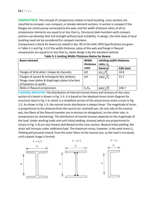
The definitions of the terms used above are
λ = slenderness parameter = minor axis slenderness ratio Lb/ry, for LTB = flange width thickness
ratio b/t, defined in Fig. 5-2, for FLB = web depth-thickness ratio hc/tw, defined in Fig. 5-2, for
WLB, λp = the largest value of λ for which Mn = Mp. λr = largest value of λ for which buckling is
inelastic, Mn = nominal flexural strength, kip-in, Mp = plastic moment, kip-in, Mr = buckling
moment at λ = λr, kip-in, Cb = bending factor, as defined in Eq. [5.10], Vn = nominal shear
strength, kips.
Additional terms used in Table 6-1 are Fy = specified minimum yield stress, ksi, Zx = plastic
section modulus about the major axis, in3, Zy = plastic section modulus about the minor axis, in3
Sx = elastic section modulus about the major axis, in3
Sxc = Sx with respect to the outside fiber of the compression flange, in3
Sxt = Sx with respect to the outside fiber of the tension flange, in3, Sy = elastic section modulus
about the minor axis, in3, Lb = laterally unbraced length, in
ry = radius of gyration about the minor axis, in
b, t, hc, tw = dimensions of cross section, defined in Fig. 5-2, in
A = cross-sectional area, in2
J = torsional constant, in4, Fr = compressive residual stress in the flange = 10 ksi for rolled
shapes = 16.5 ksi for welded shapes](https://image.slidesharecdn.com/steelstructuresce329-190731023301/85/Steel-structures-ce329-34-320.jpg)
![35 | P a g e
PLATE GIRDERS: In the AISC LRFD Specification, two terms are used for flexural members: beam
and plate girder. The differences between them are as follows.
Beam Plate Girder
Rolled or welded shape. No web stiffeners
and web
ℎ 𝑐
𝑡 𝑤
≤
970
√ 𝐹𝑦
welded shape web stiffeners or web
ℎ 𝑐
𝑡 𝑤
>
970
√ 𝐹𝑦
, or both
Stiffeners are discussed later in this chapter. Web stiffeners are not required if web hc/tw < 260
and adequate shear strength is provided by the web in accordance with Eqs. [5.12] to [5.14].
(Please note: Two different parameters in the AISC LRFD Specification refer to the clear height
of the web: h and hc. In Sec. B5 of the LRFD Specification they are thus defined:
For webs of rolled or formed sections, h is the clear distance between flanges less the fillet or
corner radius at each flange; hc is twice the distance from the neutral axis to the inside face of
the compression flange less the fillet or corner radius.
For webs of built-up sections, h is the distance between adjacent lines of fasteners or the clear
distance between flanges when welds are used and hc is twice the distance from the neutral
axis to the nearest line of fasteners at the compression flange or the inside face of the
compression flange when welds are used.
The distinction between h and hc is shown in Fig. 6-2, where it can be seen that for doubly
symmetric cross sections, h = hc.)](https://image.slidesharecdn.com/steelstructuresce329-190731023301/85/Steel-structures-ce329-35-320.jpg)
![36 | P a g e
Fig. 6-2 Definitions of h and hc : (a) singly symmetric built-up sections; (b) doubly symmetric
built-up sections
For plate girders, the maximum permissible web slenderness h/tw depends on the spacing of
the stiffeners. If,
𝑏
𝑡
≤ 1.5,
ℎ
𝑡 𝑤
≤
2000
√ 𝐹𝑦
(A-G1-1)
𝑏
𝑡
> 1.5,
ℎ
𝑡 𝑤
≤
14,000
√ 𝐹𝑦(𝐹𝑦+𝐹𝑟)
(A-G1-1)
where a = clear distance between transverse stiffeners, in, tw = web thickness, in Fy = specified
minimum yield stress of steel, ksi, Fr = compressive residual stress in flange: 16.5 ksi for plate
girders. Plate girders are covered in App. G of the AISC LRFD Specification. The stiffening of
slender plate girder webs enables them to exhibit significant post buckling strength through
"tension field action." After the web buckles, a girder acts like a Pratt truss: the stiffeners
become vertical compression members, and the intermediate web panels act as diagonal
tension members.
DESIGN FLEXURAL STRENGTH OF PLATE GIRDERS
The design flexural strength is øbMn, where øb = 0.90. To determine the nominal flexural
strength Mn : if hc/tw ≤ 970√ 𝐹𝑦. If hc/tw > 970√ 𝐹𝑦 (i.e., the web is slender), Mn is
governed by the limit states of tension flange
yielding and compression flange buckling, as follows.
For yielding of the tension flange: 𝑀 𝑛𝑥 = 𝑆 𝑥𝑡 𝑅 𝑃𝐺 𝐹𝑦 (A-G2-1)
For buckling of the compression flange: 𝑀 𝑛𝑥 = 𝑆 𝑥𝑐 𝑅 𝑃𝐺 𝐹𝑐𝑟 (A-G2-2)
The nominal flexural strength Mn is the lower value obtained from these equations, where
𝑅 𝑃𝐺 = 1 – 0.0005 𝑎 𝑟 (
ℎ 𝑐
𝑡 𝑤
−
970
√ 𝐹 𝑐𝑟
) ≤ 1.0 (A-G2-3)
where ar = ratio of web area to compression flange area, Fcr = critical compression flange stress,
ksi, Fy = minimum specified yield stress, ksi, Sxc = elastic section modulus referred to
compression flange, in3, Sxt = elastic section modulus referred to tension flange, in3.
The critical stress Fcr in Eq. (A-G2-2) depends on the slenderness parameters λ, λp, λr, and CPG.
For λ ≤ λ 𝑝 , 𝐹𝑐𝑟 = 𝐹𝑦 (A-G2-4)
For λ 𝑝 < λ ≤ λ 𝑟 𝐹𝑐𝑟 = 𝐶 𝑏 𝐹𝑦 [1 −
1
2
(
𝜆−𝜆 𝑝
𝜆 𝑟−𝜆 𝑝
)] ≤ 𝐹𝑦 (A-G2-5)
For λ ≤ λ 𝑟 𝐹𝑐𝑟 =
𝐶 𝑃𝐺
λ2
(A-G2-6)
The slenderness parameters are determined for both the limit state of lateral-torsional buckling
and the limit state of flange local buckling; the lower value of Fcr governs.
For the limit state of lateral-torsional buckling
λ =
𝐿 𝑏
𝑟 𝑇
(A-G2-7) λ 𝑝 =
300
√ 𝐹𝑦
(A-G2-8)
λ 𝑟 =
756
√ 𝐹𝑦
(A-G2-9) C 𝑃𝐺 = 286,000C 𝑏 (A-G2-10)](https://image.slidesharecdn.com/steelstructuresce329-190731023301/85/Steel-structures-ce329-36-320.jpg)
![37 | P a g e
where Cb is determined from Eq. [5. 10] and rT is the radius of gyration of compression flange
plus one-third of the compression portion of the web taken about an axis in the plane of the
web, in. For the limit state of flange local buckling
λ =
𝑏 𝑓
2𝑡 𝑓
(A-G2-11) λ 𝑝 =
65
√ 𝐹𝑦
(A-G2-12)
λ 𝑟 =
150
√ 𝐹𝑦
(A-G2-13) C 𝑃𝐺 = 11,200 (A-G2-14) C 𝑏 = 1.
The limit state of web local buckling is not applicable.
DESIGN SHEAR STRENGTH OF PLATE GIRDERS
The design shear strength of øv Vn, where øv = 0.90.
For
ℎ
𝑡 𝑤
≤
187
√ 𝑘/𝐹𝑦
𝑉𝑛 , = 0.6 𝐴 𝑤 𝐹𝑦 (A-G3-1)
For
ℎ
𝑡 𝑤
>
187
√ 𝑘/𝐹𝑦
𝑉𝑛 , = 0.6 𝐴 𝑤 𝐹𝑦 (𝐶𝑣 +
1−𝐶 𝑣
1.15√1+(𝑎/ℎ)2
) (A-G3-2)
Except for end panels and where
𝑎
ℎ
> {
3.0
𝑜𝑟
260
(ℎ/𝑡 𝑤)2
[6.1]
In such cases tension field action does not occur and: 𝑉𝑛 , = 0.6 𝐴 𝑤 𝐹𝑦 𝐶𝑣 (A-G3-3)
In the preceding equations: k = 5 +
5
(𝑎/ℎ)2
(A-G3-4)
Except that k = 5.0 if Expression [6.1] is true or if no stiffness are present: Aw is the area of the
web, in2 = dtw; and d is the overall depth, in.
If, 187√
𝑘
𝐹𝑦
≤
𝑘
𝑡 𝑤
≤ 234√
𝑘
𝐹𝑦
, 𝐶𝑣 =
187√ 𝑘/𝐹𝑦
ℎ/𝑡 𝑤
(A-G3-5)
If,
ℎ
𝑡 𝑤
> 234√
𝑘
𝐹𝑦
, 𝐶𝑣 =
44,000 𝑘
(ℎ/𝑡 𝑤)2 𝐹𝑦
(A-G3-6)
WEB STIFFENERS: Transverse stiffeners are required if web h/tw ≥ 260 or web shear strength,
(for unstiffened beams), is inadequate. The stiffeners should be spaced to provide sufficient
shear strength in accordance with the preceding provisions for plate girders.
Additional requirements for stiffeners are: 𝐼𝑠𝑡 ≥ 𝑎𝑡 𝑤
3
𝑗 [6.2]
Whenever stiffeners are required and:
𝐴 𝑠𝑡 ≥
𝐹𝑦
𝐹𝑦.𝑠𝑡
[0.15Dℎ𝑡 𝑤(1 − 𝐶𝑣)
𝑉𝑢
∅ 𝑣 𝑉𝑛
− 18𝑡 𝑤
2
] ≥ 0 (A-G4-2)
For tension field action where: J =
2.5
(𝑎/ℎ)2
– 2 ≥ 0.5. (A-G4-1)
and Ist = moment of inertia of a transverse web stiffener about an axis in the web center for
stiffener pairs or about the face in contact with the web plate for single stiffeners, in4.
Ast = cross-sectional area of a transverse web stiffeners, in2. Fy = specified minimum yield stress
of the girder steel, ksi. Fy.st = specified minimum yield stress of the stiffener material, ksi](https://image.slidesharecdn.com/steelstructuresce329-190731023301/85/Steel-structures-ce329-37-320.jpg)
![43 | P a g e
From Eq. [4.1], G’A = 1.18/0.84 = 1.41.
𝑃 𝑢
𝐴 𝑔
=
200 𝑘𝑖𝑝𝑠
9.71 𝑖𝑛2
= 20.6 ksi.
Fig. 4.5
From Table 4-3, by interpolation, SRF = 0.72. At joint A, GA = G’A x SRF = 1.41 x 0.72 = 1.02.
(a) For rigid attachment to the foundation, GB = 1.0. K = 1.3 in Fig. 4-2.
(b) For pin connection to the foundation, GB = 10. Drawing a line in Fig. 4-2 from GA = 1.02
GB = 10 indicates that K = 1.9.
4.12. Determine the design strength of a W8 x 40 column (A36 steel).
𝐾𝑥 𝐿 𝑥 = 𝐾 𝑦 𝐿 𝑦 = 15.0 ft.
For a W8 x 40 section, A = 17.7 in2, 𝑟𝑥 = 3.53 in, 𝑟𝑦 = 2.04 in. Since 𝑟𝑦 < 𝑟𝑥, 𝐾 𝑦 𝑙 𝑦/𝑟𝑦 governs.
𝐾 𝑦 𝐿 𝑦
𝑟 𝑦
=
15 𝑓𝑡 ×12 𝑖𝑛/𝑓𝑡
2.04 𝑖𝑛
= 88.2.
From Table 4-4, ∅ 𝑐 𝐹𝑐𝑟 = 20.32 ksi. The design strength of the column
∅ 𝑐 𝑃𝑛 = 𝛿 𝑐 𝐹 𝑐𝑟 𝐴 𝑔 = 20.32 kips/in2 x 11.7 in2 = 238 kips.
In probs. 5.1 to 5.2, determine whether the given beam is compact: (a) in A36 steel (Fy = 36 ksi),
(b) if Fy = 50 ksi.
5.1. W6 x 15. If the width-thickness ratio of an element is greater than λp, the section is non-
compact. For the flanges of a W shape.
λ 𝑝 =
65
√ 𝐹𝑦
= {
65
√36
= 10.8 𝑖𝑓 𝐹𝑦 = 36 𝑘𝑠𝑖
65
√50
= 9.2 𝑖𝑓 𝐹𝑦 = 50 𝑘𝑠𝑖
For the web of a W shape
λ 𝑝 =
640
√ 𝐹𝑦
= {
640
√36
= 106.7 𝑖𝑓 𝐹𝑦 = 36 𝑘𝑠𝑖
640
√50
= 90.5 𝑖𝑓 𝐹𝑦 = 50 𝑘𝑠𝑖](https://image.slidesharecdn.com/steelstructuresce329-190731023301/85/Steel-structures-ce329-43-320.jpg)
![44 | P a g e
From the Properties Tables for W Shapes, in Part 1 of the AISC LRFD Manual (Compact Section
Criteria): for a W6 x 15: flange
𝑏
𝑡
=
𝑏 𝑓
2 𝑡𝑓
= 11.5, web
ℎ 𝑐
𝑡 𝑤
= 21.16.
Since flange (b/t = 11.5) > (λp = 10.8), the W6 x 15 beam is non-compact in A36 steel. Likewise,
it is non-compact if Fy = 59 ksi.
5.2. W12 x 65. From the Properties Tables for W Shapes, for a W12 x 65.
flange
𝑏
𝑡
=
𝑏 𝑓
2 𝑡𝑓
= 9.9, web
ℎ 𝑐
𝑡 𝑤
= 24.9.
(a) In A36 steel: flange 𝜆 𝑝= 10.8, web 𝜆 𝑝 = 106.7. (See prob. 5.1)
Since flange (b/t = 9.9) < (λp = 10.8), and web (hc/tw =24.9) < (λp = 106.7), a W12 x 65 beam
compact in A36 steel.
(D) However, if Fy = 50 ksi. flange 𝜆 𝑝= 9.2, web 𝜆 𝑝 = 90.5. (See prob. 5.1)
Because flange (b/t = 9.9) > (λp = 9.2), a W12 x 65 beam is non-compact if Fy = 50 ksi.
5.7. For the same W24 x 76 beam in major-axis bending, laterally braced at its centerline,
with either a uniform load or a concentrated load at the center, determine the flexural design
strength.
𝐶 𝑏 = [1.75 + 1.05
𝑀1
𝑀2
+ 0.3 (
𝑀1
𝑀2
)
2
] ≤ 2.3
According to Eq. [5-10]:
For either unbraced half of the beam under either loading indicated, M1 = 0 and
M2 > 0; M1/M2 = 0. In Eq. [5-10], Cb = (1.75 + 1.05 x 0 + 0.3 x 0) = 1.75.
For all Lb, the design flexural strength for 𝐶 𝑏 = 1.75, ∅ 𝑏 𝑀 𝑛𝑥( 𝐶 𝑏 = 1.75) = 1.75 x ∅ 𝑏 𝑀 𝑛𝑥( 𝐶 𝑏 =
1.0) ≤ ∅ 𝑏 𝑀 𝑝𝑥. The previous ( 𝐶 𝑏 = 1.0) design flexural strengths are multiplied by ( 𝐶 𝑏 = 1.75);
however, the plastic moment strength (∅ 𝑏 𝑀 𝑝𝑥 = 540kip-ft) cannot be exceeded.
5.8. Select the most economical rolled shape for a27-ft simply supported floor beam. The
upper (compression) flange of the beam is adequately welded to the floor deck at 1 ft 0 in
intervals. Dead load supported by the beam (including its own weight) is 1.3 kips per linear
foot; live load is 2.6 kips per linear foot. Steel is A36. Assume:
(a) There is no member depth limitation. (b) The deepest (architecturally allowable) member is
a W21. (c) The deepest desired member is a W18.
For the case of dead load and floor live load only, the critical load combination formula is
(A4-2): 1.2D + 1.6L + 0.5(Lr or S or R) = 1.2 x 1.3 kips/ft + 1.6 x 2.6 kips/ft + 0 = 5.7 kips/ft
For uniformly distributed loads, maximum M = wl2 / 18 and V = wl2.
Required 𝑀 𝑢 =
5.7 𝑘𝑖𝑝𝑠/𝑓𝑡 ×(27𝑓𝑡)2
8
= 521 kip-ft.
Required 𝑉𝑢 = 5.7
𝑘𝑖𝑝𝑠
𝑓𝑡
×
27𝑓𝑡
2
= 77 kips.
Here, Lb = 1.0 < Lp (all rolled shapes).
(a) In Table 5-3, as in the beam Selection Table in the LRFD Manual, the most economical beams
appear in boldface print. Of those beams, the one of least weight for which ∅ 𝑏 𝑀 𝑛= ∅ 𝑏 𝑀 𝑝 ≥](https://image.slidesharecdn.com/steelstructuresce329-190731023301/85/Steel-structures-ce329-44-320.jpg)
![45 | P a g e
521 kip-ft. is a W24 x 76.
Checking shear strength with Eq. [5.12], for
ℎ
𝑡 𝑤
≤ (418/√ 𝐹𝑦 = 418/√36 =) 69.7.
𝑉𝑛 = 0.6𝐹𝑦 𝐴 𝑤 = 0.6 x 36 ksi x 𝑑𝑡 𝑤
∅ 𝑣 𝑉𝑛 = 0.90 x 9.6 x 36 ksi 𝑑𝑡 𝑤 = 19.4 ksi x 𝑑𝑡 𝑤
For a W24 x 76,
ℎ
𝑡 𝑤
= 49.0 < 69.7. (See Properties Tables for W Shapes in the AISC LRFD Manual,
part 1.) Then ∅ 𝑣 𝑉𝑛 = 19.4 ksi x 23.92 in x 0.440 in = 205 kips > 77 kips required. Use a W24 x 76.
(b) By inspection of Table 5-3, the least-weight W21 for which ∅ 𝑏 𝑀 𝑛𝑥 = ∅ 𝑏 𝑀 𝑝𝑥 ≥ 521
kip/ft is a W21 x 83. Checking shear: ∅ 𝑣 𝑉𝑛 = 19.4 ksi x 𝑑𝑡 𝑤.. For a W21 x 83, ∅ 𝑣 𝑉𝑛 = 19.4 ksi x
21.43 in x 0.515 in = 214 kips > 77 kips required. Use a W21 x 83.
(c) By inspection of Table 5-3, the least-weight W18 for which Q6M* : ∅ 𝑣 𝑉𝑛= 521 kip-ft. is a
W18 x 97. Checking shear: ∅ 𝑣 𝑉𝑛= 19.4 ksi x 𝑑𝑡 𝑤. For a W18 x 97, ∅ 𝑣 𝑉𝑛 = 19.4 ksi x 18.59 in x
0.535 in = 193 kips > 77 kips required. Use a W18 x 97.
(Note: In lieu of calculations, the design shear strengths ∅ 𝑣 𝑉𝑛 for W shapes can be found
tabulated in the section Uniform Load Constants in Part 3 of the AISC LRFD Manual.)
5.14. Simply supported 30-ft-long floor beams, W18 x 35, are spaced 10 ft. 0 in center-to-
center. What is their maximum deflection under a live load of 50lb/ft2?
Sol: w = 50
𝑙𝑏
𝑓𝑡2
x 10 ft. = 500
𝑙𝑏
𝑓𝑡
= 0.5
𝑘𝑖𝑝𝑠
𝑓𝑡
. For a W18 x 35 beam, 𝐼𝑥 = 510 in. From Table 5-2, for
a uniformly loaded simply supported beam, the maximum deflection.
∆=
5𝑤𝑙2
384𝐸𝐼
=
5×0.5
𝑘𝑖𝑝𝑠
𝑓𝑡
×(30𝑓𝑡)4
384×29,000
𝑘𝑖𝑝𝑠
𝑖𝑛2 ×510𝑖𝑛2
× (12 𝑖𝑛/𝑓𝑡)3
= 0.62 in.
∆= 0.62𝑖𝑛 <
𝐿
360
=
30 𝑓𝑡 ×12𝑖𝑛/𝑓𝑡
360
= 1.0 in.
Since live load Deflection: It should generally be acceptable.
5.15. Determine the maximum deflections of the same W18x35 beams under concentrated
loads of 7.5 kips at mid-span. From Table 5-2, for a concentrated load on a simply supported
beam at mid-span; the maximum deflection
∆=
𝑝𝑙3
48𝐸𝐼
=
7.5 𝑘𝑖𝑝𝑠 ×(30𝑓𝑡)3×(12 𝑖𝑛𝑓𝑡)3
48 × 29,000
𝑘𝑖𝑝𝑠
𝑖𝑛2 × 510𝑖𝑛2
= 0.49 in.
6.6. Determine the minimum web thickness for the plate girder in Fig. 6-3, both with and
without web stiffeners; assume, A36 steel. According to the AISC LRFD Specification (App. G),
in unstiffened girders h/tw must be less than 260.
ℎ
𝑡 𝑤
< 260 implies that 𝑡 𝑤 >
ℎ
260
=
56 𝑖𝑛
260
= 0.22 in.
In stiffened girders (a/h ≤ 1.5):
ℎ
𝑡 𝑤
≤
2000
√ 𝐹𝑦
=
2000
√36
= 333
In stiffened girders (a/h > 1.5):
ℎ
𝑡 𝑤
≤
14,000
√ 𝐹𝑦(𝐹𝑦 + 16.5)
=
14,000
√36(36 + 16.5)
= 322](https://image.slidesharecdn.com/steelstructuresce329-190731023301/85/Steel-structures-ce329-45-320.jpg)
![47 | P a g e
From Eq. (H1-2), 𝑀 𝑢𝑥 = 𝐵2 𝑀𝑙𝑡𝑥 , where [according to Eq. (H1-5)]
𝐵2 =
1
1−
∑ 𝑃 𝑢
∑ 𝐻
(
∆ 𝑜ℎ
𝐿
)
=
1
1−
4800 𝑘𝑖𝑝𝑠
80 𝑘𝑖𝑝𝑠(0.0025)
= 1.18.
The second-order required flexural strength Mux = 1.18 x 100 kip-ft = 118 kip-ft. Selecting a trial
W12 shape with Eq. [8.2], we obtain: 𝑃𝑢.𝑒𝑓𝑓 = 𝑃𝑢 + 𝑃𝑢𝑥 𝑚 + 𝑀 𝑢𝑦 𝑚𝑈.
Where for a W12 (KL = 14.4 ft), m = 2.4 and U = 1.5. 𝑃 𝑢. 𝑒𝑓𝑓 = 400 + 118 x 2.4 + 0 = 683 kips.
By interpolation in the Column Load Tables of the AISC LRFD Manual (p. 2-24), if Fy = A36 ksi
and KL = 14.4 ft. ∅ 𝑐 𝑃𝑛 = 732 kips (> 𝑃 𝑢. 𝑒𝑓𝑓 = 43 kips) for a W12 x 96.
Selecting the appropriate beam-column interaction formula, (H1-1a) or (H1-1b), we obtain:
𝑃𝑢
∅ 𝑐 𝑃𝑛
=
400 𝑘𝑖𝑝 − 𝑓𝑡
732 𝑘𝑖𝑝 − 𝑓𝑡
= 0.55 > 0.2
Use formula (H1-1a), which, for 𝑀 𝑢𝑦 = 0, reduces to
𝑃𝑢
∅ 𝑐 𝑃𝑛
+
8
9
𝑀 𝑢𝑥
∅ 𝑏 𝑀 𝑛𝑥
≤ 1.0
The design flexural strength ∅ 𝑏 𝑀 𝑛𝑥 for a W12 x 96 can be determined from the Beam
Selection Table on page 3-15 of the AISC LRFD Manual: because (Lb = 12 ft.) < (Lp = 12.9 ft.),
∅ 𝑏 𝑀 𝑛𝑥 = ∅ 𝑏 𝑀 𝑝 = 397 kip-ft. as tabulated. Substituting in the interaction formula:
0.55 +
8
7
×
118 𝑘𝑖𝑝−𝑓𝑡
397 𝑘𝑖𝑝−𝑓𝑡
≤ 1.0 = 0.55 + 0.26 = 0.81 < 1.0.
By a similar solution of interaction formula (H1-1a), it can be shown that a Wl2 x 87 and a
W12 x 79 are also adequate.
10.5. A W18 x 40 interior beam is shown in Fig. 10-5. Steel is A36, beam span is 30 ft. 0 in, and
beam spacing is 10 ft. 0 in. The beams are to act compositely with a 5-in normal-weight
concrete slab; f’c = 5.0 ksi.
Fig. 10-5
(a) For an interior beam, the effective slab width on either side of the beam centerline is the
minimum of
𝐿
8
=
30.0 𝑓𝑡
8
= 3.75 ft = 45 in.
𝑠
2
=
10.0 𝑓𝑡
2
= 5 ft. The effective slab width is 2 x 45 in = 90 in.
(b) In positive moment regions, Vh for full composite action is the smaller of](https://image.slidesharecdn.com/steelstructuresce329-190731023301/85/Steel-structures-ce329-47-320.jpg)
![48 | P a g e
0.85f’c Ac = 0.85 x 5 ksi x (90 in x 5 in) = 1913 kips. AsFy = 11.8 in2 x 36 ksi = 425 kips
Vh = 425 kips. (c) The nominal strength of a single shear stud [from Eq. (15-1)] is
𝑄 𝑛 = 0.5𝐴 𝑠𝑐√𝑓′ 𝑐 𝐸𝑐 ≤ 𝐴 𝑠𝑐 𝐹𝑢 , For a
3
4
− 𝑖𝑛 − 𝑑𝑖𝑎𝑚𝑒𝑡𝑒𝑟 𝑠𝑡𝑢𝑑,
𝐴 𝑠𝑐 = 𝜋 (
0.75 𝑖𝑛
2
)
2
= 0.44 in2, 𝐸𝑐 = 𝑤1.5
√𝑓′ 𝑐 = 1451.5
√5.0 = 3904 ksi, Fu = 60 ksi.
𝑄 𝑛 = 0.5 × 0.44𝑖𝑛2
√5.0 𝑘𝑠𝑖 × 3904 𝑘𝑠𝑖 ≤ 0.44 𝑖𝑛2
× 60 𝑘𝑠𝑖 = 30.9 kips ≤ 26.4
kips. = 26.5 kips per stud. For the beam shown in Fig. 10-6, the required number of shear
studs is 2n = 2 x 17 = 34.
Fig. 10-6
Assuming a single line of shear studs (over the beam web), stud spacing=30.0 ft/34 = 0.88ft =
10.6 in. This is greater than the six-stud diameter (or 6 x
3
4
in = 4.5in) minimum spacing, and less
than the eight slab thickness (or 8 x 5 in : 40 in) maximum spacing, which is satisfactory.
10.7. Assume the beams in Fig. 10-5 are cantilever beams: A36 steel, with a cantilever span of
8 ft 0 in. Slab reinforcement is No.4 bars (Ar = 0.20 in2 per bar) at 1 ft 0 in center-to-center. Bars
are Grade 60 steel. (a) For an interior beam, the effective slab width on either side of the beam
centerline is the minimum of
L
8
=
8.0 ft
8
= 1.0 ft. .
𝑠
2
=
10.0 𝑓𝑡
2
= 5 ft.
The effective slab width is 2 x 1.0 ft = 2.0 ft.
(b) In negative-moment regions (such as cantilevers): Vh = ArFyr for full composite action, where
Ar and Fyr are the cross-sectional area and minimum yield stress of the reinforcement,
respectively. Because the slab is in tension, the concrete cannot participate in composite
action. For an effective slab width of 2.0 ft.
𝐴 𝑟 =
0.20 𝑖𝑛2
𝑏𝑎𝑟
×
1 𝑏𝑎𝑟
𝑓𝑡
x 2.0 ft. width = 0.40 in2. 𝑉ℎ = 0.40 in2 x 60 ksi = 24 kips.
(c) The nominal strength of a single shear stud is Qn = 26.4 kips. Although n = Vh/Qn =
24kips / 26.4 kips per stud = 0.9 would indicate that one stud is satisfactory, the actual number
of shear studs is governed by the maximum spacing of eight times the slab thickness:
𝑛 =
𝑠𝑝𝑎𝑛
𝑚𝑎𝑥𝑖𝑚𝑢𝑚 𝑠𝑝𝑎𝑛
=
8.0 𝑓𝑡 𝑋 12 𝑖𝑛/𝑓𝑡
8 𝑋 5 𝑖𝑛
= 2.4 or 3 shear studs.
11.7. Determine the design tensile strength of a
7
8
in-diameter bolt if it is (a) A325, (b) A490,
(c) A307. The nominal cross-sectional area of a
7
8
-in-diameter bolt is](https://image.slidesharecdn.com/steelstructuresce329-190731023301/85/Steel-structures-ce329-48-320.jpg)
![49 | P a g e
𝐴 = 𝜋 (
𝐷
2
)
2
= 𝜋 (
7
8
𝑖𝑛
2
)
2
= 0.60 in2
.
The design tensile strength of a bolt: ∅𝑃𝑛 = ∅𝐹𝑡𝑛 𝐴
Where ø = 0.75 and 𝐹𝑡𝑛 is as listed in Table 11.5.
(a) For a
7
8
-in-diameter A325 bolt, the design tensile strength
∅𝑃𝑛 = 0.75 x 90
𝑘𝑖𝑝𝑠
𝑖𝑛2
x 0.60 in2 = 40.6 kips.
(b) For a
7
8
-in-diameter A490 bolt, the design tensile strength
∅𝑃𝑛 = 0.75 x 112.5
𝑘𝑖𝑝𝑠
𝑖𝑛2
x 0.60 in2 = 50.7 kips.
(c) For a
7
8
-in-diameter A307 bolt, the design tensile
∅𝑃𝑛 = 0.75 x 45.0
𝑘𝑖𝑝𝑠
𝑖𝑛2
x 0.60 in2 = 20.3 kips.
11.14. Design a base plate for a W14 x 90 column with a factored axial load of 700 kips. All
steel is A36. The base plate is on a footing 2 ft 0 in x 2 ft 0 in; f’c = 4 ksi.
The design bearing strength for steel bearing on concrete is determined from Eq. (11.5) or
(11.6); the former for bearing on the full area of concrete, and the latter for bearing on less
than the full area. The dimensions of the W14 x 90 column d bf = 14.02 in x 14.52 in. Try a 16 in
x 16 in base plate and use Eq. (11.7).
𝐴2 = 24 in x 24 in = 576 in2. 𝐴1 = 16 in x 16 in = 256 in2
𝑓′ 𝑐 = 4
𝑘𝑖𝑝𝑠
𝑖𝑛2
, ø = 0.60. The design bearing strength: ∅𝑐 𝑃 𝑝 = 0.85𝑓′ 𝑐
𝐴1√
𝐴1
𝐴2
= 0.85 x 4
𝑘𝑖𝑝𝑠
𝑖𝑛2
x 256 in2 x √
576 𝑖𝑛2
256 𝑖𝑛2
= 1306 kips > 700 kips required.
N = 16.0 in, d = 14.0 in, m = 0.5(N – 0.95 d) = 0.5(16 in – 0.95 x 14 in) = 1.35 in.
B = 16.0 in, bf = 14.52 in, n = 0.5(B – 0.80 bf) = 0.5(16 in – 0.80 x 14.52 in) = 2.19 in.
To determine c, solve Eqs. [11.8] to [11.10].
𝑃𝑜 =
𝑃 𝑢
𝐵𝑁
𝑏𝑓 𝑑 =
700 𝑘𝑖𝑝𝑠
16 𝑖𝑛 ×16 𝑖𝑛
x 14.02 in x 1.52 in = 556 kips.
𝐴 𝐻 =
𝑃𝑜
0.6(0.85√ 𝐴2/𝑏𝑓 𝑑𝑓′ 𝑐)
≥
𝑃𝑜
0.6(1.7𝑓′
𝑐
)
=
556 𝑘𝑖𝑝𝑠
0.6(0.85
√
576𝑖𝑛2
(14.52 𝑖𝑛 × 14.0 𝑖𝑛)4
𝑘𝑖𝑝𝑠
𝑖𝑛2
≥
556 𝑘𝑖𝑝𝑠
0.6 × (1.7 × 4
𝑘𝑖𝑝𝑠
𝑖𝑛2 )
= 162 𝑖𝑛2
≥ 136𝑖𝑛2
= 162𝑖𝑛2](https://image.slidesharecdn.com/steelstructuresce329-190731023301/85/Steel-structures-ce329-49-320.jpg)
![50 | P a g e
C =
1
4
[(𝑑 + 𝑏𝑓 + 𝑡𝑓) − √(𝑑 + 𝑏𝑓 + 𝑡𝑓) − 4(𝐴 𝐻 + 𝑡𝑓 𝑏𝑓)]
(𝑑 + 𝑏𝑓 + 𝑡𝑓) = (14.02 + 14.52 – 0.71) in = 27.83 in.
C =
1
4
[27.83 𝑖𝑛 − √(27.83 𝑖𝑛)2 − 4(162 𝑖𝑛2 − 0.71 𝑖𝑛 × 14.52))] c = 4.26 in.
Referring to Eq. [11.8]: m = 1.35 in, n = 2.19 in c = 4.26 in
√
2𝑃𝑢
0.92𝐹𝑦 𝐴 𝐻
= √
2 × 700 𝑘𝑖𝑝𝑠
0.9 × 3 𝑘𝑖𝑝𝑠/𝑖𝑛2 × 16 𝑖𝑛 × 16 𝑖𝑛
= 0.41
√
2𝑃𝑜
0.92𝐹𝑦 𝐴 𝐻
= √
2 × 556 𝑘𝑖𝑝𝑠
0.9 × 3 𝑘𝑖𝑝𝑠/𝑖𝑛2 × 162 𝑖𝑛2
= 0.46
Base plate thickness tp is the largest of (1.35 in x 0.41 = 0.55 in), (2.I9 in x 0.41 = 0.90 in), and
(4.26 in x 0.46 = 1.96 in). Use a base plate 16 in x 2 in x 16 in.
12.4. Determine the maximum load that can be hung from a plate (12 in long x 7 in wide)
welded to the bottom flange of a W18 x 50 beam. All steel is A36.
For a concentrated tensile force acting on the bottom flange of a beam, the applicable limit
states are (1) local web yielding and (5) local flange bending. The corresponding equations are
(K1-2) and (K1-1). In solving Eq. (K1-2) for a W18 x 50 with a 12-in load bearing (in Prob. 12.3) it
was determined that Pu = 233 kips. Because the width of plate = 7 in > 0.15bf (= 0.15 x 7.495 in =
1.12 in), Eq. (K1-1) must be checked:
𝑃𝑢 ≤ ∅𝑅 𝑛 = 0.90 x 6.25 𝑡𝑓
2
𝐹𝑦 = 0.90 x 6.25(0.570 in)2 x 36 ksi. 𝑃𝑢 ≤ 66 kips.
The maximum (factored) hanging load is 66 kips, based on the limit state of local flange
bending. If stiffeners are provided or if the hanging load is confined to the central
0.15bf (= 1.12 in) of the beam flange, 233 kips can be hung.
What are the merits and demerits of welded connections?
Merits: 1) Due to the absence of gusset plates, connecting angles etc. Welded structures are
lighter. 2) The absence of making holes for fasteners, making welding process quicker. 3)
Welding is more adaptable than bolting or riveting. For example, even circular tubes can be
easily connected by welding.
Demerits: 1) Due to uneven heating and cooling members are likely to distort in the
process of welding. 2) There is a greater possibility of brittle fracture in welding. 3) A welded
joint fails earlier than bolted joint, if the structure is under fatigue stresses.
Example: Design a suitable fillet welded joint between two plates of size 160 mm x 8 mm, and
200 mm x 8 mm to developed the full strength of the smaller plate in tension. Assume
permissible tensile stress in plate = 1500 kg/cm2.](https://image.slidesharecdn.com/steelstructuresce329-190731023301/85/Steel-structures-ce329-50-320.jpg)
![56 | P a g e
Sol: Size of weld = 6 mm
Effective throat thickness = 0.7 x 6 = 4.2 mm
Effective length of fillet weld
= 200 + 200 + 200 = 600 mm
Strength of fillet weld
= (4.2 x 600 x 110/1000) = 277.2 KN.
Example 7.3. In Example 7.2, the pull to be transmitted by the tie is 300 KN. Determine the
necessary overlap of the tie.
Solution: Size of weld = 6 mm
Effective throat thickness = 4.2 mm
Pull transmitted by the end fillet weld = (4.2 x 200 x 110/1000) = 92.4 kN
Let l be the necessary overlap required, the pull transmitted by the side fillet is
= (4.2 x 2 x l x 110/1000) = 0.924 l KN.
Total pull transmitted = 92.4 + 0.924 l = 300 KN.
Therefore, the necessary overlap of the tie l = 224.7 mm.
Example 7.4. The web plate of a built-up welded I-section is 200 mm x 12 mm and the flange
plates are 100 mm x 12 mm. The size of fillet weld is 6 mm. Compute the maximum shear
force that may be allowed at any section, if the average allowable shear in the web is 0.4
fy and maximum allowable shear in the weld is 110 N/mm2.
Solution: Moment of inertia of the built-up section (about xx axis)
𝐼𝑥𝑥 = 1/12[10 x 22.43 – 8.8 x 203] x 104 = 3499.52 x 104 mm4.
Intensity of shear stress (at weld section): 𝜏 𝑠 = (
𝐹.𝐴𝑦̅
𝐼 𝑥𝑥.(2𝑡)
)
Where,
𝐴𝑦̅ = Moment of the area above the section about xx axis.
F = shear force at the section.
t = Effective throat thickness of one weld.
𝜏 𝑠 = (
𝐹×100×12×(100+6)
3499.52×104×2×0.7×6
)
= 0.11 KN/mm2. F = 254.21 KN.
The average shear stress in the web is 0.4 x 250 N/mm2.
Allowable shear force in the web:
F1 = (200 x 12 x 0.4 x 250/1000) = 240 KN.
The design drawing is Fig. 7.19.
Example 7.5. Design a suitable longitudinal fillet weld to
connect the plates as shown in Fig. 7.20 and to transmit a pull equal to the full strength of](https://image.slidesharecdn.com/steelstructuresce329-190731023301/85/Steel-structures-ce329-56-320.jpg)
![61 | P a g e
only be approximated in practice, so the discussion accompanying the alignment chart
recommends that G be taken as 10.0.
From the alignment chart with GA = 0.95 and GB = 10.0, Kx = 1.85 for column BC.
EXAMPLE: Select the lightest W-shape that can resists a factored compressive load Pu of
190 kips. The effective length is 24 feet. Use ASTM A572 Grade 50 steel.
SOL: The appropriate strategy here is to find the lightest shape for each nominal size and then
choose the lightest overall. The choices are as follows.
W4, W5 and W6: None of the tabulated shape will work.
W8: W 8 58, cPn = 205 kips. W10: W10 49, cPn = 254 kips
W12: W12 53, cPn = 261 kips. W14: W14 61, cPn = 293 kips
Note that the load capacity is not proportional to the weight (or cross-sectional area). Although
the W8 58 has the smallest design strength of the four choices, it is the second heaviest.
ANSWER: Use a W10 49.
Example: Select a W18 shape of A36 steel that can resist a factored load of 1054 kips.
The effective length KL is 26 feet.
Sol: Try Fcr = 24 ksi (two-thirds of Fy):
Required 𝐴 𝑔 =
𝑃 𝑢
∅ 𝑐 𝐹𝑐𝑟
=
1054
0.9(24)
= 48.8 in2. Try W18 x 192: 𝐴 𝑔 = 56.4 in2 > 48.8 in2.
𝐾𝐿
𝑟 𝑚𝑖𝑛
26(12)
2.79
= 111.8 < 200. (OK) ⇒ 𝐹 𝑒 =
𝜋2 𝐸
(
𝐾𝐿
𝑟
)
2 =
𝜋2×29000
(111.8)2 = 22.9 ksi.
𝐹𝑒 > 0.44 𝐹𝑦 (15.84). LFRD Eq. E.3.2.
𝐹𝑐𝑟 = [0.658
𝐹 𝑦
𝐹 𝑒 ] 𝐹𝑦 = [0.658
36
22.9] x 36 = 0.532 x 36 = 18.64 ksi.
∅ 𝑐 𝑃𝑛 = 0.9𝐴 𝑔 𝐹𝑐𝑟 = 0.9 x 56.4 x 18.64 = 943 kips < 1054k.
Try 𝐹𝑐𝑟 = 18.64 ksi ( the value just computed for the W18 x 192):
Required 𝐴 𝑔 =
𝑃 𝑢
∅ 𝑐 𝐹𝑐𝑟
=
1054
0.9(18.64)
= 62.83 in2. Try W18 x 234: 𝐴 𝑔 = 68.8 in2 > 62.83 in2.
𝐾𝐿
𝑟 𝑚𝑖𝑛
26(12)
2.85
= 109.5 < 200. (OK) ⇒ 𝐹 𝑒 =
𝜋2 𝐸
(
𝐾𝐿
𝑟
)
2 =
𝜋2×29000
(109.5)2 = 23.87 ksi.
𝐹𝑒 > 0.44 𝐹𝑦. LFRD Eq. E.3.2.
𝐹𝑐𝑟 = [0.658
𝐹 𝑦
𝐹 𝑒 ] 𝐹𝑦 = [0.658
36
23.87] x 36 = 0.532 x 36 = 19.15 ksi.
∅ 𝑐 𝑃𝑛 = 0.9𝐴 𝑔 𝐹𝑐𝑟 = 0.9 x 68.8 x 19.15 = 1185 kips < 1054k. (OK).
This shape is not in the column load tables, so the width thickness ratios must be checked.
𝑏 𝑓
2𝑡 𝑓
= 2.8 <
95
√36
= 15.8 (ok).
ℎ
𝑡 𝑤
= 13.8 <
253
√36
= 42.2 (ok). Use a W18 x 234. Ans.](https://image.slidesharecdn.com/steelstructuresce329-190731023301/85/Steel-structures-ce329-61-320.jpg)

This document provides an overview of steel structures and structural steel design methods. It begins with definitions of common structural steel elements like beams, columns, and connections. It then discusses the mechanical properties and stress-strain behavior of structural steels. Different grades of steel are described along with typical structural shapes. The document concludes with an explanation of the two primary structural steel design methods: Allowable Stress Design (ASD) and Load and Resistance Factor Design (LRFD).


![[Deck] What's New in Spark-Iceberg Integration via DSV2.pptx](https://cdn.slidesharecdn.com/ss_thumbnails/deckwhatsnewinspark-icebergintegrationviadsv2-260210005337-25955b12-thumbnail.jpg?width=640&height=640&fit=bounds)


