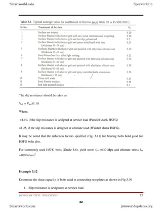
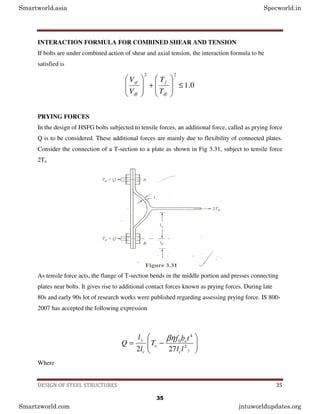
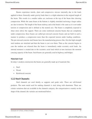
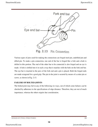
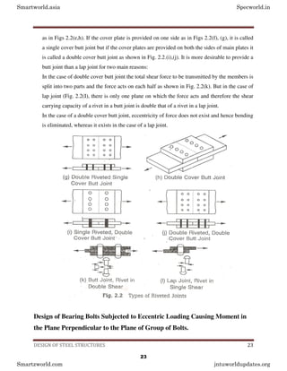
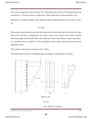
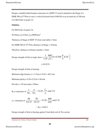
The document covers the design of steel structures, highlighting the advantages and disadvantages of steel, various types of loads, design methods including Limit State Method (LSM) and Allowable Stress Design (ASD), and types of structural steel sections such as beams, channels, angles, and flats. It emphasizes the importance of understanding structural design for construction managers to ensure safety, serviceability, and economy in projects. Additionally, it addresses bolted connections, detailing their advantages over riveted connections, while also noting challenges such as cost and vulnerability to vibrations.


![DESIGN OF STEEL STRUCTURES 26
+
=
∑
∑
i
i
y
y
h
M
2
21
2
1
1
'
Tensile force Tdh in extreme bolt can be found.
This equation gives the moment resisted by the bolts in tension from which the maximum tensile
force in the extreme bolt Tb can be calculated. Then the design required is
0
.
1
2
2
≤
+
dh
b
dh
sb
T
T
V
V
Steps to be followed in the design
Step 1: Select nominal diameter ‘d’ of bolts.
Step 2: Adopt a pitch(p) of 2.5d to 3.5d for bolts.
Step 3: Bolts are to be provided in two vertical rows. Number of bolts necessary in each row is
computed from the expression.
( )P
V
M
n
2
6
=
Where M is the moment on the joint and V is the design strength of bolt.
Step 4: Find the direct shear and tensile forces acting on the extreme bolt. If it is HSFG bolted
connection adds prying force [Ref. Fig. 3.28] to direct tension. Check whether the interaction
formula is satisfied.
Example 3.11
Smartworld.asia Specworld.in
Smartzworld.com jntuworldupdates.org
26](https://image.slidesharecdn.com/steel-structures-design-and-drawing-210404124515/85/design-drawing-steel-structures-26-320.jpg)


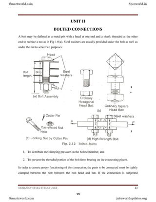
![DESIGN OF STEEL STRUCTURES 31
As stated in Fig, these are the bolts made of high tensile steel which are pretensioned and then
provided with nuts. The nuts are clamped also. Hence resistance to shear force is mainly by
friction.
There are two types of HSFG bolts. They are parallel shank and waisted shank type. Parallel
shank type HSFG bolts are designed for no-slip at serviceability loads. Hence they slip at higher
loads and slip into bearing at ultimate loads. Hence such bolts are checked for their bearing
strength at ultimate load. Waisted shank HSFG bolts are designed for no slip even at ultimate
load and hence there is no need to check for their bearing strength.
Vnsf = µf ne Kh F0
Where,
µf = Co-efficient of friction (Called slip factor) as specified in Table 3.1.
ne = number of effective interfaces offering frictional resistance to this slip.
[Note: ne = 1 for lap joints and 2 for double cover butt joints]
Kh = 1.0 for fasteners in clearance holes
= 0.85 for fasteners in oversized and short slotted holes and for long slotted holes located
perpendicular to the slot.
=0.70 for fasteners in long slotted holes loaded parallel to the slot.
F0 = Minimum bolt tension at installation and may be taken as Anb f0
Anb = net area of the bolt at threads
= 2
4
78
.
0 d
π
f0 = Proof stress = 0.70 fub
Smartworld.asia Specworld.in
Smartzworld.com jntuworldupdates.org
31](https://image.slidesharecdn.com/steel-structures-design-and-drawing-210404124515/85/design-drawing-steel-structures-31-320.jpg)