( 2 –3 – 3 )
Dr. M. Y. Al-Mandil
Office: 16 – 267
: 860 3655
: almandil@kfupm.edu.sa
Semester 062
2.
Text:
Text: 1) SteelStructures, Design & Behavior (4th
Ed.)
Salman & Johnson.
2) Manual of Steel Construction (LRFD) AISC (3rd
Ed.)
Course Objectives:
Course Objectives:
Expose students to the concepts and fundamentals
of steel design and provide design skill to undertake
design problems in Steel Construction.
3.
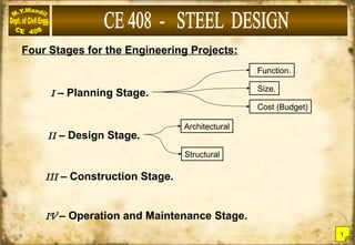
Four Stages forthe Engineering Projects:
I – Planning Stage.
Architectural
Structural
Cost (Budget)
Size.
Function.
II – Design Stage.
III – Construction Stage.
IV – Operation and Maintenance Stage.
1
4.
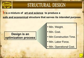
It is amixture of art and science to produce a
safe and economical structure that serves its intended purpose.
Design is an
optimization process
• Min. Weight.
• Min. Cost.
• Min Construction Time.
• Min. Labor Force.
• Min. Operational Cost.
2
5.
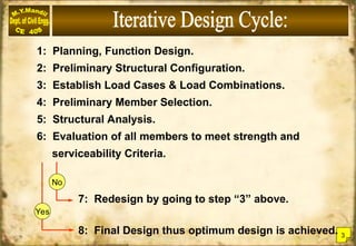
1: Planning, FunctionDesign.
2: Preliminary Structural Configuration.
3: Establish Load Cases & Load Combinations.
4: Preliminary Member Selection.
5: Structural Analysis.
6: Evaluation of all members to meet strength and
serviceability Criteria.
7: Redesign by going to step “3” above.
8: Final Design thus optimum design is achieved.
No
Yes
3
6.
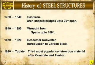
1780 - 1840Cast Iron.
arch-shaped bridges upto 30m
span.
1840 - 1890 Wrought Iron.
Spans upto 100m
.
1870 - 1920 Bessemer Converter
Introduction to Carbon Steel.
1920 - Todate Third most popular construction material
after Concrete and Timber.
4
7.
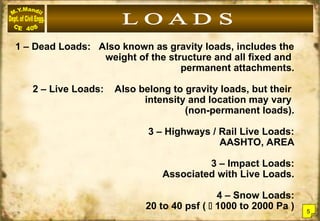
1 – DeadLoads: Also known as gravity loads, includes the
weight of the structure and all fixed and
permanent attachments.
2 – Live Loads: Also belong to gravity loads, but their
intensity and location may vary
(non-permanent loads).
3 – Highways / Rail Live Loads:
AASHTO, AREA
3 – Impact Loads:
Associated with Live Loads.
4 – Snow Loads:
20 to 40 psf ( 1000 to 2000 Pa ) 5
8.
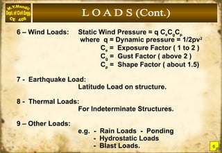
6 – WindLoads: Static Wind Pressure = q CeCgCp
where q = Dynamic pressure = 1/2pv2
Ce = Exposure Factor ( 1 to 2 )
Cg = Gust Factor ( above 2 )
Cp = Shape Factor ( about 1.5)
7 - Earthquake Load:
Latitude Load on structure.
8 - Thermal Loads:
For Indeterminate Structures.
9 – Other Loads:
e.g. - Rain Loads - Ponding
- Hydrostatic Loads
- Blast Loads. 6
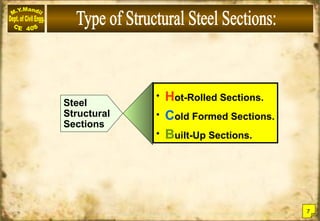
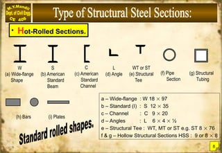
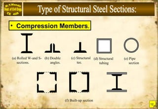
• Hot-Rolled Sections.
W
(a)Wide-flange
Shape
S
(b) American
Standard
Beam
C
(c) American
Standard
Channel
L
(d) Angle
WT or ST
(e) Structural
Tee
(f) Pipe
Section
(g) Structural
Tubing
(h) Bars (i) Plates
a – Wide-flange : W 18 97
b – Standard (I) : S 12 35
c – Channel : C 9 20
d – Angles : L 6 4 ½
e – Structural Tee : WT, MT or ST e.g. ST 8 76
f & g – Hollow Structural Sections HSS : 9 or 8 8
8
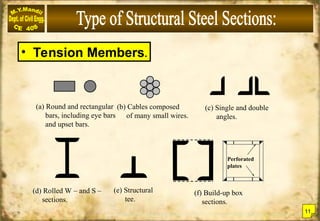
• Tension Members.
(a)Round and rectangular
bars, including eye bars
and upset bars.
(b) Cables composed
of many small wires.
(c) Single and double
angles.
(d) Rolled W – and S –
sections.
(e) Structural
tee.
(f) Build-up box
sections.
Perforated
plates
11
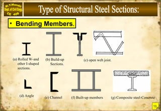
(a) Rolled W-and
otherI-shaped
sections.
(c) open web joist.
(b) Build-up
Sections.
(f) Built-up members
• Bending Members.
(d) Angle (e) Channel (g) Composite steel-Concrete
13
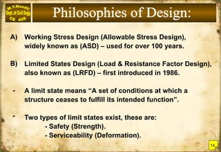
16.
Working Stress Design(Allowable Stress Design),
widely known as (ASD) – used for over 100 years.
Limited States Design (Load & Resistance Factor Design),
also known as (LRFD) – first introduced in 1986.
A limit state means “A set of conditions at which a
structure ceases to fulfill its intended function”.
Two types of limit states exist, these are:
- Safety (Strength).
- Serviceability (Deformation).
A)
B)
-
-
14
17.
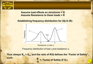
Assume load effectson structures = Q
Assume Resistance to these loads = R
Establishing frequency distribution for (Q) & (R):
Thus always Rm > Qm, and the ratio of R/Q defines the “Factor of Safety”,
such:
= Factor of Safety (F.S.).
R
Q
Frequency distribution of load Q and resistance R.
Frequency
Resistance R, Load Q
15
18.
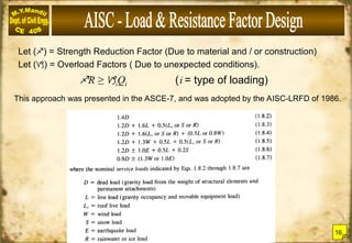
Let () =Strength Reduction Factor (Due to material and / or construction)
Let () = Overload Factors ( Due to unexpected conditions).
R ≥ iQi (i = type of loading)
This approach was presented in the ASCE-7, and was adopted by the AISC-LRFD of 1986.
16
19.
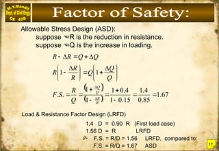
Allowable Stress Design(ASD):
suppose R is the reduction in resistance.
suppose Q is the increase in loading.
67
.
1
85
.
0
4
.
1
15
.
0
1
4
.
0
1
1
1
.
.
1
1
R
R
Q
Q
Q
R
S
F
Q
Q
Q
R
R
R
Q
Q
R
R
Load & Resistance Factor Design (LRFD)
1.4 D = 0.90 R (First load case)
1.56 D = R LRFD
F.S. = R/D = 1.56 LRFD, compared to:
F.S. = R/Q = 1.67 ASD 17
20.
ASTM (A33) Steelwith Fy = 33 ksi up to 1960.
Today steel offer wide choice of yield from 25 ksi upto 100 ksi,
among other different characteristics. The majority of construction
steels are grouped under the following main groups:
A) Carbon Steels
Carbon Steels:
low carbon [C < (0.15%)]
mild carbon [0.15% < C< 0.3%] such as A-36, A-53.
medium carbon [0.3% C < 0.6%] A-500, A-529.
high carbon [0.6% < C < 1.7%] A-570
B) High-Strength Low-Alloy Steels
High-Strength Low-Alloy Steels:
Having Fy 40 ksi to 70 ksi, may include chromium,
copper, manganese, nickel in addition to carbon.
e.g. A-242, A-441 and A-572. 18
21.
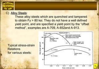
C) Alloy Steels
AlloySteels:
These alloy steels which are quenched and tampered
to obtain Fy > 80 ksi. They do not have a well defined
yield point, and are specified a yield point by the “offset
method”, examples are A-709, A-852and A-913.
Typical stress-strain
Relations
for various steels:
19
22.
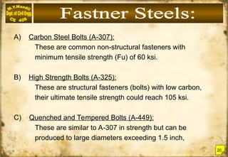
A) Carbon SteelBolts (A-307):
These are common non-structural fasteners with
minimum tensile strength (Fu) of 60 ksi.
B) High Strength Bolts (A-325):
These are structural fasteners (bolts) with low carbon,
their ultimate tensile strength could reach 105 ksi.
C) Quenched and Tempered Bolts (A-449):
These are similar to A-307 in strength but can be
produced to large diameters exceeding 1.5 inch,
20
23.
D) Heat TreatedStructural Steel Bolts (A-490):
These are in carbon content (upto 0.5%)
and has other alloys. They are quenched and
re-heated (tempered) to 900o
F.
The minimum yield strength (Fy) for these bolts
ranges from 115 ksi upto 130 ksi.
21

![ASTM (A33) Steel with Fy = 33 ksi up to 1960.
Today steel offer wide choice of yield from 25 ksi upto 100 ksi,
among other different characteristics. The majority of construction
steels are grouped under the following main groups:
A) Carbon Steels
Carbon Steels:
low carbon [C < (0.15%)]
mild carbon [0.15% < C< 0.3%] such as A-36, A-53.
medium carbon [0.3% C < 0.6%] A-500, A-529.
high carbon [0.6% < C < 1.7%] A-570
B) High-Strength Low-Alloy Steels
High-Strength Low-Alloy Steels:
Having Fy 40 ksi to 70 ksi, may include chromium,
copper, manganese, nickel in addition to carbon.
e.g. A-242, A-441 and A-572. 18](https://image.slidesharecdn.com/steeldesignce408-251015025027-22792b30/85/Steel-Design-and-RCC-structures-BCV430535-20-320.jpg)