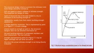
This document provides an overview of steel structure design. It discusses the types of steel structures like truss, frame, grid and arch structures. It describes the methodology of steel design using Allowable Strength Design and Load and Resistance Factor Design. It discusses the mechanical properties of steel, concepts of limit state design for beam columns, and connections. It also provides details on the design of beams, including classifications of beams and the main considerations in beam design.
Flat slabs are reinforced concrete slabs that are supported directly by columns without beams. They provide minimum depth, fast construction, and flexible column placement. There are four main types: slabs without drops and with column heads, slabs with drops and without column heads, slabs with both drops and column heads, and typical flat slabs. Column heads increase shear strength while drops increase shear strength and negative moment capacity. Flat slab systems can be either one-way or two-way depending on span ratios and load distribution. Advantages include simple formwork, no beams, and minimum depth, while disadvantages include potential interference from drops.
Steel structures involve structural steel members designed to carry loads and provide rigidity. Some famous steel structures include the Walt Disney Concert Hall, Tyne Bridge, and Howrah Bridge. Steel structures have advantages like high strength, ductility, elasticity, and ease of fabrication and erection. The Howrah Bridge is a steel cantilever bridge that connects Howrah and Kolkata. When built, it was the 3rd longest cantilever bridge in the world. It uses steel components like I-beams, rivets, and expansion joints and was constructed between 1936-1942.
Introduction;
Reinforced brick masonry (RBM) consists of brick masonry which incorporates steel reinforcement embedded in mortar.
This masonry has greatly increased resistance to forces that produce tensile and shear stresses.
The reinforcement provides additional tensile strength, allowing better use of brick masonry's inherent compressive strength.
The two materials complement each other, resulting in an excellent structural material.
HISTORY;
Brick masonry is one of the oldest forms of building construction, and reinforcement has been used to strengthen masonry since 1813.
...
Portal frames are commonly used for single-story industrial buildings. They consist of hot-rolled columns and rafters that support roofing and siding. Rafter slopes typically range from 1 in 10 to 1 in 3. Frame spacing is 6-7.5m with heights of 6-15m. Plastic analysis is used to design portal frames to allow formation of plastic hinges and economic design. Connections require moment capacity, stiffness, rotation capacity, and economy. Haunched connections are often used at the eaves and ridge to increase moment capacity. Secondary checks consider axial force effects, buckling, fracture, and deflection.
The document discusses rigid frame systems used in high-rise buildings. It provides a history of rigid frames, an introduction to what they are, and examples of their applications. It describes the material properties and connections used. It discusses considerations for rigid frame design like behavior under lateral loads. It notes advantages like architectural freedom but also disadvantages like increased drift. It concludes with a case study on using hybrid rigid/semi-rigid frames to improve seismic performance.
This document discusses long span building structures. It defines long span as structures with spans larger than 20m that cannot be achieved with ordinary reinforced concrete structures. It lists various loads that act on structural systems including dead, live, wind, and temperature loads. It also lists common materials that can be used for long span structures such as reinforced concrete, steel, timber, and composites. Common structural forms including insitu and precast concrete, steel structures, and portal frames are discussed. Long span structures are classified into form active, vector active, section active, and surface active systems with examples provided. Design considerations for long span beams are also mentioned, noting benefits such as flexible column-free spaces. Long span buildings create large column-
This document discusses reinforced concrete columns. It begins by defining columns and different column types, including based on shape, reinforcement, loading conditions, and slenderness ratio. Short columns fail due to material strength while slender columns are at risk of buckling. The document covers column design considerations like unsupported length and effective length. It provides examples of single storey building column design and discusses minimum longitudinal reinforcement requirements in columns.
Arch is a curved structure designed to carry loads across a gap mainly by compression. The mechanical principle of the arch is precisely the same as that of the portal frame. The straight pieces of material joined by sharp bends are smoothed into a continuous curve. This increases the cost of construction but greatly reduces the stresses.
For more detail on Arch Systems and architecture engineering,
visit us - www.archistudent.net
Follow us - https://www.facebook.com/Archified-162820443787915/
Retaining walls are used at the Shraddha Vivanta Residency construction site in Mumbai for two main purposes. Cantilever retaining walls around 3.5 meters deep allow for a basement and four floors of stacked parking underneath the residential building. Additional retaining walls surround underground water tanks for suction and firefighting. The walls are located along the building perimeter and around the tank areas. Proper waterproofing of the retaining walls is important given their underground locations.
This document provides details on the design and construction of flat slab structures. It discusses the benefits of flat slabs such as flexibility in layout, reduced building height and faster construction. Key considerations for design include wall and column placement, structural layout optimization, deflection checks, crack control and punching shear. Analysis involves dividing the slab into strips and determining moment and shear distributions. Reinforcement is arranged in two directions and detailing includes reinforcement lapping and service penetrations.
information on types of beams, different methods to calculate beam stress, design for shear, analysis for SRB flexure, design for flexure, Design procedure for doubly reinforced beam,
This document discusses the design of flat slab structures. It begins by defining a flat slab as a type of slab supported directly on columns without beams. It then provides details on the types of flat slabs, their common uses in buildings, and benefits such as flexibility in layout and reduced construction time. The document goes on to discuss key design considerations for flat slabs including thickness, drops, column heads, and methods of analysis. It focuses on the direct design method and provides limitations for its use.
This document discusses two-way slabs, which are supported on all four sides or at column centerlines. It describes two main types - edge supported slabs and column supported slabs. Edge supported slabs are suitable for spans of 20-30 feet and live loads of 60-120 psf. They have increased stiffness and low deflection. Column supported slabs include flat slabs and two-way ribbed/waffle slabs. Flat slabs have no beams or column capitals and are suitable for spans of 20-30 feet. Ribbed and waffle slabs have reduced dead load and architectural beauty, with spans of 30-48 feet and live loads of 60-120 psf. The document also discusses minimum
The document discusses reinforced concrete columns, including their functions, failure modes, classifications, and design considerations. Columns primarily resist axial compression but may also experience bending moments. They can fail due to compression, buckling, or a combination. Design depends on whether the column is short or slender, braced or unbraced. Reinforcement is designed based on the column's expected loads and dimensions using methods specified in design codes like BS 8110.
1. Structural systems include architectural structures like buildings that are assemblages of components designed to support loads through interconnected members.
2. Loads on structures can be static like dead loads or dynamic like wind loads, and forces like tension, compression, bending, and shear act on structural members.
3. Common structural forms include trusses, arches, shells, frames, and cable nets which use specific geometries and materials like steel and concrete to transfer loads.
This presentation is on design of welded and riveted connections in steel structures. in this presentation we learn briefly about these connections and design terminology about these connections.
Reinforced concrete is well-suited for constructing stairs due to its fire resistance, durability, strength, and pleasing appearance. R.C.C. stairs can be designed in various forms including straight flights, inclined slabs with half landings, string beams, cranked slabs, cantilevers, and spirals. The type of stair adopted depends on the space and loading conditions. Common stair arrangements include single straight flights, inclined slabs spanning longitudinally, string beams with horizontal slab spanning, cranked slabs inducing bending and torsion stresses, cantilever stairs with central supporting walls, and spiral or helical stairs used in prestige buildings.
Prestressing is a technique where internal stresses are introduced into a material to counteract loads. In prestressed concrete, high-strength tendons placed under tension are used to put concrete structures into compression before loads are applied. There are two types of prestressing: pre-tensioning, where concrete is cast around tensioned tendons; and post-tensioning, where tendons are tensioned after concrete has set. Bonded post-tensioning permanently bonds tendons to concrete using grout, while unbonded post-tensioning allows tendon movement. Prestressed concrete provides benefits like crack control, durability, and ability to build larger structures. Common applications include bridges, buildings, dams, tanks, and nuclear containment
Cast in situ piles are concrete piles that are constructed by excavating soil and pouring concrete directly into the hole. There are several types of cast in situ piles including simplex, franki, and vibro piles. The simplex pile is most common in Bangladesh. To construct a simplex pile, a casing is installed and reinforced with rebar before concrete is poured into the casing while it is vibrated out of the ground. Cast in situ piles are preferable to driven piles in areas with noise limitations, existing structures nearby, or weak and loose soils. The construction process involves soil testing, boring, installing rebar cages, and pouring concrete through a tremie pipe.
The document discusses different types of slabs used in construction. It describes solid ground floors, suspended ground floors, upper floors, precast concrete floors, reinforced concrete slabs, flat plate slabs, waffle slabs, one-way and two-way slabs. It also discusses potential problems with slabs like cracking and dampness, and their causes such as poor construction practices, uneven settlement, inadequate strength of concrete, and improper reinforcement placement.
The document discusses reinforced cement concrete (RCC) structures. It describes two types of building structures - load bearing, where walls transmit loads directly to the ground, and framed structures, where loads are transferred through RCC beams, columns, and slabs. It also discusses design loads on buildings including dead loads from structural weight and live loads. Common RCC structural elements like beams, slabs, shear walls and elevator shafts are described. Raw materials, advantages, specifications, common ratios, one-way and two-way slabs, and examples of RCC structures are covered.
Different rolled steel bars and sectionsskytechmetals
Rolled steel sections are available in various forms for use in Steel Construction. Shapes, sizes, and properties of these rolled steel sections, Different steel members are manufactured in the factories based their usage
Waffle slabs are reinforced concrete slabs reinforced in two orthogonal directions, forming a ribbed plate. They are characterized by their total edge height, lightening block height, rib spacing, rib thickness, and compression layer thickness. Waffle slabs can adequately support distributed and point loads in two directions. Benefits include flexibility, light weight allowing longer spans, fast construction, slim depths, robustness, vibration control, thermal mass, and durability. Waffle slabs are constructed with ribs forming a grid pattern and solid fills at supports. Larger spans may use post-tensioning or joist construction. Proper design considers loads, materials, deformations, and tile installation compatibility.
This document provides an overview of steel structures. It defines steel as an alloy of iron with carbon and other elements. It then discusses the classification of steels based on carbon content and introduces the basic components of structures like beams and columns. The document outlines the advantages of steel structures such as lower costs, strength, recyclability, and flexibility. It also notes some disadvantages like maintenance costs and reduced strength in fires. Finally, it discusses common steel sections, connection types, and provides examples of famous steel buildings.
Braced steel frames are commonly used to resist lateral loads from earthquakes. There are two main types of bracing configurations: concentric and eccentric. Cross bracing provides the highest lateral stiffness compared to diagonal bracing or unbraced frames. Analysis of a sample braced steel frame model found that cross bracing reduced story drift by 87% and column shear and bending moments compared to an unbraced frame. However, axial forces in the columns increased with the addition of bracing. Response spectrum analysis accounted for multiple vibration modes while time history analysis used specific earthquake acceleration records over time. Cross bracing consistently performed best at reducing lateral deformation and forces in the frame.
Steel is widely used for structures due to its strength, light weight, and fast construction. This document introduces steel design based on the limit state method per Indian codes. It describes rolled steel sections like beams, channels, angles, and plates used in design. Key properties of structural steel like yield strength and ductility are discussed. The limit state method involves checking strength and serviceability limits under different load combinations and safety factors to ensure safety and comfort over the structure's lifetime.
This document provides an overview of structural steel design. It discusses steel as a structural material, its advantages, common sections and grades. It covers design philosophies like limit states, allowable stress design and load resistance factor design. Applications of steel and some key aspects of steel construction are presented. The history and role of codes are summarized. An overview of the LRFD manual is also provided.
This document discusses reinforced concrete design. It covers topics such as constituent materials and properties, basic principles, analysis methods, strength of concrete, stress-strain curves, modulus of elasticity, assumptions in design, failure modes, design philosophies, safety provisions, structural elements, and analysis of reinforced concrete sections. Flexural failure modes and equations of equilibrium for reinforced concrete design are also presented.
Effect of corrosion on concrete reinforcement mechanical and physical 2IAEME Publication
The document summarizes an experimental study on the effect of corrosion on the mechanical and physical properties of steel reinforcement bars in concrete. Three types of steel bars were tested: plain, deformed, and epoxy-coated deformed bars embedded in concrete with varying strengths and water-cement ratios. The bars were subjected to accelerated corrosion testing and evaluated at different corrosion stages. The results showed that corrosion reduced the yield stress, tensile strength, and ductility of the bars. It also decreased the mass, rib height, and cross-sectional area of the bars. The study demonstrated that corrosion negatively impacts the strength and durability of reinforced concrete structures over time.
Effect of corrosion on concrete reinforcement mechanical and physical 2IAEME Publication
The document summarizes an experimental study on the effect of corrosion on the mechanical and physical properties of steel reinforcement bars in concrete. Three types of steel bars were tested: plain, deformed, and epoxy-coated deformed bars embedded in concrete with varying strengths and water-cement ratios. The bars were subjected to accelerated corrosion testing and evaluated at different corrosion stages. The results showed that corrosion reduces steel bars' tensile strength and ductility. It also decreases yield stress and leads to more brittle failure. Corrosion was found to negatively impact the mechanical properties of reinforcement bars and reduce the load carrying capacity of reinforced concrete structures over time.
IRJET- Study on the Behaviour of Cold Formed Steel Frames Hollow SectionIRJET Journal
This document summarizes a study on the behavior of cold formed steel frames made using hollow channel sections. Two specimens of single bayed-two storey cold formed steel frames of 3mm thickness were tested under concentrated loading along both the major and minor axes. The frames connected along the major axis exhibited 38% higher load carrying capacity than those connected along the minor axis. Material properties of the steel sheets used were obtained through tensile coupon tests. Previous studies on buckling behavior of cold formed steel sections and behavior of connections under loading were also reviewed to inform the experimental investigation.
This document provides information about the Design of Steel Structures course taught by Prof. Durgesh Tupe. It includes the course code, credits, teaching scheme, evaluation scheme, course contents organized in 5 modules, outcomes expected after completion of the course, text books and reference books.
The key concepts covered are types of connections in steel structures, standard rolled sections, types of loads, permissible stresses and factors of safety, methods of design including working stress method, ultimate load method and limit state method. Connections can be riveted, bolted or welded. Loads include dead, live, wind, seismic, snow etc. Methods of design have moved from working stress to limit state for better economy and safety consideration
1. It discusses the advantages and disadvantages of reinforced concrete as a structural material and its wide use in structures.
2. It outlines key design assumptions used in reinforced concrete design including strain compatibility between concrete and steel, stress-strain relationships of materials, and failure conditions.
3. It describes the behavior of reinforced concrete beams under increasing loads and how cracking occurs initially in the tension side before steel reinforcement engages to resist bending.
This document discusses the design and optimization of a steel structure for supporting solar electrical panels. It begins by introducing steel structures and their advantages. It then discusses the existing traditional design process used by manufacturers, which tends to result in overdesigned and heavy structures without using analytical methods. The goal of the project is to introduce finite element analysis to provide a more optimized design that is lighter, lower cost and meets load requirements. Various steel sections will be analyzed and compared in ANSYS to determine the most effective cross section. The analysis will look at deflection, weight and cost to identify a design that maximizes stiffness while minimizing materials usage and expenses. The expected results are an optimized structural design for supporting electrical control panels that uses less material and reduces
Design details of Steel concrete composite flooring using profiled deck sheets and lightweight concrete; their bending and shear strengths and their serviceability criteria are given in this slide
This document provides an overview of steel structures including:
1. It defines steel structures as structures designed to fulfill their intended purpose during their lifetime by being adequately safe, serviceable, economical, and environmentally friendly.
2. It discusses the historical development of steel structures from early human shelters made of natural materials to modern steel structures regulated by specifications that have grown more complex over 100 years.
3. It outlines some key topics that will be covered related to steel structures including types of structural steel, types of steel structures, construction methods, current technologies, and the history of steel structures.
IRJET- Effects of Different Parameters on Inelastic Buckling Behavior of ...IRJET Journal
This document discusses a study that analyzed the buckling behavior of composite concrete-filled steel tube columns with different parameters. The study used finite element analysis to model composite columns with double I-beam cross sections. It investigated the effects of eccentric loading, slenderness ratio, and distance between steel profiles on buckling capacity. The results showed that filling steel sections with concrete delays steel yielding and increases column capacity. Greater concrete surface area and lower slenderness ratio also led to higher strength due to increased confinement effects.
CONCRETE-ENCASED CFST BEAM-COLUMN JOINTS: A REVIEWIRJET Journal
This document reviews concrete-encased concrete-filled steel tubular (CFST) beam-column joints. It discusses how beam-column joints are the most seismically affected part of framed structures, so understanding their seismic performance is important. Concrete-encased CFST beam-column joints consist of a CFST core surrounded by reinforced concrete. The document reviews the properties and performance of these joints, including different types of connections, experimental investigations that have been conducted, and the results of one experimental program that tested seismic performance and found three main failure types. In summary, concrete-encased CFST beam-column joints demonstrate favorable seismic behavior and strength due to the composite action of the steel tube and concrete.
This document summarizes a site visit by students to an Ajiya glass and metal factory. It focuses on properties of steel, which the group chose as their topic. Steel has many applications in construction like floor decks, frames, trusses, and cladding. It has advantages like strength and recyclability but disadvantages like cost and need for maintenance. The document discusses physical and chemical properties, sustainability, aesthetics, performance in fires and earthquakes, and maintenance needs to prolong steel's lifespan. It concludes the site visit benefited students' understanding of building materials.
The Structural Behaviour of Concrete Filled Steel Tubular columnsIRJET Journal
This document describes a study comparing the structural behavior of concrete-filled steel tubular columns made with different steel materials through numerical analysis and experimental testing. Six column specimens were tested - two each made with stainless steel, mild steel, and cold-formed steel tubes. Both short and long columns were analyzed. The numerical analysis found that stainless steel columns had the highest load-carrying capacity. The experimental results supported this, with stainless steel columns outperforming the other materials. There was good agreement between the numerical and experimental load values, with errors generally below 5%. The study concluded that stainless steel provided the best performance for concrete-filled steel tubular columns subjected to axial loads.
Cyclic Elastoplastic Large Displacement Analysis and Stability Evaluation of ...drboon
This paper deals with the cyclic elastoplastic large displacement analysis and stability evaluation of steel tubular braces subjected to axial tension and compression. The inelastic cyclic performance of cold-formed steel braces made of circular hollow sections is examined through finite element analysis using the commercial computer program ABAQUS. First some of the most important parameters considered in the practical design and ductility evaluation of steel braces of tubular sections are presented. Then the details of finite element modeling and numerical analysis are described. Later the accuracy of the analytical model employed in the analysis is substantiated by comparing the analytical results with the available test data in the literature. Finally the effects of some important structural and material parameters on cyclic inelastic behavior of steel tubular braces are discussed and evaluated.
Experimental study on strength and flexural behaviour of reinforced concrete ...IOSR Journals
Abstract: Strength and flexural behaviour of reinforced concrete beams using deflected structural steel
reinforcement and the conventional steel reinforcement are conducted in this study. The reinforcement quantity
of both categories was approximately equalised. Mild steel flats with minimum thickness and corresponding
width are deflected to possible extent in a parabolic shape and semi-circular shape are fabricated and used as
deflected structural steel reinforcement in one part, whereas the fabrication of ribbed tar steel circular bars as
conventional reinforcement on the another part of the experiment for comparison in the concrete beams. All the
beams had same dimensions and same proportions of designed mix concrete, were tested under two point
loading system. As the result of experiments, it is found that the inverted catenary flats and their ties, transfers
the load through arch action of steel from loading points towards the supports before reaching the bottom
fibre at the centre of the beam as intended earlier. Thereby the load carrying capacity and the ductility ratio
has being increased in deflected structural steel reinforced beams when compared with ribbed tar steel
reinforced concrete beams, it is also observed that the failure mode (collapse pattern)is safer.
Keywords --Arch profile, Conventional steel reinforcement, Cracks, Collapse, Deflected structural steel,
Ductility ratio.
“Review on Finite Elemental Analysis of Industrial Mid Rise Building Using Co...IRJET Journal
This document summarizes a research paper that analyzes the finite element analysis of an industrial mid-rise building using cold-formed steel. It begins with an abstract that outlines analyzing cold-formed steel sections using software like STADD Pro. It then reviews literature on analyzing cold-formed steel structures for seismic loading and buckling behavior. The research objectives are to analyze and compare the strength, weight, and performance of cold-formed steel sections to traditional steel sections under wind loads for a sample industrial building project using optimization techniques in STADD Pro. The full paper would analyze the sample building and compare the performance of cold-formed steel to traditional steel sections.
Steel structures are made from combinations of structural steel members designed to carry loads and provide rigidity. Common steel structures include buildings, bridges, and towers. Steel comes in various grades depending on carbon content, including low carbon steel (mild steel), medium carbon steel, and high carbon steel. Steel structures offer advantages like strength, light weight, and ease of fabrication but require maintenance to prevent corrosion. Common steel sections used in construction include I-beams, channels, angles, and hollow sections. Connections between steel members can be welded, bolted, or riveted.
Similar to Steel Structure Design (Study Report).pptx (20)
Harnessing WebAssembly for Real-time Stateless Streaming PipelinesChristina Lin
Traditionally, dealing with real-time data pipelines has involved significant overhead, even for straightforward tasks like data transformation or masking. However, in this talk, we’ll venture into the dynamic realm of WebAssembly (WASM) and discover how it can revolutionize the creation of stateless streaming pipelines within a Kafka (Redpanda) broker. These pipelines are adept at managing low-latency, high-data-volume scenarios.
Embedded machine learning-based road conditions and driving behavior monitoringIJECEIAES
Car accident rates have increased in recent years, resulting in losses in human lives, properties, and other financial costs. An embedded machine learning-based system is developed to address this critical issue. The system can monitor road conditions, detect driving patterns, and identify aggressive driving behaviors. The system is based on neural networks trained on a comprehensive dataset of driving events, driving styles, and road conditions. The system effectively detects potential risks and helps mitigate the frequency and impact of accidents. The primary goal is to ensure the safety of drivers and vehicles. Collecting data involved gathering information on three key road events: normal street and normal drive, speed bumps, circular yellow speed bumps, and three aggressive driving actions: sudden start, sudden stop, and sudden entry. The gathered data is processed and analyzed using a machine learning system designed for limited power and memory devices. The developed system resulted in 91.9% accuracy, 93.6% precision, and 92% recall. The achieved inference time on an Arduino Nano 33 BLE Sense with a 32-bit CPU running at 64 MHz is 34 ms and requires 2.6 kB peak RAM and 139.9 kB program flash memory, making it suitable for resource-constrained embedded systems.
Using recycled concrete aggregates (RCA) for pavements is crucial to achieving sustainability. Implementing RCA for new pavement can minimize carbon footprint, conserve natural resources, reduce harmful emissions, and lower life cycle costs. Compared to natural aggregate (NA), RCA pavement has fewer comprehensive studies and sustainability assessments.
Optimizing Gradle Builds - Gradle DPE Tour Berlin 2024Sinan KOZAK
Sinan from the Delivery Hero mobile infrastructure engineering team shares a deep dive into performance acceleration with Gradle build cache optimizations. Sinan shares their journey into solving complex build-cache problems that affect Gradle builds. By understanding the challenges and solutions found in our journey, we aim to demonstrate the possibilities for faster builds. The case study reveals how overlapping outputs and cache misconfigurations led to significant increases in build times, especially as the project scaled up with numerous modules using Paparazzi tests. The journey from diagnosing to defeating cache issues offers invaluable lessons on maintaining cache integrity without sacrificing functionality.
Using recycled concrete aggregates (RCA) for pavements is crucial to achieving sustainability. Implementing RCA for new pavement can minimize carbon footprint, conserve natural resources, reduce harmful emissions, and lower life cycle costs. Compared to natural aggregate (NA), RCA pavement has fewer comprehensive studies and sustainability assessments.
Comparative analysis between traditional aquaponics and reconstructed aquapon...bijceesjournal
The aquaponic system of planting is a method that does not require soil usage. It is a method that only needs water, fish, lava rocks (a substitute for soil), and plants. Aquaponic systems are sustainable and environmentally friendly. Its use not only helps to plant in small spaces but also helps reduce artificial chemical use and minimizes excess water use, as aquaponics consumes 90% less water than soil-based gardening. The study applied a descriptive and experimental design to assess and compare conventional and reconstructed aquaponic methods for reproducing tomatoes. The researchers created an observation checklist to determine the significant factors of the study. The study aims to determine the significant difference between traditional aquaponics and reconstructed aquaponics systems propagating tomatoes in terms of height, weight, girth, and number of fruits. The reconstructed aquaponics system’s higher growth yield results in a much more nourished crop than the traditional aquaponics system. It is superior in its number of fruits, height, weight, and girth measurement. Moreover, the reconstructed aquaponics system is proven to eliminate all the hindrances present in the traditional aquaponics system, which are overcrowding of fish, algae growth, pest problems, contaminated water, and dead fish.
A SYSTEMATIC RISK ASSESSMENT APPROACH FOR SECURING THE SMART IRRIGATION SYSTEMSIJNSA Journal
The smart irrigation system represents an innovative approach to optimize water usage in agricultural and landscaping practices. The integration of cutting-edge technologies, including sensors, actuators, and data analysis, empowers this system to provide accurate monitoring and control of irrigation processes by leveraging real-time environmental conditions. The main objective of a smart irrigation system is to optimize water efficiency, minimize expenses, and foster the adoption of sustainable water management methods. This paper conducts a systematic risk assessment by exploring the key components/assets and their functionalities in the smart irrigation system. The crucial role of sensors in gathering data on soil moisture, weather patterns, and plant well-being is emphasized in this system. These sensors enable intelligent decision-making in irrigation scheduling and water distribution, leading to enhanced water efficiency and sustainable water management practices. Actuators enable automated control of irrigation devices, ensuring precise and targeted water delivery to plants. Additionally, the paper addresses the potential threat and vulnerabilities associated with smart irrigation systems. It discusses limitations of the system, such as power constraints and computational capabilities, and calculates the potential security risks. The paper suggests possible risk treatment methods for effective secure system operation. In conclusion, the paper emphasizes the significant benefits of implementing smart irrigation systems, including improved water conservation, increased crop yield, and reduced environmental impact. Additionally, based on the security analysis conducted, the paper recommends the implementation of countermeasures and security approaches to address vulnerabilities and ensure the integrity and reliability of the system. By incorporating these measures, smart irrigation technology can revolutionize water management practices in agriculture, promoting sustainability, resource efficiency, and safeguarding against potential security threats.
TIME DIVISION MULTIPLEXING TECHNIQUE FOR COMMUNICATION SYSTEMHODECEDSIET
Time Division Multiplexing (TDM) is a method of transmitting multiple signals over a single communication channel by dividing the signal into many segments, each having a very short duration of time. These time slots are then allocated to different data streams, allowing multiple signals to share the same transmission medium efficiently. TDM is widely used in telecommunications and data communication systems.
### How TDM Works
1. **Time Slots Allocation**: The core principle of TDM is to assign distinct time slots to each signal. During each time slot, the respective signal is transmitted, and then the process repeats cyclically. For example, if there are four signals to be transmitted, the TDM cycle will divide time into four slots, each assigned to one signal.
2. **Synchronization**: Synchronization is crucial in TDM systems to ensure that the signals are correctly aligned with their respective time slots. Both the transmitter and receiver must be synchronized to avoid any overlap or loss of data. This synchronization is typically maintained by a clock signal that ensures time slots are accurately aligned.
3. **Frame Structure**: TDM data is organized into frames, where each frame consists of a set of time slots. Each frame is repeated at regular intervals, ensuring continuous transmission of data streams. The frame structure helps in managing the data streams and maintaining the synchronization between the transmitter and receiver.
4. **Multiplexer and Demultiplexer**: At the transmitting end, a multiplexer combines multiple input signals into a single composite signal by assigning each signal to a specific time slot. At the receiving end, a demultiplexer separates the composite signal back into individual signals based on their respective time slots.
### Types of TDM
1. **Synchronous TDM**: In synchronous TDM, time slots are pre-assigned to each signal, regardless of whether the signal has data to transmit or not. This can lead to inefficiencies if some time slots remain empty due to the absence of data.
2. **Asynchronous TDM (or Statistical TDM)**: Asynchronous TDM addresses the inefficiencies of synchronous TDM by allocating time slots dynamically based on the presence of data. Time slots are assigned only when there is data to transmit, which optimizes the use of the communication channel.
### Applications of TDM
- **Telecommunications**: TDM is extensively used in telecommunication systems, such as in T1 and E1 lines, where multiple telephone calls are transmitted over a single line by assigning each call to a specific time slot.
- **Digital Audio and Video Broadcasting**: TDM is used in broadcasting systems to transmit multiple audio or video streams over a single channel, ensuring efficient use of bandwidth.
- **Computer Networks**: TDM is used in network protocols and systems to manage the transmission of data from multiple sources over a single network medium.
### Advantages of TDM
- **Efficient Use of Bandwidth**: TDM all
Understanding Inductive Bias in Machine LearningSUTEJAS
This presentation explores the concept of inductive bias in machine learning. It explains how algorithms come with built-in assumptions and preferences that guide the learning process. You'll learn about the different types of inductive bias and how they can impact the performance and generalizability of machine learning models.
The presentation also covers the positive and negative aspects of inductive bias, along with strategies for mitigating potential drawbacks. We'll explore examples of how bias manifests in algorithms like neural networks and decision trees.
By understanding inductive bias, you can gain valuable insights into how machine learning models work and make informed decisions when building and deploying them.
1. STEEL STRUCTURE DESIGN
STUDY REPORT OF STEEL STRUCTURE DESIGN (SELF)
DEPARTMENT OF CIVIL ENGINEERING
KHAN MASUD PARVES
ID: 671913090109
2. CONTENT
• INTRODUCTION
• NOTES OF STEEL MATERIAL
• TYPES OF STEEL STRUCTURE
• METHODOLOGY
• ENVIRONMENTAL IMPLICATIONS
• MECHANICAL PROPERTIES OF STEEL
• CONCEPT OF LIMIT STEEL DESIGN OF BEAM COLUMNS
• CONNECTIONS
• DESIGN OF BEAMS
3. INTRODUCTION
A structure which is made from organized combination of structural steel
members designed to carry loads and provide adequate rigidity. Steel
structures involve substructure or members in a building made from
structural steel
Steel design, or more specifically, structural steel design, is an area
of structural engineering used to design steel structures. These structures
include schools, houses, bridges, commercial centers, tall
buildings, warehouses, aircraft, ships and stadiums. The design and use
of steel frames are commonly employed in the design of steel structures.
More advanced structures include steel plates and shells. There are
currently two common methods of steel design: The first method is
the Allowable Strength Design (ASD) method. The second is the Load and
Resistance Factor Design (LRFD) method. Both use a strength, or ultimate
level design approach.
4. NOTES ON STEEL MATERIAL
Steel is a term given to alloys containing a high proportion of iron with some
carbon. Other alloying elements may also be present in varying proportions.
The properties of steel are highly dependent on the proportions of alloying
elements, so that their levels are closely controlled during its manufacture. The
properties of steel also depend on the heat treatment of the metal.
Steel is by far the most important metal, in tonnage terms, in the modern world,
with the annual global production of over 700 million tonnes dwarfing the
approximately 17 million tonnes of the next most prolific, aluminium. The low
price and high strength of steel means that it is used structurally in many
buildings and as sheet steel it is the major component of motor vehicles and
domestic appliances. The major disadvantage of steel is that it will oxidize under
moist conditions to form rust. Typical steel would have a density of about 7.7 g
cm-3and a melting point of about 1650oC.
7. STEEL DESIGN SPECIFICATIONS
The specifications of most interest to the structural steel designer are those
published by the
following organizations.
• American Institute of Steel Construction (AISC)
• American Association of State Highway and Transportation Officials (AASHTO)
• American Railway Engineering and Maintenance-of-Way Association (AREMA)
• American Iron and Steel Institute (AISI)
8. METHODOLOGY
The design of a structural member entails the selection of a cross section that will safely and
economically resist the applied loads. The fundamental requirement of structural design is that the
required strength not exceed the available strength; that is,
Required strength ≤ available strength
Design for strength is performed according to the provisions for load and resistance factor design
(LRFD) or to the provisions for allowable strength design (ASD).
Allowable strength design (ASD):
In this method a member is selected that has cross‐sectional properties such as area and moment of
inertia that are large enough to prevent the maximum applied axial force, shear, or bending moment
from exceeding an allowable, or permissible, value. This allowable value is obtained by dividing the
nominal or theoretical, strength by a factor of safety.
This can be expressed as,
𝐴𝑙𝑙𝑜𝑤𝑎𝑏𝑙𝑒 strength =𝑁𝑜𝑚𝑖𝑛𝑎𝑙 𝑠𝑡𝑟𝑒𝑛𝑔𝑡ℎ
𝑆𝑎𝑓𝑒𝑡𝑦 𝑓𝑎𝑐𝑡𝑜𝑟
9. Load and resistance factor design (LRFD):
In this method load factors are applied to the service loads, and a member is selected that will have
enough strength to resist the factored loads. In addition, the theoretical strength of the member is
reduced by the application of a resistance factor. The criterion that must be satisfied in the selection
of a member is
𝐹𝑎𝑐𝑡𝑜𝑟𝑒𝑑 𝑙𝑜𝑎𝑑 ≤ 𝑓𝑎𝑐𝑡𝑜𝑟𝑒𝑑 𝑠𝑡𝑟𝑒𝑛𝑔𝑡ℎ
In this expression, the factored load is actually the sum of all service loads to be resisted by the
member, each multiplied by its own load factor. For example, dead loads will have load factors that
are different from those for live loads. The factored strength is the theoretical strength multiplied
by a resistance factor.
10. ENVIRONMENTAL IMPLICATIONS
Due to the nature of the steel making process, large amounts of solid, liquid and gaseous wastes
are generated in the steel plant. Careful planning is necessary to ensure that these do not have a
negative impact on the environment.
The steel mill requires 1.2 to 1.4 million tonnes of ironsand each year, which means that up to 10
million tonnes of pure sand must be mined. The non-magnetic sand is returned to the area from
which it was mined, and marram grass and radiata pines planted to stabilise the deposits.
Wet scrubbers and bag houses are the principal means of controlling air pollution. The wet
scrubbers (see oil refining article) wash the dust out of the hot process waste gases which result
from iron and steel making while the cloth bags inside a bag house filter dust out of the gas. The
dust collection system is shared by the steel production and steel processing sections, and
collects a total of between five and ten tonnes of dust every hour.
Extensive
11. ADVANTAGES OF STEEL DESIGN
1. Better quality control
2. Lighter
3. Faster to erect
4. Reduced site time – Fast track construction
5. Large column free space and amenable for alteration
6. Less material Handling at site
7. Less percentage of floor area occupied by structural elements
8. Has better ductility and hence superior lateral load behavior, better earthquake
performance
12. DISADVANTAGES OF STEEL DESIGN
1. Skilled labor is required
2. Higher cost of construction
3. Maintenance cost is high (Due to corrosion)
4. Poor fire proofing as at 1000o
F (538oC) 65% and at 1600o
F (871oC) 15% of strength
remains
5. Electricity may be required (to hold joints, etc.)
13. MECHANICAL PROPERTIES OF STEEL
Stress – strain behavior: tensile test
The stress-strain curve for steel is generally obtained from tensile test on standard specimens as
shown in Figure below. The details of the specimen and the method of testing is elaborated in IS: 1608
(1995). The important parameters are the gauge length „Lc‟ and the initial cross section area So. The
loads are applied through the threaded or shouldered ends. The initial gauge length is taken as 5.65
(So) 1/2 in the case of rectangular specimen and it is five times the diameter in the case of circular
specimen. A typical stress-strain curve of the tensile test coupon is shown in Fig.1.5 in which a sharp
change in yield point followed by plastic strain is observed. After a certain amount of the plastic
deformation of the material, due to reorientation of the crystal structure an increase in load is
observed with increase in strain. This range is called the strain hardening range. After a little increase
in load, the specimen eventually fractures. After the failure it is seen that the fractured surface of
the two pieces form a cup and cone arrangement. This cup and cone fracture is considered to be an
indication of ductile fracture. It is seen from Fig.1.5 that the elastic strain is up to ey followed by a
yield plateau between strains ey and esh and a strain hardening range start at esh and the specimen
fail at eult where ey, esh and eult are the strains at onset of yielding, strain hardening and failure
respectively.
14. Depending on the steel used, εsh generally varies between 5 and 15 εy, with an average value of 10 εy typically used in
many applications. For all structural steels, the modulus of elasticity can be taken as 205,000 MPa and the tangent
modus at the onset of strain hardening is roughly 1/30th of that value or approximately 6700 MPa. High strength steels,
due to their specific microstructure, do not show a sharp yield point but rather they yield continuously as shown in Fig.
1.6. For such steels the yield stress is always taken as the stress at which a line at 0.2% strain, parallel to the elastic
portion, intercepts the stress strain curve. This is shown in Fig.1.6.
The nominal stress or the engineering stress is given by the load divided by the original area. Similarly, the engineering
strain is taken as the ratio of the change in length to original length.
15. MECHANICAL PROPERTIES FOR MATERIALS
Some are commonly or mostly preferred properties are
1. Stiffness
2. Elasticity
3. Plasticity
4. Ductility
5. Brittleness
6. Malleability
7. Toughness
8. Hardness
9. Creep
10. Fatigue
16. CONCEPT OF LSD OF BEAM COLUMNS
Steel structures are important in a variety of land-based applications, including industrial (such
as factory sheds, box girder cranes, process plants, power and chemical plants etc.),
infrastructural (Lattice girder bridges, box girder bridges, flyovers, institutional buildings,
shopping mall etc.) and residential sector. The basic strength members in steel structures include
support members (such as rolled steel sections, hollow circular tubes, square and rectangular
hollow sections, built-up sections, plate girders etc.), plates, stiffened panels/grillages and box
girders. During their lifetime, the structures constructed using these members are subjected to
various types of loading which is for the most part operational, but may in some cases be
extreme or even accidental.
Steel-plated structures are likely to be subjected to various types of loads and deformations
arising from service requirements that may range from the routine to the extreme or accidental.
The mission of the structural designer is to design a structure that can withstand such demands
throughout its expected lifetime.
17. The structural design criteria to prevent the Ultimate Limit
State Design (hereafter termed as
ULS) are based on plastic collapse or ultimate strength.
The simplified ULS design of many
types of structures has in the past tended to rely on
estimates of the buckling strength of
components, usually from their elastic buckling strength
adjusted by
a simple plasticity correction. This is represented by point
A in Figure 7.1. In such a design
scheme based on strength at point A, the structural
designer does not use detailed information on
the post-buckling behavior of component members and
their interactions. The true ultimate
strength represented by point B in Figure 7.1 may be
higher although one can never be sure of
this since the actual ultimate strength is not being directly
evaluated
18. Ultimate Limit State Design of Steel Structures reviews
and describes both fundamentals and practical design
procedures in this field. Designs should ensure that the
structure does not become unfit / unserviceable for the
use for which it is intended to. The state at which the
unfitness occurs is called a limit state.
Figure 7.2 shows how limit-state design employs separate
factors γf,
which reflects the combination of variability of loading γl,
material strength γm and structural performance γp.
In the elastic design approach, the design stress is
achieved by scaling down the strength of material or
member using a factor of safety γe as indicated in Figure
7.2, while the plastic design compares actual structural
member stresses with the effects of factored-up loading
by using a load factor of
γp.
19. Special features of limit state design method are:
• Serviceability and the ultimate limit state design of steel structural systems and
their components.
• Due importance has been provided to all probable and possible design conditions
that could cause failure or make the structure unfit for its intended use.
.The basis for design is entirely dependent on actual behaviour of materials in structures and the
performance of real structures, established by tests and long-term observations
• The main intention is to adopt probability theory and related statistical methods in the design.
• It is possible to take into account a number of limit states depending upon the particular
instance.
• This method is more general in comparison to the working stress method. In this method,
different safety factors can be applied to different limit states, which is more rational and
practical than applying one common factor (load factor) as in the plastic design method.
• This concept of design is appropriate for the design of structures since any development in the
knowledge base for the structural behavior, loading and materials can be readily implemented.
20. CONNECTIONS
Now I’m going to introduce new topic name is
„connections‟. When we are going to design a steel
structure completely, first we have to know the
elementary design. Elementary design means design of
Beam member (flexural member), Design of a
compression member (Column member), Design of a
tension member, Base plate, the foundations and
similarly the
„Connections‟.
The utility of the connection is that to withstand the
load and to transfer the load from one member to
another member. Like suppose beam and column. Now
the load from beam to column is going to pass through
that joint. If joint is not sufficiently strong then chances
of failure will be there. In general we see we use to give
much importance on design of different types of
elements.
We must give due importance to the connection
aspects because steel structure may fail, if their
connections are improper. So the beam member or
the column member may be strong enough to send
the load. If their joint is weak, then as rule the
structure will fail. So we have to consider the
connections as important so that failure doesn‟t occur
at the joint level.
21. I am just showing one picture. Say suppose one column is there and another beam is here. So
how to connect it. So this is a column and this is a beam. Now connection is to be made. So what
we used to do? That connections can be made either temporarily or permanent in nature. Say
suppose we are providing some bolted or riveted connection to with stand the load coming from
the beam to column.
22. DESIGN OF BEAMS
A structural member subjected to transverse loads (Loads
perpendicular to its longitudinal axis) is called a beam. See
Figure ABOVEBeams are most critical members in any structure.
Their design should therefore not only be economical but also
safe.
The main considerations in the design of beams are:
1. They should be proportioned for strength in bending keeping
in view the lateral and local stability of the compression flange
and the capacity of the selected shape to develop the
necessary strength in shear and local bearing.
2. They should be proportioned for stiffness, keeping in mind
their deflections and deformations under service conditions.
3. They should be proportioned for economy, paying attention
to the size and grade of steel to yield the most economical
design.
23. Beam design consists merely of the provision of adequate bending and shear
resistance. For optimum bending resistance, as much of the beams material
as possible should be displaced as far as practicable from the neutral axis.
The web area should be sufficient to resist shear.Maximum moment and
maximum shear usually occur at different sections. Though simple in
design, the lateral buckling of beam as a whole, or of its compression flange
or its web pose complications. Another problem is of proper depth – an
increase in depth may be desirable for moment resistance, it may at the
same impair resistance to lateral or web buckling (Figure).
24. TYPES OF BEAMS
Beams are generally classified according to their geometry and
the manner in which they are supported. They may be straight or
curved
Girders- usually the most important beams which are frequently
at wide spacing.
Joists- usually less important beams which are closely spaced,
frequently with truss type webs.
Stringers- Longitudinal beams spanning between floor beams.
Purlins- Roof beams spanning between trusses
Girts- horizontal wall beams serving principally to resist bending
due to wind on the side of an industrial building.
Lintels- Members supporting a wall over window or door
openings.