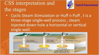
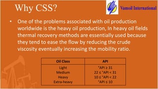
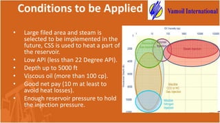
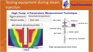
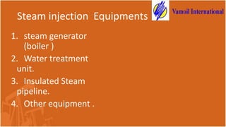
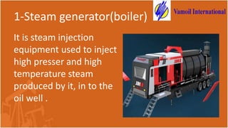
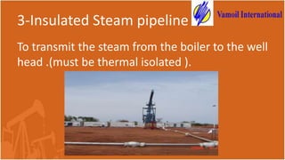
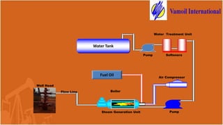
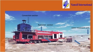
Cyclic Steam Stimulation
Prepared by :ENG:Mahmoud Zohair
ENG:Shareef Ali
Overview
• Enhanced oil recovery (EOR)
• Impotents of EOR
• CSS interpretation and the stages
• Why CSS?
• Testing equipment during steam
injection
• Steam injection Equipments
Enhanced oil recovery
(EOR)
• Enhanced oil recovery (EOR) processes include
all methods that use to improves oil recovery by
changing the properties of the displacing or
displaced fluids
Impotents of EOR
CSS interpretation and
the stages
• Cyclic Steam Stimulation or Huff n Puff , t is a
three-stage single-well process , steam
injected down hole a horizontal or vertical
single well.
Why CSS?
• One of the problems associated with oil production
worldwide is the heavy oil production, In heavy oil fields
thermal recovery methods are essentially used because
they tend to ease the flow by reducing the crude
viscosity eventually increasing the mobility ratio.
Oil Class API
Light
Medium
Heavy
Extra-heavy
°API ≥ 31
22 ≤ °API < 31
10 ≤ °API < 22
°API ≤ 10
Conditions to be Applied
• Large filed area and steam is
selected to be implemented in the
future, CSS is used to heat a part of
the reservoir.
• Low API (less than 22 Degree API).
• Depth up to 5000 ft
• Viscous oil (more than 100 cp).
• Good net pay (10 m at least to
avoid heat losses).
• Enough reservoir pressure to hold
the injection pressure.
Steam injection testing and equipment
Four Parameter Combined
Logging Instrument
Application
→Steam absorption profile test for high
temperature steam injection wells;
→Wellbore heat loss test for high
temperature steam injection wells;
Testing equipment during steam
injection
Steam injection Equipments
1. steam generator
(boiler )
2. Water treatment
unit.
3. Insulated Steam
pipeline.
4. Other equipment .
1-Steam generator(boiler)
It is steam injection
equipment used to inject
high presser and high
temperature steam
produced by it, in to the
oil well .
Cont Steam generator(boiler)
:
boiler sections & systems
Divided in to three sections and three systems :
systems
sections
•Water –steam system
•Combustion system
•Auto control system
•Radiation section .
•Convection section
•Transition section
2-water treatment unit
Used to extract water
hardness form raw water
using ion exchange
method to :
• Fulfill good steam quality.
• Prevent the boiler from
corrosion .
3-Insulated Steam pipeline
To transmit the steam from the boiler to the well
head .(must be thermal isolated ).
4-Other devices
•Water supplying pump
•Burner
•Air compressor
•Heater
•Separator
•Filter
•Water tank
•Fuel tank
•power supply
Classification of boiler models
No. model Vaporization
capacity
(ton/hour )
Working
pressure (MPa
/ psig)
Steam Quality
(%)
Thermal
efficiency (%)
Destinations Dimensions
(m)
weight (T)
01 JM-YZG9.2 /
21-Y / Q
9.2 21/3000 82 ≥88 Sled base /
Trailer
16.5 × 3.3 × 4.3 47.4
02 JM-YZG11.5-
21-Y / Q
11.5 21/3000 82 ≥88 Sled base /
Trailer
16.8 × 3.5 × 4.4 53.5
03 JM-YZG13-21-
Y / Q
13 21/3000 82 ≥88 Sled base /
Trailer
17.5 × 3.5 × 4.4 70.9
04 JM-YZG15-21-
Y / Q
15 21/3000 82 ≥88 Sled base /
Trailer
18.0 × 3.5 × 4.4 69.1
05 JM-YZG18-21-
Y / Q
18 21/3000 82 ≥88 Sled base /
Trailer
18.5 × 3.6 × 4.5 68.2
06 JM-YZG20-
17.2-Y / Q
20 21/3000 82 ≥88 Sled base /
Trailer
19.5 × 3.8 × 4.5 83.3
07 JM-YZG23-21-
Y / Q
23 21/3000 82 ≥88 Sled base 20.5 × 4.2 × 4.5 91.6
08 JM-YZG30-21-
Y / Q
30 21/3000 82 ≥88 Sled base 21.0 × 4.2 × 7.9 150.0
09 JM-YZG50-21-
Y / Q
50 21/3000 82 ≥88 Sled base 22.0 × 4.3 ×
11.7
227.9
10 JM-YZG100-
21-Y / Q
100 21/3000 82 ≥88 Sled base 28.0 × 4.8 ×
13.5
476.9
Water Tank
Water Treatment Unit
Pump Softeners
Steam Generation Unit Pump
Air Compressor
Flow Line
Well Head
Boiler
Fuel Oil
Radiation section
Convection section
Transition section
Fuel tank
water treatment unit
How it is work
• When the instrument go through the
insulating tube (φ62), the centralizer and
collecting umbrella are closed
• Centralizer controls collecting umbrella
open. When the instrument reaches the test
section – oil layer casing (φ160),
• the centralizer is open, as well as collecting
umbrella.
• The fluid is forced to flow into flowmeter
under the control of collecting umbrella,
then the high-temperature
• steam entirely adhere to the meter ,which
improves steam flow measurement
accuracy.

Steam injection equipments.pptx

  • 1.
    Cyclic Steam Stimulation Preparedby :ENG:Mahmoud Zohair ENG:Shareef Ali
  • 2.
    Overview • Enhanced oilrecovery (EOR) • Impotents of EOR • CSS interpretation and the stages • Why CSS? • Testing equipment during steam injection • Steam injection Equipments
  • 3.
    Enhanced oil recovery (EOR) •Enhanced oil recovery (EOR) processes include all methods that use to improves oil recovery by changing the properties of the displacing or displaced fluids
  • 4.
  • 5.
    CSS interpretation and thestages • Cyclic Steam Stimulation or Huff n Puff , t is a three-stage single-well process , steam injected down hole a horizontal or vertical single well.
  • 6.
    Why CSS? • Oneof the problems associated with oil production worldwide is the heavy oil production, In heavy oil fields thermal recovery methods are essentially used because they tend to ease the flow by reducing the crude viscosity eventually increasing the mobility ratio. Oil Class API Light Medium Heavy Extra-heavy °API ≥ 31 22 ≤ °API < 31 10 ≤ °API < 22 °API ≤ 10
  • 7.
    Conditions to beApplied • Large filed area and steam is selected to be implemented in the future, CSS is used to heat a part of the reservoir. • Low API (less than 22 Degree API). • Depth up to 5000 ft • Viscous oil (more than 100 cp). • Good net pay (10 m at least to avoid heat losses). • Enough reservoir pressure to hold the injection pressure.
  • 8.
  • 9.
    Four Parameter Combined LoggingInstrument Application →Steam absorption profile test for high temperature steam injection wells; →Wellbore heat loss test for high temperature steam injection wells;
  • 10.
    Testing equipment duringsteam injection
  • 11.
  • 12.
    Steam injection Equipments 1.steam generator (boiler ) 2. Water treatment unit. 3. Insulated Steam pipeline. 4. Other equipment .
  • 13.
    1-Steam generator(boiler) It issteam injection equipment used to inject high presser and high temperature steam produced by it, in to the oil well .
  • 14.
    Cont Steam generator(boiler) : boilersections & systems Divided in to three sections and three systems : systems sections •Water –steam system •Combustion system •Auto control system •Radiation section . •Convection section •Transition section
  • 15.
    2-water treatment unit Usedto extract water hardness form raw water using ion exchange method to : • Fulfill good steam quality. • Prevent the boiler from corrosion .
  • 16.
    3-Insulated Steam pipeline Totransmit the steam from the boiler to the well head .(must be thermal isolated ).
  • 17.
    4-Other devices •Water supplyingpump •Burner •Air compressor •Heater •Separator •Filter •Water tank •Fuel tank •power supply
  • 18.
    Classification of boilermodels No. model Vaporization capacity (ton/hour ) Working pressure (MPa / psig) Steam Quality (%) Thermal efficiency (%) Destinations Dimensions (m) weight (T) 01 JM-YZG9.2 / 21-Y / Q 9.2 21/3000 82 ≥88 Sled base / Trailer 16.5 × 3.3 × 4.3 47.4 02 JM-YZG11.5- 21-Y / Q 11.5 21/3000 82 ≥88 Sled base / Trailer 16.8 × 3.5 × 4.4 53.5 03 JM-YZG13-21- Y / Q 13 21/3000 82 ≥88 Sled base / Trailer 17.5 × 3.5 × 4.4 70.9 04 JM-YZG15-21- Y / Q 15 21/3000 82 ≥88 Sled base / Trailer 18.0 × 3.5 × 4.4 69.1 05 JM-YZG18-21- Y / Q 18 21/3000 82 ≥88 Sled base / Trailer 18.5 × 3.6 × 4.5 68.2 06 JM-YZG20- 17.2-Y / Q 20 21/3000 82 ≥88 Sled base / Trailer 19.5 × 3.8 × 4.5 83.3 07 JM-YZG23-21- Y / Q 23 21/3000 82 ≥88 Sled base 20.5 × 4.2 × 4.5 91.6 08 JM-YZG30-21- Y / Q 30 21/3000 82 ≥88 Sled base 21.0 × 4.2 × 7.9 150.0 09 JM-YZG50-21- Y / Q 50 21/3000 82 ≥88 Sled base 22.0 × 4.3 × 11.7 227.9 10 JM-YZG100- 21-Y / Q 100 21/3000 82 ≥88 Sled base 28.0 × 4.8 × 13.5 476.9
  • 19.
    Water Tank Water TreatmentUnit Pump Softeners Steam Generation Unit Pump Air Compressor Flow Line Well Head Boiler Fuel Oil
  • 20.
    Radiation section Convection section Transitionsection Fuel tank water treatment unit
  • 21.
    How it iswork • When the instrument go through the insulating tube (φ62), the centralizer and collecting umbrella are closed • Centralizer controls collecting umbrella open. When the instrument reaches the test section – oil layer casing (φ160), • the centralizer is open, as well as collecting umbrella. • The fluid is forced to flow into flowmeter under the control of collecting umbrella, then the high-temperature • steam entirely adhere to the meter ,which improves steam flow measurement accuracy.