SlideShare a Scribd company logo
1 of 12
Download to read offline
www.jpsr.org Journal of Petroleum Science Research Volume 2 Issue 3, July 2013 
Current Overview of Cyclic Steam Injection 
Process 
Johannes Alvarez*1, Sungyun Han*2 
*Co-first authors are listed in alphabetical order. 
1,2 Texas A&M University, Department of Petroleum Engineering, College Station, Texas, 77843, USA 
1 johannes.alvarez@pe.tamu.edu; 2sungyun.han@pe.tamu.edu 
Abstract 
Cyclic Steam Injection (CSI) is an effective thermal recovery 
process, in which, several driving mechanisms define the 
success of the process; i.e. viscosity reduction, wettability 
alteration, gas expansion, etc. This process was first applied 
in late 1950s. Then, it has been applied world‐wide 
successfully to both light and heavy oil reservoirs. To 
increase the effectiveness of CSI, process was varied by 
chemical addition to steam, application of horizontal wells 
and introduction of hydraulic fracturing. With these modern 
technologies, average 15% of recovery factor of conventional 
CSI producers back in 1980’s boosted up to approximately 
40%. The method is attractive because it gives quick payout 
at relatively high success rate due to cumulative field 
development experiences. However, this is still 
uncompetitive in terms of ultimate recovery factor 
compared to that of other steam drive methods such as 
steam flooding (50‐60% OOIP) or SAGD (60‐70% OOIP). 
Recent studies related to the CSI have focused on either the 
optimization of chemical additives and fracture design or 
questioning on geomechanical solutions to poroelastic 
effects. In addition, most papers discuss about follow‐up 
process posterior to CSI such as in‐situ combustion, CO2 
injection and steam flooding. This study is oriented to 
overview of the past and current status of CSI process in 
technical aspects with discussion of commercial cases 
throughout the world. A summarized review is given on the 
potential importance of encouragement of further 
investigation of Cyclic Steam Injection. 
Keywords 
Cyclic Steam Injection; Cyclic Steam Stimulation; Huff n’ Puff; 
Thermal Enhanced Oil Recovery 
Introduction 
Cyclic Steam Injection, also called Huff n’ Puff, is a 
thermal recovery method which involves periodical 
injection of steam with purpose of heating the 
reservoir near wellbore, in which, one well is used as 
both injector and producer, and a cycle consisting of 3 
stages, injection, soaking and production, repeats to 
enhance the oil production rate as shown in Fig. 1. 
116 
Steam is injected into the well for certain period of 
time to heat the oil in the surrounding reservoir to a 
temperature at which it flows (200~300°C under 1 
MPa of injection pressure). When enough amount of 
steam has been injected, the well is shut down and the 
steam is left to soak for some time no more than few 
days. This stage is called soaking stage. The reservoir 
is heated by steam, consequently oil viscosity 
decreases. The well is opened and production stage is 
triggered by natural flow at first and then by artificial 
lift. The reservoir temperature reverts to the level at 
which oil flow rate reduces. Then, another cycle is 
repeated until the production reaches an economically 
determined level. 
FIG. 1 CYCLIC STEAM INEJCTINO PROCESS (FROM UNITED 
STATES DEPARTMENT OF ENERGY, WASHINGTON DC.) 
Typical CSI process is well suited for the formation 
thickness greater than 30 ft and depth of reservoir less 
than 3000 ft with high porosity (>0.3) and oil 
saturation greater than 40%. Near‐wellbore geology is 
critical in CSI for steam distribution as well as capture 
of the mobilized oil. Unconsolidated sand with low 
clay content is favorable. Above 10 API gravity and 
viscosity of oil between 1000 to 4000 cp is considerable 
while permeability should be at least 100 md (Thomas, 
2008; and Speight, 2007).
Journal of Petroleum Science Research (JPSR) Volume 2 Issue 3, July 2013 www.jpsr.org 
117 
Underlying Technology 
CSI includes three stages; injection, soaking and 
production, which are repeated until the oil 
production turns uneconomic (Prats, 1985, and 
Thomas, 2008). Application of CSI, like other EOR 
methods, targets to reduce the formation residual oil 
saturation by several driving mechanisms: viscosity 
reduction, changes in wettability and thermal and 
solution gas expansion (Prats, 1978) which depend on 
reservoir rock and fluid properties. For instance, 
viscosity reduction can be explained by mobility ratio 
which is the ratio of effective permeability to viscosity. 
In addition, during CSI many chemical reactions occur 
which mainly form gaseous components such as 
carbon dioxide, hydrogen sulfide, and hydrogen 
during steam injection (Hongfu et al., 2002); and these 
reactions include decarboxylation of the crude, 
formation of H2S from sulfur in the crude, formation 
of H2, CO, CH4 and CO2 from reactions between water 
and crude and formation of CO2 by decomposition 
and reactions of carbonates minerals (Prats, 1985). 
The produced gases formed during the CSI create 
additional driving mechanism which can be named as 
gas drive. Also, these visbreaking reactions reduce the 
oil viscosity by increasing the oil mobility (Pahlavan et 
al., 1995, Hongfu et al., 2002, and Prats, 1985). Hongfu 
et al., in 2002 reported a reduction of heavy oil 
viscosity between 28 and 42% after CSI. 
Reservoir Properties Changes with CSI 
Every stimulation that is performed in the reservoir 
has consequences; introducing heat into the formation 
by CSI produces stress and deformation in oil sand 
formations. The resulting pore volume changes affect 
the reservoir permeability and consequently water 
mobility. Scott et al., in 1994, claimed that the volume 
and permeability changes are the results of three 
effects: change in the mean principal effective stress, 
change in the shear stress and change in temperature. 
The increase in temperature causes thermal expansion 
of the sand grains and sand structure. In addition, 
studies conducted in Cold Lake field in Canada 
concluded that, during steam injection, the increase of 
pore pressure decreases the effective confining stress 
and causes an unloading of the reservoir (Scott et al., 
1994). 
In the Clearwater formation in Canada, the effects of 
the volumetric expansion, during CSI, were 
transferred to the reservoir surrounding and the 
surface (Walters et al., 2000). This is sometimes 
observed as small elevations of the surface near the 
well, usually in shallow reservoirs. In addition, 
Walters et al., 2002 explained pressure changes in an 
isolated aquifer overlying the Clearwater formation as 
the result of poroelastic effects during CSI. However, 
these geomechanical deformations and failure 
mechanisms produced by CSI give the initial 
injectivity required for steam injection and the drive 
energy needed for the oil production (Yuan et al., 
2011). 
CSI, due to the injection of a hot fluid into the 
formation, causes shear dilation (Wong et al., 2001). 
Hence, the pore rock characteristics change by means 
of enlarging their volume. This increases permeability 
which affects directly steam and hydrocarbon 
movements in the reservoir. Wong et al.. developed a 
model that provided a quantitative estimation of the 
permeability changes caused by shear dilation. 
Yale et al. affirmed that the most significant impact of 
dilation due to CSI is an increase in the permeability 
to water. This increase of the pore space is caused 
dilatation and mobility of the injected fluid. Further, 
condensation of hot water from steam ahead of the 
steam front pressurized the reservoir (Yale et al., 2010). 
Moreover, CSI induced displacements in the reservoir 
due to dilation and the recovery of these original 
conditions during production operations is a point of 
supply of reservoir drive energy. 
Gronseth, in 1989, studied the distribution of the 
injected fluids during CSI in the Clearwater formation, 
and found that if the injection rates are faster than 
diffusion rates into the matrix, the reservoir volume 
increases to adjust the volume of the injected fluid. 
This volume increase is translated into a pressure 
increase. Later, during production, reservoir pressure 
reduces and effective stresses increases, so the 
reservoir contracts and a portion, but not the entire 
increased reservoir volume, is recovered (Gronseth, 
1989). 
There are techniques used to monitor reservoir 
deformation. These measures are important to 
optimize production and design parameters such as 
well length, well spacing, injection rate, cycle time, 
among others. In CSI, inclinometers and tilt‐meters, 
based on surface deformation, are used to monitor 
steam migration and formation dilation (Du et al., 
2005). However, tilt‐meters are more accurate than 
inclinometers by more than one order of magnitude 
(Dusseault et al., 2002).
www.jpsr.org Journal of Petroleum Science Research Volume 2 Issue 3, July 2013 
History: Commercial Cases 
CSI was first used fortuitously in Venezuela in 1959. 
By that time, one of the steam injector wells began to 
produce, after a blowout, in much better conditions 
than the surrounding production wells (Trebolle and 
Chalot, 1993). Since then, this method has been 
applied in many fields such as Bolivar Coastal and 
Santa Barbara in Venezuela (Valera et al., 1999), Cold 
Lake Oil Sands in Canada, Xinjiang and Liaohe in 
China (Liguo et al., 2012), Midway‐sunset in 
California (Jones et al., 1990), among other heavy oil 
fields. 
At the early stages of CSI application, CSI was 
considered as an old‐school oil production method in 
which operations are ahead of research developments 
(Ramey et al., 1969). The literature shows that many 
publications, explaining CSI processes, were based on 
field experiences rather than research work. There are 
a lot of unknowns about the process parameters such 
as the number of stimulation cycles, well orientation 
and number of wells, operating condition, the increase 
of water cut, among others. Therefore, on early CSI 
field applications, the process was performed as trial‐and‐ 
118 
error field‐scale experiment (Ramey, 1967). After 
many research studies and field experiences, 
important technology problems were reduced. 
First, the number of stimulation cycles increased by 
time. By 1974, CSI has an average of three stimulation 
cycles with a maximum reported of 22 (Ali et al., 1974). 
In 1990, in the Midway‐Sunset field, California, there 
was already a well with 39 cycles. Also, out of 1500 
wells, there were 75 wells with more than 30 cycles, 
and 350 wells with more than 20 cycles (Jones et al., 
1990). This increment in the number of cycles was 
accomplished by getting better understanding of 
steam properties, reservoir characteristics, and 
injection conditions. 
Second, well orientation and number of wells were 
improving by time. In Trinidad and Tobago, slim‐hole 
injectors, insulated tubing and packers, and limited 
entry perforations have been used to combat gravity 
segregation consequences (Khan, 1992). As well, 
steam was injected with foam‐diverting agents to 
control water breakthrough resulting from high 
injectivity. 
In addition, in the Cold Lake oil sands, Canada, steam 
distribution in horizontal wells was improved by 
using screen sections, which facilitated contact 
between the well and the reservoir. Also, inside these 
screen sections, small flow orifices were used to 
control the flow between the inner pipe and the 
reservoir to enhance oil production and reduce steam 
consumption (Oil and Gas Journal report by Bob 
Tippee, 2012). 
In China, the most up to date methods and techniques 
used in CSI include: high‐efficient steam injection by 
automatic controlling steam generation, insulating 
surface pipeline and multi‐zone steam injection; as 
well as artificial lifting, sand control, CSI with 
chemical additives, re‐entry drilling technology, and 
process control systems (Haiyan et al., 2005). In 
addition, steam distribution has been improved by 
using separated‐zone steam injection techniques such 
as selected, dual and multi zone injection, either 
sequentially or simultaneously. This method showed, 
in field testing to 76 wells of the Liaohe oil field, an 
increase up to 70% of the steam zone (Liguo et al., 
2012). Moreover, as well in horizontal well, the tubing 
and annulus of the same well have been applied to 
inject to in the toe and heel separately (Liguo et al., 
2012). 
Third, operating conditions of pressure and 
temperature have adjusted to each case based on 
reservoir properties and well design. In the Cold Lake 
field, CSI has been achieved by injection at pressures 
high enough to fracture the formation (Beattie et al., 
1991). In California, specifically in Potter sands in the 
Midway‐Sunset field, a sequential steaming process 
was implemented. This approach involved heating the 
reservoir rather than heating each well separately 
(Jones et al., 1990). The wells were stimulated in rows 
from down to up dip of the reservoir. Using this 
methodology, the production per well increased up to 
a rate of 30% per year (Jones et al., 1990). 
Another technique, in pilot stage and successfully 
simulated, is the use of Top‐Injection Bottom‐ 
Production (TINBOP) whose principle is to inject 
steam at the top of the reservoir using the short well 
string and produced from the bottom of the reservoir 
using the long well string. (Morlot et al., 2007). 
Simulation studies, conducted by Morlot et al. showed 
TINBOP increased oil recovery by 57 to 93%, 
compared to conventional CSI (Morlot et al., 2007). 
One feature of this method is that there is no soaking 
period. 
Fourth, the increase of water cut is also addressed. In 
CSI, each succeeding cycle normally increases water 
cuts (Ali et al., 1974). Consequently, in the late 70’s 
there was a trend to convert these operations into
Journal of Petroleum Science Research (JPSR) Volume 2 Issue 3, July 2013 www.jpsr.org 
119 
steam drives due to the decrement in oil recovery 
(Prats, 1978). This trend has changed in the last years 
with the use of chemical additives on CSI. 
Recently, there have been important progresses in oil 
recovery using chemical addition. Although CSI 
increases oil recovery, chemical addition with CSI 
increases it even further (Ramey et al., 1967). 
Nowadays, in CSI processes, co‐injection of steam 
with gels, foams, and surfactants, among other 
chemicals, are used to increase oil production and 
reduce water production. In Russia, specifically in the 
Permian‐Carboniferous reservoirs of the Usinsk field, 
gels and foams have been injected with CSI from 2007 
to 2011, and an increase of 20‐30% oil rate and 
decreased 33‐35% water cut (Taraskin et al., 2012) 
have been observed. 
In Canada, Liquid Addition to Steam for Enhancing 
Recovery (LASER) has been field‐tested for a single 
cycle at Cold Lake field. Previous work indicated that, 
if successful, the LASER process could increase the 
recovery factor by 3 – 6% OOIP (Leaute et al., 2007). 
Similarly in Canada, other processes have been tested 
to increase CSI performance such as air injection, 
achieving 15% incremental in addition to the 12‐20% 
recovery with high pressure CSI (Jiang et al., 2010), 
and biodiesel and carbamide injection (Babadagli et al., 
2010 and Zhang et al., 2009), both used as surfactants 
to enhance the CSI efficiency. 
The field tests in Henan Oil Field, China, using 
carbamide increased oil recovery by 7% and decreased 
Residual Oil Saturation (SOR) almost by 1% (Zhang et 
al., 2009). As well, in the Bachaquero field in 
Venezuela, an ionic‐alkyl‐aryl sulfonate surfactant 
(LAAS) has been used to generate foams that enhance 
steam distribution more evenly in the reservoir by 
restricting steam to the areas with higher permeability. 
This technique has improved the production per cycle 
from 15 to 40% (Valera et al., 1999). Moreover, 
solvents have been used to improve steam injectivity 
by removing organic deposits from the rock and 
changing its wettability in Costa Bolivar, Zulia, 
Venezuela (Mendez et al., 1992). 
Finally, wettability changes in CSI due to temperature 
increase have been studied by several authors with 
different results. On one hand, there is a line of 
thought which assures that as temperature increases, 
the system oil‐water‐rock becomes more water‐wet 
(Prats, 1985, Schembre et al., 2006, Kovscek et al., 2008, 
and Poston et al., 1970). On the other hand, another 
tendency advocates that the system becomes more oil‐wet 
as temperature increases (Rao and Karyampudi, 
1999, Escrochi et al., 2008, and Rao, 1999); also, there is 
a third line of thought explaining that wettability is 
independent of temperature changes (Miller and 
Ramey, 1985, and Pollkar et al., 1989). 
Studies with Diatomaceous rocks and Berea 
sandstones conducted by Schembre et al., 2006, 
showed that both diatomaceous and Berea cores 
become more water‐wet as temperature increases 
(from 100 to 200°C). This behavior was attributed to 
fines detachment, in low salinity and high pH steam 
condensate fluid, which stabilizes a thin water film 
that covers the rock surface avoiding contact with the 
oil phase. This fines detachment depends on 
temperature and mineralogy; for example, wettability 
changes are reached faster in silica than that in clays 
(Schembre et al., 2006). In addition, Poston et al., 1970, 
conducted similar studies using unconsolidated sands 
from Houston sands and Midway‐Sunset field, 
California, reaching the conclusion that increasing 
temperature (from 25 to 150°C) is determined in 
improving water‐wetness in the unconsolidated sands. 
On the other hand, Rao and Karyampudi, 1999, and 
Rao, 1999, conducted CSI lab and field test in the 
heavy oil and bitumen Elk Point Cummings formation, 
Canada. Their results showed that at high 
temperatures (162 to 196–°C), the formation, which is 
mainly silica (87%), became oil‐wet. Moreover, they 
also discover that salt deposition, mainly calcium 
carbonate (CaCO3), in one of the core layers prevented 
oil‐wet behavior at high temperatures, changing the 
wettability to water‐wet. This effect was proved in 
core flooding and field test in which increment in oil 
rate and decrement in water cut were observed (from 
22 BPD and 83% in the fourth cycle to 51 BPD and 77% 
in the five cycle) (Rao and Karyampudi, 1999). 
Wettability reversal effect at high temperatures is also 
attributed to asphaltene precipitation. Using 
Athabasca bitumen and live oil sample with 5% and 
3.17% asphaltene respectively, Escrochi et al., 2008, 
showed that from 150 to 400 °C the system shifted to 
oil‐wet until asphaltene precipitation was completed 
and then wettability was changed to water‐wet. 
Moreover, in the literature, results showed that 
temperature do not impact wettability during CSI, 
and Miller and Ramey, 1985 tested the unconsolidated 
Ottawa Silica Sand and a consolidated Berea 
Sandstone with temperatures from 25 to 150° C, 
concluding that there were not changes in residual
www.jpsr.org Journal of Petroleum Science Research Volume 2 Issue 3, July 2013 
saturations that imply variance in wettability. The 
same results were reached in the unconsolidated silica 
sands at 125 to 175 °C by Pollkar et al., 1989. 
Consequently, when CSI is applied, there are different 
positions in describing wettability mechanism and 
their changes with temperature. However, it is 
important to point out that these results mainly 
depend on the chemical properties of fluids injected, 
asphaltene content and the mineralogy of the 
reservoir. 
From its early stages until today, CSI has evolved 
significantly from a process discovered by chance 
where trial and error governed the operations with 
little number of cycles and low recovery factor to 
state‐of‐the‐art applications with a great variety of 
chemical additives and well geometries which 
increase the number of cycles and the ultimate oil 
recovery. However, more research needs to be done in 
evaluating wettability changes at field scale to 
determine the factors that influence early water break 
and reduce oil production at different mineralogy and 
injection temperatures. 
Current State-of-the-art: Applications 
The method is quite effective, especially in the first 
few cycles providing quick payout. However, ultimate 
recovery by cyclic steam injection is low (10‐40% of 
Original Oil in Place, OOIP), compared to that of 
steam flooding and Steam Assisted Gravity Drainage 
(SAGD) which are over 50% of OOIP (Thomas, 2008; 
Speight, 2007; Xia and Greaves, 2006) as shown in 
TABLE. 1. Therefore, it is quite common for wells to 
be produced in the cyclic steam manner for a few 
cycles before put on a steam flooding regime with 
other wells (Alikhlalov et al., 2011). 
TABLE 1 OIL RECOVERY RATE OF THERMAL EOR METHODS 
120 
Oil Recovery Factors 
(successful projects) 
Thermal EOR % of OOIP 
CSI 10 ‐ 40 
Steam flooding 50 ‐ 60 
SAGD 60 ‐ 70 
In‐situ Combustion* 70 ‐ 80 
*In‐situ Combustion using THAI—‘Toe‐to‐Heel Air Injection’ 
Conventional CSI process usually has average 
recovery factor lower than 20%. However, this can be 
doubled with combination of unconventional 
technologies which have become profitable including 
co‐injection of steam with chemical additives, 
directional drilling, and hydraulic fracturing. Recently, 
technical aspects like injected steam/produced oil ratio, 
presence of water cut in the producing well and 
excessive heat losses have required special attention. 
Many literatures have presented studies on these 
areas at laboratory scale (i.e, Castro et al., 2010). 
Investigations have been optimizing the cyclic steam 
injection technology by chemical addition to the steam. 
Currently, the performance of CSI is enhanced by co‐injection 
of steam with chemicals such as surfactants, 
solvents, miscible and immiscible gases. 
CSI with Chemical Additives 
Since 1960, investigations on cyclic steam injection 
technology have been conducted to improve recovery 
factor by adding chemical additives to steam, 
fracturing, and placing horizontal wells for different 
types of reservoir. In the reservoir, the chemical 
additives enhance the production by increasing the 
mobility of oil and enabling condensed water to carry 
higher loading of oil. Numerous studies on chemical 
additives to steam have been conducted to affect 
heavy oil properties favorably such as solvents, 
surfactants, miscible and immiscible gases. 
1) Solvents 
The idea of adding solvents to the steam to reduce 
the oil viscosity has been reported in the literature 
since 1970s. Previously, solvents and light crudes 
had been used as diluents to optimize pumping 
and pipeline transportation of heavy crudes. Both 
laboratory and field tests later years proved that 
the use of solvent as an additive to steam during 
in‐situ recovery improved the mobility ratio of 
displacing and displaced fluid and sweep 
efficiency. The mechanism is following: the 
vaporized solvent is co‐injected with steam and 
travels with the steam front. It condenses and 
mixes with the oil in the cooler regions of reservoir 
creating a transition zone of lower‐viscosity fluid 
between steam and oil. Consequently, the mobility 
ratio between steam and oil increases, resulting in 
higher production rate. 
The success of process depends on the solvent type, 
treatment size and the solvent placement. It was 
concluded that the use of small quantities of 
medium volatile solvent (no more than 10% of 
steam volume) creates the best effectiveness in 
increasing total oil production (Shu and Hartman, 
1988). In many of the previous researches, naphtha
Journal of Petroleum Science Research (JPSR) Volume 2 Issue 3, July 2013 www.jpsr.org 
121 
was employed quite frequently which was found 
to be highly effective in opening a steam flow path 
due to its high volatility. Other solvents that were 
used in recent researches include CO2, ethane, and 
a mixture of gases (Yongtao et al., 2011), kerosene, 
and even some effluents from some refinery 
processes (Castro et al., 2010). 
2) Surfactants 
Although adding solvents to steam can increase 
production recovery up to 30% upon earlier cycles, 
high injection volumes are required to reduce the 
viscosity of oil appreciably thereby necessitating 
solvent recovery, which leads to high operational 
costs. Therefore, adding surfactants to injected 
steam to reduce oil‐water interfacial tension and 
alter wettability and therefore increase recovery 
was introduced. Most widely used agent is called 
Thin Film Spreading Agents (TFSA). TFSA 
compounds reduce interfacial tension by the 
application of a spreading film strong enough to 
overcome the emulsifying agents naturally found 
between the oil‐water and oil‐rock interfaces. By 
reduction of the interfacial energies between the 
oil‐rock and water‐rock, water wetting of the rock 
results, leading to the release of oil particles from 
the rock surface improving oil mobility (Adkins et 
al., 1983). Successful field applications of TFSA in 
California and Alberta were reported with 
indication of significant improvement in heavy oil 
recovery factor up to 20% (Srivastava and Castro, 
2011). 
The capability of the steam‐surfactant mixture to 
divert steam entry into the sands varies directly 
with the concentration of the surfactant present, 
steam quality and the addition of a non‐condensable 
gas. Some pilot tests in Bolivar Coast, 
Venezuela, reported the optimum level of 
surfactant concentration in the steam liquid phase 
1 to 1.3 % (Robaina et al., 1988) above which no 
additional diversion was obtained. Most 
conventional surfactant injection projects, steam 
quality maintained averagely 60 to 70% (Blair et al 
1982; Adkins et al., 1983). Co‐injections of more 
efficient surfactants were also tested; however, 
they required high steam quality as 80 to 90%, 
which causes higher operating costs. Srivastava 
and Castro reported that TFSA requires only small 
amount of concentration (250 ppm) while 
sustaining steam quality as below 70% (Srivastava 
and Castro, 2011). Additionally, some laboratory 
tests demonstrated that introducing non‐condensable 
gases (i.e nitrogen) helps to stabilize 
the foam, affording greater plugging of the porous 
media consequently (Robaina et al., 1988). 
CSI with Horizontal Well 
Due to the presence of certain sand volumes at the 
bottom of the reservoir which is not recoverable by 
using vertical wells, the idea of horizontal well was 
introduced to the CSI process. The main advantages of 
the horizontal wells are improved sweep efficiency, 
increased producible reserves as well as steam 
injectivity, and decreased number of well required for 
field development (Joshi, 1991). Although most of 
simulation studies proved notable advantages of 
horizontal well over vertical well (Adegbesan 1992, 
and Chang et al., 2009), CSI with horizontal well had 
little success in fields before 2000s. The main reason 
was the extra operating costs which were double that 
of vertical wells back then. Other factors include 
geological/reservoir characteristics and operational 
aspects such as uneven steam distribution and sand 
productions. For example, the activity of horizontal 
drilling in Bachaquero field in Venezuela where high 
oil viscosity (~18000 cp) encountered did not appear 
profitable, causing a low annular fluid level (Mendoza 
et al., 1997). A simulation study later on also showed 
that the application of horizontal well in same field 
was not economically attractive (Escobar et al., 2000). 
On the other hand, few pilot tests in early 2000s had 
success on horizontal well application; and indeed, 
those horizontal producers in comparison to typical 
vertical ones in each area improved production 
performance and thermal efficiency as well as 
operating costs. Representative pilots are in South 
Midway‐Sunset field (McKay et al., 2003) and 
Cymric/McKittric field in California (Cline et al., 2002). 
Both fields showed about 20 to 50% improvement in 
production over results from vertical wells and 
benefited from maximum 45% of directional drilling 
cost reduction relative to that of a decade ago. 
Despite the reduced drilling costs, operating costs for 
generating steam still remains high due to greater heat 
loss when steam injection is schemed to horizontal 
well application. Further investigations inquire 
possibilities to address the solutions to this problem. 
Chang et al., examined in his simulation study the co‐injection 
with solvent (n‐hexane C6H14) and alternate 
solvent/steam cycles to reduce total number of cycles. 
(Chang et al,. 2009).
www.jpsr.org Journal of Petroleum Science Research Volume 2 Issue 3, July 2013 
CSI with Hydraulic Fracturing 
The idea of combining cyclic steam stimulation with 
hydraulic fracturing came out when both steam 
injection and completion (i.e, sand control completion) 
techniques generated potential formation damage 
thus, the permeability near the wellbore creating a 
choke was lowered that further reduces the oil 
mobility. Creating fractures allows a more efficient 
placement of injected steam, heating up larger volume 
of reservoir and reducing residual oil saturation. This 
combination is usually considered for low‐permeability 
122 
heavy oil reservoirs like California 
diatomite (0.1‐0.5 md) or Athabasca oil sands (~2.5 d). 
Several studies reported desirable results (Manrique et 
al., 1996, and Settari et al., 1981). 
Fines and sand production problems are found 
commonly during cyclic steam injection. The recent 
study investigated the efficiency of fracturing with 
viscoelastic surfactant fluid instead of water which 
worsens the sand and fine production. It was 
concluded that anionic surfactant fluids minimize gel 
damage and maintain favourable proppant 
transportation (Gomez et al., 2012). 
Follow Up Methods: Post CSI 
CSI is widely used in oil recovery due to its quick 
response; however, recovery factors are relatively low 
(10‐40% OOIP) compared to other thermal methods 
such as steam flooding (50‐60% OOIP) or in‐situ 
combustion (70‐80% OOIP) (Thomas, 2008). This is 
because the natural energy of the reservoir, as well as 
oil production, decreases and, when several cycles are 
reached, oil production tends to decrease even more 
with decreasing pressure and increasing water 
production. Consequently, some follow‐up processes 
are used after the implementation of CSI to improve 
oil recovery, such as CO2 injection (Luo et al., 2005), 
steam flooding (Yang, 2007), and air injection as in‐situ 
combustion (Gates et al., 2011, and Hajdo et al., 
1985), among others. 
One example of CO2 injection after CSI is in the 
Lengjiabao heavy oil reservoir, in which CO2 was 
injected in extra heavy oil (10,000 ‐50,000 mPa.s at 
50°C) after 3 cycles of CSI with satisfactory results; 
increasing oil mobility with CO2 utilization ratio from 
3.0 to 6.0 tons oil /tons CO2 and oil recovery from 10 to 
35% (Luo et al., 2005). However, in other wells tested 
with low permeability, porosity and oil saturation, the 
injection of CO2 did not increase oil production. 
Another thermal method frequently used as a follow 
up process for CSI is steam flooding. One of the 
experiences reported was in the Guantao formation 
(porosity and permeability relatively high and extra 
heavy oil with viscosities of 230,000 mPa∙s at 50°C) in 
the Liaohe Oil Field, China, where CSI was applied 
previously. Steam flooding was adapted by using 
horizontal wells placed between current vertical CSI 
wells (Yang, 2007). These vertical wells produced for 3 
cycles by CSI and then some of them were switched to 
steam flood as soon as the horizontal‐vertical wells 
communication was identified. Yang in 2007 reported 
that the wells have been producing since February 
2005 by steam flooding favored by gravity drainage 
forces. Initially, the predicted oil recovery by CSI was 
29% of OOIP, and, with steam flooding follow up after 
CSS, the forecasted oil recovery was 56% (Yang, 2007). 
However, steam flooding is not the right recipe as 
follow‐up after CSI for all types of formations. Every 
reservoir has its own characteristics such as vertical 
and horizontal permeabilities, reservoir properties 
changes caused by CSI, reservoir thickness, and 
viscosity of the fluids, among others, which have to be 
evaluated before steam flooding is implemented after 
CSI (He et al., 1995). 
In the Bachaquero‐01 reservoir in western Venezuela, 
CSI has been used since 1965 and currently the 
production wells have more than 6 cycles. An 
Extended Cyclic Steam Injection, which is a 
combination of steam injection and steam flooding, 
was evaluated numerically. The prediction cases were 
simulated for 7 cycles of 14 months each and 
approximately 9 months of steam flooding in different 
well patters (Chourio et al., 2011). The simulated 
results showed that there was an additional recovery 
of 3.7%, reaching the highest recovery in the area of 
24.3% of OOIP (Chourio et al., 2011). The pilot test for 
this project was planned in 2012. 
Finally, in‐situ combustion performance has also been 
numerically investigated as a follow up process for 
CSI (Gates et al., 2011). In Canada, in the Margarite 
Lake, in wells with a depth of 1476 feet and thickness 
of 112 feet (Hajdo et al., 1985) and Morgan Field, with 
wells with a depth of 670 feet and thickness of 30 feet 
(Marjerrison and Fassihi, 1995), air injection pilots 
were performed after CSI and the process were 
proved to be successful (Gates et al., 2011, Hajdo et al., 
1985 and Marjerrison and Fassihi, 1995). In addition, 
CSI was implemented in the Cold Lake oil sands, and 
the oil recovery was recorded to be 15‐20% of the
Journal of Petroleum Science Research (JPSR) Volume 2 Issue 3, July 2013 www.jpsr.org 
123 
OOIP (Nzekwu et al., 1990). Consequently, an in‐situ 
combustion process was implemented. The results, 
presented by Nzekwu et al. showed that the average 
reservoir temperature and heated zone increased after 
in‐situ combustion which consequently would 
increase oil recovery. In addition, in the heavy oil 
reservoir of Midway Field in California, a successful 
in‐situ combustion pilot was conducted in a section 
subjected to CSI for seven years (Counihan, 1977). The 
previous CSI cycles helped injectors to prevent 
burnout, clean the perforations and reduce 
spontaneous ignition. 
Currently, the most used follow up process after CSI 
is steam flooding. One reason is because it utilizes the 
installed equipment into the well and on surface 
which reduces capital cost. However, the most 
important ground is due to its attribute to sweep the 
remaining oil to a specific production well. Moreover, 
CO2 flooding has been proved to be successful in 
limited areas and further research must be done to 
fully develop this technique; likewise, initial 
investment and CO2 utilization affects directly capital 
cost. Finally, air injection has been efficient in some 
places as well, but it is a process very complicated for 
simulation and field tested. 
Conclusions 
- CSI has improved since its discovery in 1959, little 
number of cycles and low recovery factor have 
been increased by the use of chemical additives 
and by better understanding of the geometry and 
mineralogy of the wells. However, more research 
needs to be done in understanding relative 
permeability and wettability changes with 
temperature at field scale in different formations 
to increase ultimate oil recovery. 
- Cyclic Steam Injection combined with 
unconventional technologies such as co‐injection 
with chemical additives, horizontal drilling and 
hydraulic fracturing have been highly successful, 
improving its conventional recovery factor up to 
40%. Recent studies showed that this can be 
increased even higher. 
- Cyclic Steam Injection with horizontal well has 
had considerable success thanks to reduced 
directional drilling cost and improved sweep 
efficiency, although further economic evaluations 
need to be considered. 
- CSI with Hydraulic fracturing has shown good 
results for low‐permeability formation. Further 
investigation on fracturing fluid needs to be 
acquired to solve sand productions during the 
operation. 
- In many cases, follow up processes after CSI are 
convenient solutions to increase reservoir ultimate 
recovery. However, these processes must be 
evaluated carefully considering reservoir 
properties and mineralogy and fluid interaction 
before fully implemented. In addition, in follow 
up process selection, economic viability is a major 
issue, so the increase in oil recovery must be 
sufficient to cover capital cost and maintain the 
project profitable during the forecasted time. 
ACKNOWLEDGMENT 
The authors would like to thank Dr. Berna Hascakir 
for her guidance and encouragement to write this 
paper. 
REFERENCES 
Adegbesan, K. G. (1992). “Reservoir Simulation Study of a 
Thermal Horizontal Well Pilot in the Cold Lake Oil 
Sands.” SPE Reservoir Engineering 7(4): 403‐406. 
Adkins, J. D. (1983). “Field Results of Adding Surfactant to 
Cyclic Steam Wells.” SPE Annual Technical Conference 
and Exhibition. San Francisco, California, Society of 
Petroleum Engineers. 
Ahmed, Tarek, D., Meehan, and Nathan. (2012). “Advanced 
Reservoir Management and Engineering (Second 
Edition).” Pages 541‐585. 
Ali, Farouq S. M. (1974). “Current Status of Steam Injection 
as a Heavy Oil Recovery Method.” Journal of Canadian 
Petroleum Technology. Volume 13, Number 1. 
Alikhlalov, K. and Dindoruk B. (2011). “Conversion of 
Cyclic Steam Injection to Continous Steam Injection.” 
SPE Annual Technical Conference and Exhibition. 
Denver, Colorado, USA, Society of Petroleum Engineers. 
Babadagli, T., Er, V., Naderi, K., Burkus, Z., and Ozum, B. 
(2010). “Use of Biodiesel as an Additive in Thermal 
Recovery of Heavy Oil and Bitumen.” Journal of 
Canadian Petroleum Technology. Volume 49, Number 
11. 
Beattie, C.I., Boberg, T.C., and McNab, G.S. (1991). 
“Reservoir Simulation of Cyclic Steam Stimulation in 
the Cold Lake Oil Sands.” SPE Reservoir Engineering. 
Volume 6, Number 2.
www.jpsr.org Journal of Petroleum Science Research Volume 2 Issue 3, July 2013 
Blair Jr., C. M., Scribner, R. E., and Stout, C. A. (1982). 
124 
“Chemical Enhancement of Oil Production by Cyclic 
Steam Injection.” Journal of Petroleum Technology 34 
(12): 2757‐2762. 
Castro, Y. E., Veliz, A. M., Sanchez, D. A., Rodriguez, M. M., 
Rondon, N. G., Rivero, S., and Cortez, M.L. (2010). 
“Cyclic Steam Injection with Solvents as Method of 
Thermal Recovery for Heavy and Extraheavy Oils: 
Laboratory Tests.” Canadian Unconventional Resources 
and International Petroleum Conference. Calgary, 
Alberta, Canada, Society of Petroleum Engineers. 
Chang, J., Ivory, J., and Rajan, R. S. V. (2009). “Cyclic Steam‐ 
Solvent Stimulation Using Horizontal Wells.” Canadian 
International Petroleum Conference. Calgary, Alberta, 
Petroleum Society of Canada. 
Chourio, Geragg; Bracho, Jose and Mohtad, Mehrdad. (2011). 
“Evaluation and Application of the Extended Cyclic 
Steam Injection as a New Concept for Bachaquero‐01 
Reservoir in West Venezuela.” SPE 148083‐MS. 
Cline, V. J. and M. Basham. (2002). “Improving Project 
Performance in a Heavy Oil Horizontal Well Project in 
the San Joaquin Valley, California.” SPE International 
Thermal Operations and Heavy Oil Symposium and 
International Horizontal Well Technology Conference. 
Calgary, Alberta, Canada. 
Counihan, and Thomas M. A. (1977). “Successful In‐Situ 
Combustion Pilot in the Midway‐Sunset Field, 
California.” SPE 6525‐MS. 
Du, J., Brissenden, S.J., McGillivray, P., Bourne, S., Hofstra, 
P., and Davis, E.J., Roadarmel, W.H., Wolhart, S.L., 
Marsic, S., Gusek, and R., Wright, C.A. (2005). 
“Mapping Reservoir Volume Changes During Cyclic 
Steam Stimulation Using Tiltmeter Based Surface 
Deformation Measurements.” SPE 97848‐MS. 
Dusseault, M.B. and Rothenburg, L. (2002). “Analysis of 
Deformation Measurements for Reservoir Management.” 
Oil & Gas Science and Technology – Rev. IFP, Vol. 57. 
No. 5, pp. 539‐554. 
Escobar, E., Valko, P., Lee, W. J., and Rodriguez, M.G. (2000). 
“Optimization Methodology for Cyclic Steam Injection 
with Horizontal Wells.” SPE/CIM International 
Conference on Horizontal Well Technology. Calgary, 
Alberta, Canada. 
Escrochi, M., Nabipour, M., Ayatollahi, Sh., and Mehranbod, 
N. (2008). “Wettability Alteration at Elevated 
Temperatures: The Consequenses of Asphaltene 
Precipitation.” 2008 SPE Internatiomal Symposium and 
Exibitionon Formation Damage held in Lafayette, 
Luisiana, USA. SPE 112428. 
Gates, Ian D. and Wang, Jacky. (2011). “Evolution of In Situ 
Oil Sands Recovery Technology in the Field: What 
Happened and Whatʹs New?” SPE 150686‐MS. 
Gomez, J., Morales, H., Toyo, D., and Bracho, J. (2012). 
“Fracturing With Viscoelastic Surfactant Fluid in Cyclic 
Steam Injection Wells ‐ A Synergy for Heavy Oil 
Recovery.” SPE 153536‐MS. 
Gronseth, J.M. (1989). “Geomechanics Monitoring of Cyclic 
Steam Stimulation Operations In the Clearwater 
Formation.” International Society for Rock Mechanics 
IS‐1989‐166. 
Haiyan, H., Shuhong, W., Yitang, Z., Dingmin, W., and 
Zhong, G. (2005). “State‐of‐the‐Art of Heavy‐Oil 
Development in China and Its Technology Challenges.” 
SPE 10617‐MS. 
Hajdo, L.E., Hallam, R.J., and Vorndran. (1985). “Hydrogen 
Generation During In‐Situ Combustion.” SPE 13661‐MS. 
He, Z., Zhang, R., Pu, H. Y., and Ren, X. (1995). “The 
Feasible Conditions Study of Steamflooding for Heavy 
Oil Reservoirs In China After Cyclic Steam Injection.” 
SPE 30303‐MS. 
Hongfu, F., Yongjian, L., Liying, S., and Xiaofei, Z. (2002). 
“The Study on Composition Changes of Heavy oils 
during Steam Stimulation Processes.” ELSEVIER. Fuel 
81. p.p 1733‐1738 . 
Jiang, Q., Thornton, B., Russel‐Houston, J., and Spence, S. 
(2010). “Review of Thermal Recovery Technologies for 
the Clearwater and Lower Grand Rapids Formations in 
the Cold Lake Area in Alberta.” Journal of Canadian 
Petroleum Technology. Volume 49, Number 9. 
Jones, Jeff and Cawthon, Gary J. (1990). “Sequential Steam: 
An Engineered Cyclic Steaming Method.” Journal of 
Petroleum Technology. Volume 42, Number 7. 
Joshi, S. D. (1991). “Thermal Oil Recovery With Horizontal 
Wells (includes associated papers 24403 and 24957).” 
Journal of Petroleum Technology 43(11): 1302‐1304.
Journal of Petroleum Science Research (JPSR) Volume 2 Issue 3, July 2013 www.jpsr.org 
125 
Khan, Jamaludin and Parag, Dhanpaul. (1992). “Twenty‐ 
Five Years of Oil Recovery by Steam Injection.” SPE 
24198‐MS. 
Kovscek, A.R., Schembre,, J.M. and Tang, G.‐Q. (2008). 
“Authors’ Reply to Discussion of Interrelationship of 
Temperature and Wettability on the Relative 
Permeability of Heavy Oil in Diatomaceous Rocks.” 
SPE Reservoir Evaluation & Engineering. Volume 11, 
Number 3. p.p. 437‐438. 
Leaute, R. P. and Carey, B. S. (2007). “Liquid Addition to 
Steam for Enhancing Recovery (LASER) of Bitumen 
with CSS: Results from the First Pilot Cycle.” Journal of 
Canadian Petroleum Technology. Volume 46, Number 9. 
Liguo, Zhong; Shoujun, Zhang; Fei, Wu; Baoshan, Lang; 
Heng, Liu and Shuai, Gai. (2012). “Improved Heavy‐Oil 
Recovery by Separated‐Zones Horizontal‐Well Steam 
Stimulation.” Journal of Canadian Petroleum 
Technology. Volume 51, Number 2. 
Luo, R., Cheng, L.‐S., and Peng, J.‐C. (2005). “Feasibility 
Study of CO2 Injection for Heavy Oil Reservoir after 
Cyclic Steam Stimulation: Liaohe oilfield test.” SPE 
97462‐MS. 
Manrique, J. F. (1996). “Optimization of Thermal Processes 
Through Combined Application of Horizontal Wells 
and Hydraulic Fracturing Technology.” International 
Conference on Horizontal Well Technology. Calgary, 
Alberta, Canada, Society of Petroleum Engineers, Inc. 
Marjerrison, D.M. and Fassihi, M.R. (1995). “Morgan 
pressure cycling in‐situ combustion project: 
performance and modeling.” Geological Society, 
London, Special Publications. V.84. p. 275‐286. 
McKay, C., Jones, J., Pomerene, J. (2003). “Successful 
Horizontal Producers in Midway‐Sunset Thermal 
Operations.” SPE Western Regional/AAPG Pacific 
Section Joint Meeting. Long Beach, California, Society of 
Petroleum Engineers. 
Mendez, Z., Alvarez, J. M., Escobar, E., Colonomos, P., and 
Campos, P. (1992). “Cyclic Steam Injection With 
Additives: Laboratory and Field Test Results of 
Steam/Foam and Steam/Solvent Processes.” SPE Annual 
Technical Conference and Exhibition. Washington, D.C. 
Society of Petroleum Engineers Inc. SPE 24632‐MS 
Mendoza, H., Padron, A., and Portillo, F. (1997). “Steam 
Stimulation In Horizontal Wells Pilot Test In Venezuela.” 
Annual Technical Meeting. Calgary, Alberta, Petroleum 
Society of Canada. 
Miller, Mark A., and Ramey Jr., H.J. (1985). “Effect of 
Temperature on Oil/Water Relative Permeabilities of 
Unconsolidated and Consolidated Sands.” SPE Journal. 
Volume 25, Number 6. p.p. 945‐953. 
Morlot, C. D. and Mamora, D. (2007). “TINBOP Cyclic 
Steam Injection Enhances Oil Recovery in Mature 
Steamfloods.” Petroleum Society of Canada. 
Nzekwu, Ben I., Hallam, Richard J., and Williams, G.J.J. 
(1990). “Interpretation of Temperature Observations 
From a Cyclic‐Steam/ In‐Situ‐Combustion Project.” SPE 
Reservoir Engineering. Volume 5, Number 2. 
Oil and Gas Journal by Bob Tippee. (2012). “ExxonMobil 
licenses oil sands steam system.” Houston, Feb. 2, 2012. 
http://www.ogj.com/content/ogj/en/articles/2012/02/exx 
onmobil‐licenses‐oil‐sands‐steam‐system.html. 
Pahlavan, Hamid and Rafiqul, Islam. (1995). “Laboratory 
simulation of geochemical changes of heavy crude oils 
during thermal oil recovery.” Journal of Petroleum 
Science and Engineering. Volume 12, Issue 3, Pages 
219–231. 
Pollkar, Marcel, Puttagunta, V. R., Decastro, V., Ali, and 
Farouq S. M.. (1989). “Relative Permeability Curves For 
Bitumen And Water In Oil Sand Systems.” Journal of 
Canadian Petroleum Technology. Volume 28, Number 1. 
Poston, S.W., Ysrael, SHossain, A.K.M.S., Montgomery III, 
E.F., and Ramey Jr., H.J. (1970). “The Effect of 
Temperature on Irreducible Water Saturation and 
Relative Permeability of Unconsolidated Sands.” SPE 
Journal. Volume 10, Number 2. p.p. 171‐180. 
Prats, Michael. (1978). “A Current Appraisal of Thermal 
Recovery.” Journal of Petroleum Technology. Volume 
30, Number 8. 
Prats, Michael. (1985). “Thermal Recovery.” SPE Monograph 
Volume 7. Chapter 6. 1985. 
Ramey Jr., H. J. A. (1967). “Current Review of Oil Recovery 
by Steam Injection.” SPE 12247. 
Ramey Jr., Henry J. (1969). “A Current Look at Thermal 
Recovery.” SPE 2739‐MS.
www.jpsr.org Journal of Petroleum Science Research Volume 2 Issue 3, July 2013 
Rao, Dandina N. (1999). “Wettability Effects in Thermal 
126 
Recovery Operations.” SPE Reservoir Eval. & Eng. Vol. 
2, No. 5. 
Rao, Dandina N., and Karyampudi, R.S. (1999). 
“Productivity Enhancing Wettability Control 
Technology for Cicluc Steam Process in the Elk Point 
Cummings Formation. “ Journal of Canadian Petroleum 
Technology. Special Edition 1999, Volume 38, Number 
13. 
Reis, J. C. (1990). “Studies of Fractures Induced During 
Cyclic Steam Injection.” SPE California Regional 
Meeting. Ventura, California, Society of Petroleum 
Engineers Inc. 
Robaina, R. M. and J. L. Ziritt (1988). “Evaluation of a 
Surfactant: Steam‐Soak Pilot Test in the Bolivar Coast, 
Venezuela.” SPE Enhanced Oil Recovery Symposium. 
Tulsa, Oklahoma, 1988. 
Schembre, J.M., Tang, G.‐Q., and Kovscek, A.R. (2006). 
“Interrelationship of Temperature and Wettability on 
the Relative Permeability of Heavy Oil in Diatomaceous 
Rocks (includes associated discussion and reply).” SPE 
Reservoir Evaluation & Engineering. Volume 9, 
Number 3. p.p. 239‐250. 
Scott, J. D., S. Proskin, A., and Adhikary, D. P. (1994). 
“Volume And Permeability Changes Associated With 
Steam Stimulation In an Oil Sands Reservoir.” Journal 
of Canadian Petroleum Technology. Volume 33, 
Number 7. 
Settari, A. and J. M. Raisbeck. (1981). “Analysis and 
Numerical Modeling of Hydraulic Fracturing During 
Cyclic Steam Stimulation in Oil Sands.” Journal of 
Petroleum Technology 33 (11): 2201‐2212. 
Shu, W. R. and K. J. Hartman. (1988). “Effect of Solvent on 
Steam Recovery of Heavy Oil.” SPE Reservoir 
Engineering 3(2): 457‐465. 
Speight, J. G. (2007). “The Chemistry and Technology of 
Petroleum.” CRC Press/Taylor & Francis. 4th Edition, 
Volume 114, Chapter 6. 
Srivastava, P. and Castro, L. U. (2011). “Successful Field 
Application of Surfactant Additives to Enhance 
Thermal Recovery of Heavy Oil.” SPE Middle East Oil 
and Gas Show and Conference. Manama, Bahrain, 
Society of Petroleum Engineers. 
Taraskin, Evgeniy; Ursegov, Stanislav; Pechor, N., Muliak, 
Vladimir; Chertenkov, Mikhail, and Alabushin, Andrey. 
(2012). “Thirty Years of Experience in the Application of 
Thermal Methods of Heavy Oil Recovery in the 
Permian‐Carboniferous Reservoir of the Usinsk Field.” 
SPE 160759‐MS. 
Thomas, S. (2008). “Enhanced Oil Recovery – An Overview.” 
Oil & Gas Science and Technology – Rev. IFP, Vol. 63. 
No. 1, pp. 9‐19. 
Trebolle, R. L., Chalot, J. P., and Colmenares, R. (1993). “The 
Orinoco Heavy‐Oil Belt Pilot Projects and Development 
Strategy.” SPE International Thermal Operations 
Symposium. Bakersfield, California, Society of 
Petroleum Engineers, Inc. 
Valera, Cesar A., Escobar, Manuel A., and Iturbe, Yrene J. 
(1999). “Use of Surfactants in Cyclic Steam Injection in 
Bachaquero‐01 Reservoir.” SPE 54020‐MS. 
Walters, D.A., Settari, A., and Kry, P.R. (2000). “Poroelastic 
Effects of Cyclic Steam Stimulation in the Cold Lake 
Reservoir.” SPE 62590‐MS. 
Walters, D.A., Settari, A., and Kry, P.R. (2002). “Coupled 
Geomechanical and Reservoir Modeling Investigating 
Poroelastic Effects of Cyclic Steam Stimulation in the 
Cold Lake Reservoir.” SPE Reservoir Evaluation & 
Engineering. Volume 5, Number 6. 
Wong, R. C. K. and Li, Y. (2001). “A Deformation‐ 
Dependent Model for Permeability Changes in Oil Sand 
due to Shear Dilation.” Journal of Canadian Petroleum 
Technology. Volume 40, Number 8. 
www.netl.doe.gov. “FIG. 1 CYCLIC STEAM INJECTION 
PROCESS.” United States Department of Energy, 
Washington D.C. 
Xia, T. X., Greaves, M. (2006). “In Situ Upgrading of 
Athabasca Tar Sand Bitumen Using THAI.” Chemical 
Engineering Research and Design, Volume 84, Issue 9, 
September 2006, page 856‐864 
Yale, David P., Mayer, Todd, and Wang, Jianlin. (2010). 
“Geomechanics of Oil Sands under Injection.” 
American Rock Mechanics Association 10‐257. 
Yang, L. (2007). “Field Test of SAGD as Follow‐Up Process 
to CSS in Liaohe Oil Field of China.” Journal of 
Canadian Petroleum Technology. Volume 46, Number 4.
Journal of Petroleum Science Research (JPSR) Volume 2 Issue 3, July 2013 www.jpsr.org 
127 
Yongtao, Sun, Lichang, Zhao, Liguo, Zhong, Di, and Yu, Lin. 
(2011). “Enhance Offshore Heavy Oil Recovery by 
Cyclic Steam‐Gas‐Chemical Co‐stimulation.” SPE 
149831‐MS. 
Yuan, Yanguang, Xu, Bin, and Yang, Baohong. (2011). 
“Geomechanics for the Thermal Stimulation of Heavy 
Oil Reservoirs‐Canadian Experience.” SPE 150293‐MS. 
Zhang, X., Zhang, Y., Yue, Q., Gao, Y., and Shen, D. (2009). 
“Conformance Control of CSS and Steam Drive Process 
with a Carbamide Surfactant.” Journal of Canadian 
Petroleum Technology. Volume 48, Number 9. 
Johannes Alvarez is a PhD student at 
Texas A&M University in Petroleum 
Engineering. He holds a B.Sc. degree 
from Universidad Simon Bolivar, 
Venezuela, and a M.Sc. degree from 
Stanford University, USA, both in 
Chemical Engineering. His research 
interests include fracture fluid 
performance with surfactant additives in oil shale, enhance 
oil recovery in shale formations, surface chemistry, and X‐Ray 
tomography methods. Previously, he worked for 11 
years in Petroleos de Venezuela S.A. (PDVSA) as Process 
and Infrastructure Engineer, Production Engineering 
Superintendent, Production Engineering District Manager 
and lately as Planning Division Manager. Mr. Alvarez is a 
member of the Society of Petroleum Engineers. 
Sungyun Han, Goyang Gyeonggi, 
Republic of Korea, is a MSc student in 
Petroleum Engineering at Texas A&M 
University, College Station, Texas. He 
is currently researching on in‐situ 
combustion process. His research 
interests include seismic interpretation 
and numerical modeling of thermal 
enhanced oil recovery. He received a B.Sc. degree of 
Petroleum Engineering from Texas A&M University, 
College Station, Texas, in 2012. He has worked as a teaching 
assistant in Department of Petroleum Engineering, 
instructing laboratory assignments of numerical methods 
used in oil and gas industry. He is also a research assistant 
in Ramey’s Thermal Laboratory where he is conducting 
thermal EOR, In‐situ combustion, experiments. Mr. Han is a 
member of the Society of Petroleum Engineers.

More Related Content

What's hot

reservoir engineering
reservoir engineeringreservoir engineering
reservoir engineeringbehnamproeng
 
IRJET- A Review: Heat Transfer through Liquid Jet Impingement
IRJET- A Review: Heat Transfer through Liquid Jet ImpingementIRJET- A Review: Heat Transfer through Liquid Jet Impingement
IRJET- A Review: Heat Transfer through Liquid Jet ImpingementIRJET Journal
 
On-the-simulation-of-three-phase-slug-flow
On-the-simulation-of-three-phase-slug-flowOn-the-simulation-of-three-phase-slug-flow
On-the-simulation-of-three-phase-slug-flowMarco Bonizzi
 
In situ permeability testing in boreholes
In situ permeability testing in boreholesIn situ permeability testing in boreholes
In situ permeability testing in boreholesMartin Preene
 
Methods of in site Permeability Test
Methods of in site Permeability TestMethods of in site Permeability Test
Methods of in site Permeability TestGaurang Kakadiya
 
Geotechnical Engineering-I [Lec #25: In-Situ Permeability]
Geotechnical Engineering-I [Lec #25: In-Situ Permeability]Geotechnical Engineering-I [Lec #25: In-Situ Permeability]
Geotechnical Engineering-I [Lec #25: In-Situ Permeability]Muhammad Irfan
 
Permeability of Soils & Seepage Analysis
Permeability of Soils & Seepage AnalysisPermeability of Soils & Seepage Analysis
Permeability of Soils & Seepage Analysiswasim shaikh
 
Class 5 Permeability Test ( Geotechnical Engineering )
Class 5   Permeability Test ( Geotechnical Engineering )Class 5   Permeability Test ( Geotechnical Engineering )
Class 5 Permeability Test ( Geotechnical Engineering )Hossam Shafiq I
 
Slug Test Procedures
Slug Test ProceduresSlug Test Procedures
Slug Test Procedurestpttk
 
2017.03 ex hft-2017_perissinotto_et_al_final_paper_02
2017.03   ex hft-2017_perissinotto_et_al_final_paper_022017.03   ex hft-2017_perissinotto_et_al_final_paper_02
2017.03 ex hft-2017_perissinotto_et_al_final_paper_02brian sanmbrano
 
In situ stresses
In situ stressesIn situ stresses
In situ stressesHamed Zarei
 
Hydraulic conductivity( Darcy's law)
Hydraulic conductivity( Darcy's law)Hydraulic conductivity( Darcy's law)
Hydraulic conductivity( Darcy's law)Ravi Kant Sahu
 

What's hot (20)

reservoir engineering
reservoir engineeringreservoir engineering
reservoir engineering
 
Absorption
AbsorptionAbsorption
Absorption
 
Chapter10
Chapter10Chapter10
Chapter10
 
IRJET- A Review: Heat Transfer through Liquid Jet Impingement
IRJET- A Review: Heat Transfer through Liquid Jet ImpingementIRJET- A Review: Heat Transfer through Liquid Jet Impingement
IRJET- A Review: Heat Transfer through Liquid Jet Impingement
 
On-the-simulation-of-three-phase-slug-flow
On-the-simulation-of-three-phase-slug-flowOn-the-simulation-of-three-phase-slug-flow
On-the-simulation-of-three-phase-slug-flow
 
In situ permeability testing in boreholes
In situ permeability testing in boreholesIn situ permeability testing in boreholes
In situ permeability testing in boreholes
 
Methods of in site Permeability Test
Methods of in site Permeability TestMethods of in site Permeability Test
Methods of in site Permeability Test
 
Geotechnical Engineering-I [Lec #25: In-Situ Permeability]
Geotechnical Engineering-I [Lec #25: In-Situ Permeability]Geotechnical Engineering-I [Lec #25: In-Situ Permeability]
Geotechnical Engineering-I [Lec #25: In-Situ Permeability]
 
3d consolidation test
3d consolidation test3d consolidation test
3d consolidation test
 
ppt
pptppt
ppt
 
SAGD process at pore scale
SAGD process at pore scaleSAGD process at pore scale
SAGD process at pore scale
 
Permeability of Soils & Seepage Analysis
Permeability of Soils & Seepage AnalysisPermeability of Soils & Seepage Analysis
Permeability of Soils & Seepage Analysis
 
Procedure for conducting pumping tests
Procedure for conducting pumping testsProcedure for conducting pumping tests
Procedure for conducting pumping tests
 
Class 5 Permeability Test ( Geotechnical Engineering )
Class 5   Permeability Test ( Geotechnical Engineering )Class 5   Permeability Test ( Geotechnical Engineering )
Class 5 Permeability Test ( Geotechnical Engineering )
 
Slug Test Procedures
Slug Test ProceduresSlug Test Procedures
Slug Test Procedures
 
Arpita_ISHMT2015
Arpita_ISHMT2015Arpita_ISHMT2015
Arpita_ISHMT2015
 
2017.03 ex hft-2017_perissinotto_et_al_final_paper_02
2017.03   ex hft-2017_perissinotto_et_al_final_paper_022017.03   ex hft-2017_perissinotto_et_al_final_paper_02
2017.03 ex hft-2017_perissinotto_et_al_final_paper_02
 
In situ stresses
In situ stressesIn situ stresses
In situ stresses
 
Hydraulic conductivity( Darcy's law)
Hydraulic conductivity( Darcy's law)Hydraulic conductivity( Darcy's law)
Hydraulic conductivity( Darcy's law)
 
Flow assurance
Flow assuranceFlow assurance
Flow assurance
 

Viewers also liked

Cyclic steam injection in the quiriquire field of venezuela
Cyclic steam injection in the quiriquire field of venezuelaCyclic steam injection in the quiriquire field of venezuela
Cyclic steam injection in the quiriquire field of venezuelaJessica Flores Martínez
 
Workshop 18: CSS Animations & cool effects
Workshop 18: CSS Animations & cool effectsWorkshop 18: CSS Animations & cool effects
Workshop 18: CSS Animations & cool effectsVisual Engineering
 
Dynamic CSS: Transforms, Transitions, and Animation Basics
Dynamic CSS: Transforms, Transitions, and Animation BasicsDynamic CSS: Transforms, Transitions, and Animation Basics
Dynamic CSS: Transforms, Transitions, and Animation BasicsBeth Soderberg
 
Cyclic Steam Injection
Cyclic Steam InjectionCyclic Steam Injection
Cyclic Steam InjectionJohn978010
 
Enhanced oil recovery using steam
Enhanced oil recovery using steamEnhanced oil recovery using steam
Enhanced oil recovery using steamNoaman Ahmed
 
Enhanced Oil Recovery
Enhanced Oil RecoveryEnhanced Oil Recovery
Enhanced Oil Recoverygrantbearss
 
Eor 1 introduction
Eor 1 introductionEor 1 introduction
Eor 1 introductionAktham Ehab
 

Viewers also liked (9)

Cyclic steam injection in the quiriquire field of venezuela
Cyclic steam injection in the quiriquire field of venezuelaCyclic steam injection in the quiriquire field of venezuela
Cyclic steam injection in the quiriquire field of venezuela
 
Workshop 18: CSS Animations & cool effects
Workshop 18: CSS Animations & cool effectsWorkshop 18: CSS Animations & cool effects
Workshop 18: CSS Animations & cool effects
 
Dynamic CSS: Transforms, Transitions, and Animation Basics
Dynamic CSS: Transforms, Transitions, and Animation BasicsDynamic CSS: Transforms, Transitions, and Animation Basics
Dynamic CSS: Transforms, Transitions, and Animation Basics
 
Cyclic Steam Injection
Cyclic Steam InjectionCyclic Steam Injection
Cyclic Steam Injection
 
Enhanced oil recovery using steam
Enhanced oil recovery using steamEnhanced oil recovery using steam
Enhanced oil recovery using steam
 
Cycle time
Cycle timeCycle time
Cycle time
 
Enhanced Oil Recovery
Enhanced Oil RecoveryEnhanced Oil Recovery
Enhanced Oil Recovery
 
OIL RECOVERY TECHNIQUES
OIL RECOVERY TECHNIQUESOIL RECOVERY TECHNIQUES
OIL RECOVERY TECHNIQUES
 
Eor 1 introduction
Eor 1 introductionEor 1 introduction
Eor 1 introduction
 

Similar to Current overview of css

Improving oil recovery in fractured reservoirs
Improving oil recovery in fractured reservoirsImproving oil recovery in fractured reservoirs
Improving oil recovery in fractured reservoirsMuhammad Faisal
 
Improving Oil Recovery In Fractured Reservoirs (Eor)
Improving Oil Recovery In Fractured Reservoirs (Eor)Improving Oil Recovery In Fractured Reservoirs (Eor)
Improving Oil Recovery In Fractured Reservoirs (Eor)Bakhtiar Mahmood
 
Evaluating sieve tray flooding in a distillation
Evaluating sieve tray flooding in a distillationEvaluating sieve tray flooding in a distillation
Evaluating sieve tray flooding in a distillationAlexander Decker
 
Math in the News: 6/27/11
Math in the News: 6/27/11Math in the News: 6/27/11
Math in the News: 6/27/11Media4math
 
Injection pressure above frac pressure
Injection pressure above frac pressureInjection pressure above frac pressure
Injection pressure above frac pressuregarciafe
 
Effects Of Water Injection Under Fracturing Conditions
Effects Of Water Injection Under Fracturing ConditionsEffects Of Water Injection Under Fracturing Conditions
Effects Of Water Injection Under Fracturing Conditionsgarciafe
 
Application of Foamy Mineral Oil Flow under Solution Gas Drive toa Field Crud...
Application of Foamy Mineral Oil Flow under Solution Gas Drive toa Field Crud...Application of Foamy Mineral Oil Flow under Solution Gas Drive toa Field Crud...
Application of Foamy Mineral Oil Flow under Solution Gas Drive toa Field Crud...theijes
 
fenrg-11-1120635-1.pdf
fenrg-11-1120635-1.pdffenrg-11-1120635-1.pdf
fenrg-11-1120635-1.pdfJalal Neshat
 
Papers review for Flame Stability
Papers review for Flame StabilityPapers review for Flame Stability
Papers review for Flame StabilityJameel Tawfiq
 
predecting the problem of liquid oading in gas wellsl .pptx
predecting the problem of liquid oading in gas wellsl .pptxpredecting the problem of liquid oading in gas wellsl .pptx
predecting the problem of liquid oading in gas wellsl .pptxKadhimAdnan1
 
Co2 gas flotation of waste activated sludge using weak vacuum pressure with t...
Co2 gas flotation of waste activated sludge using weak vacuum pressure with t...Co2 gas flotation of waste activated sludge using weak vacuum pressure with t...
Co2 gas flotation of waste activated sludge using weak vacuum pressure with t...Medhat Elzahar
 
CamScanner 09-30-2023 09.22.pdf
CamScanner 09-30-2023 09.22.pdfCamScanner 09-30-2023 09.22.pdf
CamScanner 09-30-2023 09.22.pdfJalal Neshat
 
The Effect of Temperature and Rock Permeability on Oil-Water Relative Permeab...
The Effect of Temperature and Rock Permeability on Oil-Water Relative Permeab...The Effect of Temperature and Rock Permeability on Oil-Water Relative Permeab...
The Effect of Temperature and Rock Permeability on Oil-Water Relative Permeab...IJERA Editor
 
Oil Shale Ex-Situ Process - Leaching Study of Spent Shale
Oil Shale Ex-Situ Process - Leaching Study of Spent ShaleOil Shale Ex-Situ Process - Leaching Study of Spent Shale
Oil Shale Ex-Situ Process - Leaching Study of Spent Shaleinventionjournals
 
Paper id 35201541
Paper id 35201541Paper id 35201541
Paper id 35201541IJRAT
 
Production optimization using bean size selection
Production optimization using bean size selectionProduction optimization using bean size selection
Production optimization using bean size selectionDr. Elnori Elhaddad
 

Similar to Current overview of css (20)

Improving oil recovery in fractured reservoirs
Improving oil recovery in fractured reservoirsImproving oil recovery in fractured reservoirs
Improving oil recovery in fractured reservoirs
 
Improving Oil Recovery In Fractured Reservoirs (Eor)
Improving Oil Recovery In Fractured Reservoirs (Eor)Improving Oil Recovery In Fractured Reservoirs (Eor)
Improving Oil Recovery In Fractured Reservoirs (Eor)
 
Evaluating sieve tray flooding in a distillation
Evaluating sieve tray flooding in a distillationEvaluating sieve tray flooding in a distillation
Evaluating sieve tray flooding in a distillation
 
Math in the News: 6/27/11
Math in the News: 6/27/11Math in the News: 6/27/11
Math in the News: 6/27/11
 
Injection pressure above frac pressure
Injection pressure above frac pressureInjection pressure above frac pressure
Injection pressure above frac pressure
 
Effects Of Water Injection Under Fracturing Conditions
Effects Of Water Injection Under Fracturing ConditionsEffects Of Water Injection Under Fracturing Conditions
Effects Of Water Injection Under Fracturing Conditions
 
Oil and Gas Reservoir Engineering
Oil and Gas Reservoir EngineeringOil and Gas Reservoir Engineering
Oil and Gas Reservoir Engineering
 
Spe 121557-ms
Spe 121557-msSpe 121557-ms
Spe 121557-ms
 
Application of Foamy Mineral Oil Flow under Solution Gas Drive toa Field Crud...
Application of Foamy Mineral Oil Flow under Solution Gas Drive toa Field Crud...Application of Foamy Mineral Oil Flow under Solution Gas Drive toa Field Crud...
Application of Foamy Mineral Oil Flow under Solution Gas Drive toa Field Crud...
 
fenrg-11-1120635-1.pdf
fenrg-11-1120635-1.pdffenrg-11-1120635-1.pdf
fenrg-11-1120635-1.pdf
 
Papers review for Flame Stability
Papers review for Flame StabilityPapers review for Flame Stability
Papers review for Flame Stability
 
SPE WVS-593.
SPE WVS-593. SPE WVS-593.
SPE WVS-593.
 
predecting the problem of liquid oading in gas wellsl .pptx
predecting the problem of liquid oading in gas wellsl .pptxpredecting the problem of liquid oading in gas wellsl .pptx
predecting the problem of liquid oading in gas wellsl .pptx
 
Co2 gas flotation of waste activated sludge using weak vacuum pressure with t...
Co2 gas flotation of waste activated sludge using weak vacuum pressure with t...Co2 gas flotation of waste activated sludge using weak vacuum pressure with t...
Co2 gas flotation of waste activated sludge using weak vacuum pressure with t...
 
Production Engineering #2
Production Engineering #2Production Engineering #2
Production Engineering #2
 
CamScanner 09-30-2023 09.22.pdf
CamScanner 09-30-2023 09.22.pdfCamScanner 09-30-2023 09.22.pdf
CamScanner 09-30-2023 09.22.pdf
 
The Effect of Temperature and Rock Permeability on Oil-Water Relative Permeab...
The Effect of Temperature and Rock Permeability on Oil-Water Relative Permeab...The Effect of Temperature and Rock Permeability on Oil-Water Relative Permeab...
The Effect of Temperature and Rock Permeability on Oil-Water Relative Permeab...
 
Oil Shale Ex-Situ Process - Leaching Study of Spent Shale
Oil Shale Ex-Situ Process - Leaching Study of Spent ShaleOil Shale Ex-Situ Process - Leaching Study of Spent Shale
Oil Shale Ex-Situ Process - Leaching Study of Spent Shale
 
Paper id 35201541
Paper id 35201541Paper id 35201541
Paper id 35201541
 
Production optimization using bean size selection
Production optimization using bean size selectionProduction optimization using bean size selection
Production optimization using bean size selection
 

Recently uploaded

(PRIYA) Rajgurunagar Call Girls Just Call 7001035870 [ Cash on Delivery ] Pun...
(PRIYA) Rajgurunagar Call Girls Just Call 7001035870 [ Cash on Delivery ] Pun...(PRIYA) Rajgurunagar Call Girls Just Call 7001035870 [ Cash on Delivery ] Pun...
(PRIYA) Rajgurunagar Call Girls Just Call 7001035870 [ Cash on Delivery ] Pun...ranjana rawat
 
(ANJALI) Dange Chowk Call Girls Just Call 7001035870 [ Cash on Delivery ] Pun...
(ANJALI) Dange Chowk Call Girls Just Call 7001035870 [ Cash on Delivery ] Pun...(ANJALI) Dange Chowk Call Girls Just Call 7001035870 [ Cash on Delivery ] Pun...
(ANJALI) Dange Chowk Call Girls Just Call 7001035870 [ Cash on Delivery ] Pun...ranjana rawat
 
UNIT-III FMM. DIMENSIONAL ANALYSIS
UNIT-III FMM.        DIMENSIONAL ANALYSISUNIT-III FMM.        DIMENSIONAL ANALYSIS
UNIT-III FMM. DIMENSIONAL ANALYSISrknatarajan
 
The Most Attractive Pune Call Girls Budhwar Peth 8250192130 Will You Miss Thi...
The Most Attractive Pune Call Girls Budhwar Peth 8250192130 Will You Miss Thi...The Most Attractive Pune Call Girls Budhwar Peth 8250192130 Will You Miss Thi...
The Most Attractive Pune Call Girls Budhwar Peth 8250192130 Will You Miss Thi...ranjana rawat
 
UNIT - IV - Air Compressors and its Performance
UNIT - IV - Air Compressors and its PerformanceUNIT - IV - Air Compressors and its Performance
UNIT - IV - Air Compressors and its Performancesivaprakash250
 
High Profile Call Girls Nagpur Isha Call 7001035870 Meet With Nagpur Escorts
High Profile Call Girls Nagpur Isha Call 7001035870 Meet With Nagpur EscortsHigh Profile Call Girls Nagpur Isha Call 7001035870 Meet With Nagpur Escorts
High Profile Call Girls Nagpur Isha Call 7001035870 Meet With Nagpur Escortsranjana rawat
 
CCS335 _ Neural Networks and Deep Learning Laboratory_Lab Complete Record
CCS335 _ Neural Networks and Deep Learning Laboratory_Lab Complete RecordCCS335 _ Neural Networks and Deep Learning Laboratory_Lab Complete Record
CCS335 _ Neural Networks and Deep Learning Laboratory_Lab Complete RecordAsst.prof M.Gokilavani
 
result management system report for college project
result management system report for college projectresult management system report for college project
result management system report for college projectTonystark477637
 
HARDNESS, FRACTURE TOUGHNESS AND STRENGTH OF CERAMICS
HARDNESS, FRACTURE TOUGHNESS AND STRENGTH OF CERAMICSHARDNESS, FRACTURE TOUGHNESS AND STRENGTH OF CERAMICS
HARDNESS, FRACTURE TOUGHNESS AND STRENGTH OF CERAMICSRajkumarAkumalla
 
UNIT-II FMM-Flow Through Circular Conduits
UNIT-II FMM-Flow Through Circular ConduitsUNIT-II FMM-Flow Through Circular Conduits
UNIT-II FMM-Flow Through Circular Conduitsrknatarajan
 
Sheet Pile Wall Design and Construction: A Practical Guide for Civil Engineer...
Sheet Pile Wall Design and Construction: A Practical Guide for Civil Engineer...Sheet Pile Wall Design and Construction: A Practical Guide for Civil Engineer...
Sheet Pile Wall Design and Construction: A Practical Guide for Civil Engineer...Dr.Costas Sachpazis
 
Booking open Available Pune Call Girls Koregaon Park 6297143586 Call Hot Ind...
Booking open Available Pune Call Girls Koregaon Park  6297143586 Call Hot Ind...Booking open Available Pune Call Girls Koregaon Park  6297143586 Call Hot Ind...
Booking open Available Pune Call Girls Koregaon Park 6297143586 Call Hot Ind...Call Girls in Nagpur High Profile
 
Extrusion Processes and Their Limitations
Extrusion Processes and Their LimitationsExtrusion Processes and Their Limitations
Extrusion Processes and Their Limitations120cr0395
 
Call for Papers - Educational Administration: Theory and Practice, E-ISSN: 21...
Call for Papers - Educational Administration: Theory and Practice, E-ISSN: 21...Call for Papers - Educational Administration: Theory and Practice, E-ISSN: 21...
Call for Papers - Educational Administration: Theory and Practice, E-ISSN: 21...Christo Ananth
 
UNIT-V FMM.HYDRAULIC TURBINE - Construction and working
UNIT-V FMM.HYDRAULIC TURBINE - Construction and workingUNIT-V FMM.HYDRAULIC TURBINE - Construction and working
UNIT-V FMM.HYDRAULIC TURBINE - Construction and workingrknatarajan
 
OSVC_Meta-Data based Simulation Automation to overcome Verification Challenge...
OSVC_Meta-Data based Simulation Automation to overcome Verification Challenge...OSVC_Meta-Data based Simulation Automation to overcome Verification Challenge...
OSVC_Meta-Data based Simulation Automation to overcome Verification Challenge...Soham Mondal
 
Processing & Properties of Floor and Wall Tiles.pptx
Processing & Properties of Floor and Wall Tiles.pptxProcessing & Properties of Floor and Wall Tiles.pptx
Processing & Properties of Floor and Wall Tiles.pptxpranjaldaimarysona
 
MANUFACTURING PROCESS-II UNIT-2 LATHE MACHINE
MANUFACTURING PROCESS-II UNIT-2 LATHE MACHINEMANUFACTURING PROCESS-II UNIT-2 LATHE MACHINE
MANUFACTURING PROCESS-II UNIT-2 LATHE MACHINESIVASHANKAR N
 

Recently uploaded (20)

(PRIYA) Rajgurunagar Call Girls Just Call 7001035870 [ Cash on Delivery ] Pun...
(PRIYA) Rajgurunagar Call Girls Just Call 7001035870 [ Cash on Delivery ] Pun...(PRIYA) Rajgurunagar Call Girls Just Call 7001035870 [ Cash on Delivery ] Pun...
(PRIYA) Rajgurunagar Call Girls Just Call 7001035870 [ Cash on Delivery ] Pun...
 
(ANJALI) Dange Chowk Call Girls Just Call 7001035870 [ Cash on Delivery ] Pun...
(ANJALI) Dange Chowk Call Girls Just Call 7001035870 [ Cash on Delivery ] Pun...(ANJALI) Dange Chowk Call Girls Just Call 7001035870 [ Cash on Delivery ] Pun...
(ANJALI) Dange Chowk Call Girls Just Call 7001035870 [ Cash on Delivery ] Pun...
 
UNIT-III FMM. DIMENSIONAL ANALYSIS
UNIT-III FMM.        DIMENSIONAL ANALYSISUNIT-III FMM.        DIMENSIONAL ANALYSIS
UNIT-III FMM. DIMENSIONAL ANALYSIS
 
The Most Attractive Pune Call Girls Budhwar Peth 8250192130 Will You Miss Thi...
The Most Attractive Pune Call Girls Budhwar Peth 8250192130 Will You Miss Thi...The Most Attractive Pune Call Girls Budhwar Peth 8250192130 Will You Miss Thi...
The Most Attractive Pune Call Girls Budhwar Peth 8250192130 Will You Miss Thi...
 
UNIT - IV - Air Compressors and its Performance
UNIT - IV - Air Compressors and its PerformanceUNIT - IV - Air Compressors and its Performance
UNIT - IV - Air Compressors and its Performance
 
High Profile Call Girls Nagpur Isha Call 7001035870 Meet With Nagpur Escorts
High Profile Call Girls Nagpur Isha Call 7001035870 Meet With Nagpur EscortsHigh Profile Call Girls Nagpur Isha Call 7001035870 Meet With Nagpur Escorts
High Profile Call Girls Nagpur Isha Call 7001035870 Meet With Nagpur Escorts
 
CCS335 _ Neural Networks and Deep Learning Laboratory_Lab Complete Record
CCS335 _ Neural Networks and Deep Learning Laboratory_Lab Complete RecordCCS335 _ Neural Networks and Deep Learning Laboratory_Lab Complete Record
CCS335 _ Neural Networks and Deep Learning Laboratory_Lab Complete Record
 
result management system report for college project
result management system report for college projectresult management system report for college project
result management system report for college project
 
HARDNESS, FRACTURE TOUGHNESS AND STRENGTH OF CERAMICS
HARDNESS, FRACTURE TOUGHNESS AND STRENGTH OF CERAMICSHARDNESS, FRACTURE TOUGHNESS AND STRENGTH OF CERAMICS
HARDNESS, FRACTURE TOUGHNESS AND STRENGTH OF CERAMICS
 
UNIT-II FMM-Flow Through Circular Conduits
UNIT-II FMM-Flow Through Circular ConduitsUNIT-II FMM-Flow Through Circular Conduits
UNIT-II FMM-Flow Through Circular Conduits
 
Sheet Pile Wall Design and Construction: A Practical Guide for Civil Engineer...
Sheet Pile Wall Design and Construction: A Practical Guide for Civil Engineer...Sheet Pile Wall Design and Construction: A Practical Guide for Civil Engineer...
Sheet Pile Wall Design and Construction: A Practical Guide for Civil Engineer...
 
Booking open Available Pune Call Girls Koregaon Park 6297143586 Call Hot Ind...
Booking open Available Pune Call Girls Koregaon Park  6297143586 Call Hot Ind...Booking open Available Pune Call Girls Koregaon Park  6297143586 Call Hot Ind...
Booking open Available Pune Call Girls Koregaon Park 6297143586 Call Hot Ind...
 
Extrusion Processes and Their Limitations
Extrusion Processes and Their LimitationsExtrusion Processes and Their Limitations
Extrusion Processes and Their Limitations
 
Call for Papers - Educational Administration: Theory and Practice, E-ISSN: 21...
Call for Papers - Educational Administration: Theory and Practice, E-ISSN: 21...Call for Papers - Educational Administration: Theory and Practice, E-ISSN: 21...
Call for Papers - Educational Administration: Theory and Practice, E-ISSN: 21...
 
DJARUM4D - SLOT GACOR ONLINE | SLOT DEMO ONLINE
DJARUM4D - SLOT GACOR ONLINE | SLOT DEMO ONLINEDJARUM4D - SLOT GACOR ONLINE | SLOT DEMO ONLINE
DJARUM4D - SLOT GACOR ONLINE | SLOT DEMO ONLINE
 
UNIT-V FMM.HYDRAULIC TURBINE - Construction and working
UNIT-V FMM.HYDRAULIC TURBINE - Construction and workingUNIT-V FMM.HYDRAULIC TURBINE - Construction and working
UNIT-V FMM.HYDRAULIC TURBINE - Construction and working
 
Roadmap to Membership of RICS - Pathways and Routes
Roadmap to Membership of RICS - Pathways and RoutesRoadmap to Membership of RICS - Pathways and Routes
Roadmap to Membership of RICS - Pathways and Routes
 
OSVC_Meta-Data based Simulation Automation to overcome Verification Challenge...
OSVC_Meta-Data based Simulation Automation to overcome Verification Challenge...OSVC_Meta-Data based Simulation Automation to overcome Verification Challenge...
OSVC_Meta-Data based Simulation Automation to overcome Verification Challenge...
 
Processing & Properties of Floor and Wall Tiles.pptx
Processing & Properties of Floor and Wall Tiles.pptxProcessing & Properties of Floor and Wall Tiles.pptx
Processing & Properties of Floor and Wall Tiles.pptx
 
MANUFACTURING PROCESS-II UNIT-2 LATHE MACHINE
MANUFACTURING PROCESS-II UNIT-2 LATHE MACHINEMANUFACTURING PROCESS-II UNIT-2 LATHE MACHINE
MANUFACTURING PROCESS-II UNIT-2 LATHE MACHINE
 

Current overview of css

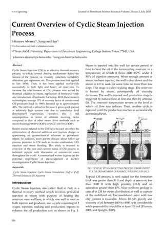
  • 1. www.jpsr.org Journal of Petroleum Science Research Volume 2 Issue 3, July 2013 Current Overview of Cyclic Steam Injection Process Johannes Alvarez*1, Sungyun Han*2 *Co-first authors are listed in alphabetical order. 1,2 Texas A&M University, Department of Petroleum Engineering, College Station, Texas, 77843, USA 1 johannes.alvarez@pe.tamu.edu; 2sungyun.han@pe.tamu.edu Abstract Cyclic Steam Injection (CSI) is an effective thermal recovery process, in which, several driving mechanisms define the success of the process; i.e. viscosity reduction, wettability alteration, gas expansion, etc. This process was first applied in late 1950s. Then, it has been applied world‐wide successfully to both light and heavy oil reservoirs. To increase the effectiveness of CSI, process was varied by chemical addition to steam, application of horizontal wells and introduction of hydraulic fracturing. With these modern technologies, average 15% of recovery factor of conventional CSI producers back in 1980’s boosted up to approximately 40%. The method is attractive because it gives quick payout at relatively high success rate due to cumulative field development experiences. However, this is still uncompetitive in terms of ultimate recovery factor compared to that of other steam drive methods such as steam flooding (50‐60% OOIP) or SAGD (60‐70% OOIP). Recent studies related to the CSI have focused on either the optimization of chemical additives and fracture design or questioning on geomechanical solutions to poroelastic effects. In addition, most papers discuss about follow‐up process posterior to CSI such as in‐situ combustion, CO2 injection and steam flooding. This study is oriented to overview of the past and current status of CSI process in technical aspects with discussion of commercial cases throughout the world. A summarized review is given on the potential importance of encouragement of further investigation of Cyclic Steam Injection. Keywords Cyclic Steam Injection; Cyclic Steam Stimulation; Huff n’ Puff; Thermal Enhanced Oil Recovery Introduction Cyclic Steam Injection, also called Huff n’ Puff, is a thermal recovery method which involves periodical injection of steam with purpose of heating the reservoir near wellbore, in which, one well is used as both injector and producer, and a cycle consisting of 3 stages, injection, soaking and production, repeats to enhance the oil production rate as shown in Fig. 1. 116 Steam is injected into the well for certain period of time to heat the oil in the surrounding reservoir to a temperature at which it flows (200~300°C under 1 MPa of injection pressure). When enough amount of steam has been injected, the well is shut down and the steam is left to soak for some time no more than few days. This stage is called soaking stage. The reservoir is heated by steam, consequently oil viscosity decreases. The well is opened and production stage is triggered by natural flow at first and then by artificial lift. The reservoir temperature reverts to the level at which oil flow rate reduces. Then, another cycle is repeated until the production reaches an economically determined level. FIG. 1 CYCLIC STEAM INEJCTINO PROCESS (FROM UNITED STATES DEPARTMENT OF ENERGY, WASHINGTON DC.) Typical CSI process is well suited for the formation thickness greater than 30 ft and depth of reservoir less than 3000 ft with high porosity (>0.3) and oil saturation greater than 40%. Near‐wellbore geology is critical in CSI for steam distribution as well as capture of the mobilized oil. Unconsolidated sand with low clay content is favorable. Above 10 API gravity and viscosity of oil between 1000 to 4000 cp is considerable while permeability should be at least 100 md (Thomas, 2008; and Speight, 2007).
  • 2. Journal of Petroleum Science Research (JPSR) Volume 2 Issue 3, July 2013 www.jpsr.org 117 Underlying Technology CSI includes three stages; injection, soaking and production, which are repeated until the oil production turns uneconomic (Prats, 1985, and Thomas, 2008). Application of CSI, like other EOR methods, targets to reduce the formation residual oil saturation by several driving mechanisms: viscosity reduction, changes in wettability and thermal and solution gas expansion (Prats, 1978) which depend on reservoir rock and fluid properties. For instance, viscosity reduction can be explained by mobility ratio which is the ratio of effective permeability to viscosity. In addition, during CSI many chemical reactions occur which mainly form gaseous components such as carbon dioxide, hydrogen sulfide, and hydrogen during steam injection (Hongfu et al., 2002); and these reactions include decarboxylation of the crude, formation of H2S from sulfur in the crude, formation of H2, CO, CH4 and CO2 from reactions between water and crude and formation of CO2 by decomposition and reactions of carbonates minerals (Prats, 1985). The produced gases formed during the CSI create additional driving mechanism which can be named as gas drive. Also, these visbreaking reactions reduce the oil viscosity by increasing the oil mobility (Pahlavan et al., 1995, Hongfu et al., 2002, and Prats, 1985). Hongfu et al., in 2002 reported a reduction of heavy oil viscosity between 28 and 42% after CSI. Reservoir Properties Changes with CSI Every stimulation that is performed in the reservoir has consequences; introducing heat into the formation by CSI produces stress and deformation in oil sand formations. The resulting pore volume changes affect the reservoir permeability and consequently water mobility. Scott et al., in 1994, claimed that the volume and permeability changes are the results of three effects: change in the mean principal effective stress, change in the shear stress and change in temperature. The increase in temperature causes thermal expansion of the sand grains and sand structure. In addition, studies conducted in Cold Lake field in Canada concluded that, during steam injection, the increase of pore pressure decreases the effective confining stress and causes an unloading of the reservoir (Scott et al., 1994). In the Clearwater formation in Canada, the effects of the volumetric expansion, during CSI, were transferred to the reservoir surrounding and the surface (Walters et al., 2000). This is sometimes observed as small elevations of the surface near the well, usually in shallow reservoirs. In addition, Walters et al., 2002 explained pressure changes in an isolated aquifer overlying the Clearwater formation as the result of poroelastic effects during CSI. However, these geomechanical deformations and failure mechanisms produced by CSI give the initial injectivity required for steam injection and the drive energy needed for the oil production (Yuan et al., 2011). CSI, due to the injection of a hot fluid into the formation, causes shear dilation (Wong et al., 2001). Hence, the pore rock characteristics change by means of enlarging their volume. This increases permeability which affects directly steam and hydrocarbon movements in the reservoir. Wong et al.. developed a model that provided a quantitative estimation of the permeability changes caused by shear dilation. Yale et al. affirmed that the most significant impact of dilation due to CSI is an increase in the permeability to water. This increase of the pore space is caused dilatation and mobility of the injected fluid. Further, condensation of hot water from steam ahead of the steam front pressurized the reservoir (Yale et al., 2010). Moreover, CSI induced displacements in the reservoir due to dilation and the recovery of these original conditions during production operations is a point of supply of reservoir drive energy. Gronseth, in 1989, studied the distribution of the injected fluids during CSI in the Clearwater formation, and found that if the injection rates are faster than diffusion rates into the matrix, the reservoir volume increases to adjust the volume of the injected fluid. This volume increase is translated into a pressure increase. Later, during production, reservoir pressure reduces and effective stresses increases, so the reservoir contracts and a portion, but not the entire increased reservoir volume, is recovered (Gronseth, 1989). There are techniques used to monitor reservoir deformation. These measures are important to optimize production and design parameters such as well length, well spacing, injection rate, cycle time, among others. In CSI, inclinometers and tilt‐meters, based on surface deformation, are used to monitor steam migration and formation dilation (Du et al., 2005). However, tilt‐meters are more accurate than inclinometers by more than one order of magnitude (Dusseault et al., 2002).
  • 3. www.jpsr.org Journal of Petroleum Science Research Volume 2 Issue 3, July 2013 History: Commercial Cases CSI was first used fortuitously in Venezuela in 1959. By that time, one of the steam injector wells began to produce, after a blowout, in much better conditions than the surrounding production wells (Trebolle and Chalot, 1993). Since then, this method has been applied in many fields such as Bolivar Coastal and Santa Barbara in Venezuela (Valera et al., 1999), Cold Lake Oil Sands in Canada, Xinjiang and Liaohe in China (Liguo et al., 2012), Midway‐sunset in California (Jones et al., 1990), among other heavy oil fields. At the early stages of CSI application, CSI was considered as an old‐school oil production method in which operations are ahead of research developments (Ramey et al., 1969). The literature shows that many publications, explaining CSI processes, were based on field experiences rather than research work. There are a lot of unknowns about the process parameters such as the number of stimulation cycles, well orientation and number of wells, operating condition, the increase of water cut, among others. Therefore, on early CSI field applications, the process was performed as trial‐and‐ 118 error field‐scale experiment (Ramey, 1967). After many research studies and field experiences, important technology problems were reduced. First, the number of stimulation cycles increased by time. By 1974, CSI has an average of three stimulation cycles with a maximum reported of 22 (Ali et al., 1974). In 1990, in the Midway‐Sunset field, California, there was already a well with 39 cycles. Also, out of 1500 wells, there were 75 wells with more than 30 cycles, and 350 wells with more than 20 cycles (Jones et al., 1990). This increment in the number of cycles was accomplished by getting better understanding of steam properties, reservoir characteristics, and injection conditions. Second, well orientation and number of wells were improving by time. In Trinidad and Tobago, slim‐hole injectors, insulated tubing and packers, and limited entry perforations have been used to combat gravity segregation consequences (Khan, 1992). As well, steam was injected with foam‐diverting agents to control water breakthrough resulting from high injectivity. In addition, in the Cold Lake oil sands, Canada, steam distribution in horizontal wells was improved by using screen sections, which facilitated contact between the well and the reservoir. Also, inside these screen sections, small flow orifices were used to control the flow between the inner pipe and the reservoir to enhance oil production and reduce steam consumption (Oil and Gas Journal report by Bob Tippee, 2012). In China, the most up to date methods and techniques used in CSI include: high‐efficient steam injection by automatic controlling steam generation, insulating surface pipeline and multi‐zone steam injection; as well as artificial lifting, sand control, CSI with chemical additives, re‐entry drilling technology, and process control systems (Haiyan et al., 2005). In addition, steam distribution has been improved by using separated‐zone steam injection techniques such as selected, dual and multi zone injection, either sequentially or simultaneously. This method showed, in field testing to 76 wells of the Liaohe oil field, an increase up to 70% of the steam zone (Liguo et al., 2012). Moreover, as well in horizontal well, the tubing and annulus of the same well have been applied to inject to in the toe and heel separately (Liguo et al., 2012). Third, operating conditions of pressure and temperature have adjusted to each case based on reservoir properties and well design. In the Cold Lake field, CSI has been achieved by injection at pressures high enough to fracture the formation (Beattie et al., 1991). In California, specifically in Potter sands in the Midway‐Sunset field, a sequential steaming process was implemented. This approach involved heating the reservoir rather than heating each well separately (Jones et al., 1990). The wells were stimulated in rows from down to up dip of the reservoir. Using this methodology, the production per well increased up to a rate of 30% per year (Jones et al., 1990). Another technique, in pilot stage and successfully simulated, is the use of Top‐Injection Bottom‐ Production (TINBOP) whose principle is to inject steam at the top of the reservoir using the short well string and produced from the bottom of the reservoir using the long well string. (Morlot et al., 2007). Simulation studies, conducted by Morlot et al. showed TINBOP increased oil recovery by 57 to 93%, compared to conventional CSI (Morlot et al., 2007). One feature of this method is that there is no soaking period. Fourth, the increase of water cut is also addressed. In CSI, each succeeding cycle normally increases water cuts (Ali et al., 1974). Consequently, in the late 70’s there was a trend to convert these operations into
  • 4. Journal of Petroleum Science Research (JPSR) Volume 2 Issue 3, July 2013 www.jpsr.org 119 steam drives due to the decrement in oil recovery (Prats, 1978). This trend has changed in the last years with the use of chemical additives on CSI. Recently, there have been important progresses in oil recovery using chemical addition. Although CSI increases oil recovery, chemical addition with CSI increases it even further (Ramey et al., 1967). Nowadays, in CSI processes, co‐injection of steam with gels, foams, and surfactants, among other chemicals, are used to increase oil production and reduce water production. In Russia, specifically in the Permian‐Carboniferous reservoirs of the Usinsk field, gels and foams have been injected with CSI from 2007 to 2011, and an increase of 20‐30% oil rate and decreased 33‐35% water cut (Taraskin et al., 2012) have been observed. In Canada, Liquid Addition to Steam for Enhancing Recovery (LASER) has been field‐tested for a single cycle at Cold Lake field. Previous work indicated that, if successful, the LASER process could increase the recovery factor by 3 – 6% OOIP (Leaute et al., 2007). Similarly in Canada, other processes have been tested to increase CSI performance such as air injection, achieving 15% incremental in addition to the 12‐20% recovery with high pressure CSI (Jiang et al., 2010), and biodiesel and carbamide injection (Babadagli et al., 2010 and Zhang et al., 2009), both used as surfactants to enhance the CSI efficiency. The field tests in Henan Oil Field, China, using carbamide increased oil recovery by 7% and decreased Residual Oil Saturation (SOR) almost by 1% (Zhang et al., 2009). As well, in the Bachaquero field in Venezuela, an ionic‐alkyl‐aryl sulfonate surfactant (LAAS) has been used to generate foams that enhance steam distribution more evenly in the reservoir by restricting steam to the areas with higher permeability. This technique has improved the production per cycle from 15 to 40% (Valera et al., 1999). Moreover, solvents have been used to improve steam injectivity by removing organic deposits from the rock and changing its wettability in Costa Bolivar, Zulia, Venezuela (Mendez et al., 1992). Finally, wettability changes in CSI due to temperature increase have been studied by several authors with different results. On one hand, there is a line of thought which assures that as temperature increases, the system oil‐water‐rock becomes more water‐wet (Prats, 1985, Schembre et al., 2006, Kovscek et al., 2008, and Poston et al., 1970). On the other hand, another tendency advocates that the system becomes more oil‐wet as temperature increases (Rao and Karyampudi, 1999, Escrochi et al., 2008, and Rao, 1999); also, there is a third line of thought explaining that wettability is independent of temperature changes (Miller and Ramey, 1985, and Pollkar et al., 1989). Studies with Diatomaceous rocks and Berea sandstones conducted by Schembre et al., 2006, showed that both diatomaceous and Berea cores become more water‐wet as temperature increases (from 100 to 200°C). This behavior was attributed to fines detachment, in low salinity and high pH steam condensate fluid, which stabilizes a thin water film that covers the rock surface avoiding contact with the oil phase. This fines detachment depends on temperature and mineralogy; for example, wettability changes are reached faster in silica than that in clays (Schembre et al., 2006). In addition, Poston et al., 1970, conducted similar studies using unconsolidated sands from Houston sands and Midway‐Sunset field, California, reaching the conclusion that increasing temperature (from 25 to 150°C) is determined in improving water‐wetness in the unconsolidated sands. On the other hand, Rao and Karyampudi, 1999, and Rao, 1999, conducted CSI lab and field test in the heavy oil and bitumen Elk Point Cummings formation, Canada. Their results showed that at high temperatures (162 to 196–°C), the formation, which is mainly silica (87%), became oil‐wet. Moreover, they also discover that salt deposition, mainly calcium carbonate (CaCO3), in one of the core layers prevented oil‐wet behavior at high temperatures, changing the wettability to water‐wet. This effect was proved in core flooding and field test in which increment in oil rate and decrement in water cut were observed (from 22 BPD and 83% in the fourth cycle to 51 BPD and 77% in the five cycle) (Rao and Karyampudi, 1999). Wettability reversal effect at high temperatures is also attributed to asphaltene precipitation. Using Athabasca bitumen and live oil sample with 5% and 3.17% asphaltene respectively, Escrochi et al., 2008, showed that from 150 to 400 °C the system shifted to oil‐wet until asphaltene precipitation was completed and then wettability was changed to water‐wet. Moreover, in the literature, results showed that temperature do not impact wettability during CSI, and Miller and Ramey, 1985 tested the unconsolidated Ottawa Silica Sand and a consolidated Berea Sandstone with temperatures from 25 to 150° C, concluding that there were not changes in residual
  • 5. www.jpsr.org Journal of Petroleum Science Research Volume 2 Issue 3, July 2013 saturations that imply variance in wettability. The same results were reached in the unconsolidated silica sands at 125 to 175 °C by Pollkar et al., 1989. Consequently, when CSI is applied, there are different positions in describing wettability mechanism and their changes with temperature. However, it is important to point out that these results mainly depend on the chemical properties of fluids injected, asphaltene content and the mineralogy of the reservoir. From its early stages until today, CSI has evolved significantly from a process discovered by chance where trial and error governed the operations with little number of cycles and low recovery factor to state‐of‐the‐art applications with a great variety of chemical additives and well geometries which increase the number of cycles and the ultimate oil recovery. However, more research needs to be done in evaluating wettability changes at field scale to determine the factors that influence early water break and reduce oil production at different mineralogy and injection temperatures. Current State-of-the-art: Applications The method is quite effective, especially in the first few cycles providing quick payout. However, ultimate recovery by cyclic steam injection is low (10‐40% of Original Oil in Place, OOIP), compared to that of steam flooding and Steam Assisted Gravity Drainage (SAGD) which are over 50% of OOIP (Thomas, 2008; Speight, 2007; Xia and Greaves, 2006) as shown in TABLE. 1. Therefore, it is quite common for wells to be produced in the cyclic steam manner for a few cycles before put on a steam flooding regime with other wells (Alikhlalov et al., 2011). TABLE 1 OIL RECOVERY RATE OF THERMAL EOR METHODS 120 Oil Recovery Factors (successful projects) Thermal EOR % of OOIP CSI 10 ‐ 40 Steam flooding 50 ‐ 60 SAGD 60 ‐ 70 In‐situ Combustion* 70 ‐ 80 *In‐situ Combustion using THAI—‘Toe‐to‐Heel Air Injection’ Conventional CSI process usually has average recovery factor lower than 20%. However, this can be doubled with combination of unconventional technologies which have become profitable including co‐injection of steam with chemical additives, directional drilling, and hydraulic fracturing. Recently, technical aspects like injected steam/produced oil ratio, presence of water cut in the producing well and excessive heat losses have required special attention. Many literatures have presented studies on these areas at laboratory scale (i.e, Castro et al., 2010). Investigations have been optimizing the cyclic steam injection technology by chemical addition to the steam. Currently, the performance of CSI is enhanced by co‐injection of steam with chemicals such as surfactants, solvents, miscible and immiscible gases. CSI with Chemical Additives Since 1960, investigations on cyclic steam injection technology have been conducted to improve recovery factor by adding chemical additives to steam, fracturing, and placing horizontal wells for different types of reservoir. In the reservoir, the chemical additives enhance the production by increasing the mobility of oil and enabling condensed water to carry higher loading of oil. Numerous studies on chemical additives to steam have been conducted to affect heavy oil properties favorably such as solvents, surfactants, miscible and immiscible gases. 1) Solvents The idea of adding solvents to the steam to reduce the oil viscosity has been reported in the literature since 1970s. Previously, solvents and light crudes had been used as diluents to optimize pumping and pipeline transportation of heavy crudes. Both laboratory and field tests later years proved that the use of solvent as an additive to steam during in‐situ recovery improved the mobility ratio of displacing and displaced fluid and sweep efficiency. The mechanism is following: the vaporized solvent is co‐injected with steam and travels with the steam front. It condenses and mixes with the oil in the cooler regions of reservoir creating a transition zone of lower‐viscosity fluid between steam and oil. Consequently, the mobility ratio between steam and oil increases, resulting in higher production rate. The success of process depends on the solvent type, treatment size and the solvent placement. It was concluded that the use of small quantities of medium volatile solvent (no more than 10% of steam volume) creates the best effectiveness in increasing total oil production (Shu and Hartman, 1988). In many of the previous researches, naphtha
  • 6. Journal of Petroleum Science Research (JPSR) Volume 2 Issue 3, July 2013 www.jpsr.org 121 was employed quite frequently which was found to be highly effective in opening a steam flow path due to its high volatility. Other solvents that were used in recent researches include CO2, ethane, and a mixture of gases (Yongtao et al., 2011), kerosene, and even some effluents from some refinery processes (Castro et al., 2010). 2) Surfactants Although adding solvents to steam can increase production recovery up to 30% upon earlier cycles, high injection volumes are required to reduce the viscosity of oil appreciably thereby necessitating solvent recovery, which leads to high operational costs. Therefore, adding surfactants to injected steam to reduce oil‐water interfacial tension and alter wettability and therefore increase recovery was introduced. Most widely used agent is called Thin Film Spreading Agents (TFSA). TFSA compounds reduce interfacial tension by the application of a spreading film strong enough to overcome the emulsifying agents naturally found between the oil‐water and oil‐rock interfaces. By reduction of the interfacial energies between the oil‐rock and water‐rock, water wetting of the rock results, leading to the release of oil particles from the rock surface improving oil mobility (Adkins et al., 1983). Successful field applications of TFSA in California and Alberta were reported with indication of significant improvement in heavy oil recovery factor up to 20% (Srivastava and Castro, 2011). The capability of the steam‐surfactant mixture to divert steam entry into the sands varies directly with the concentration of the surfactant present, steam quality and the addition of a non‐condensable gas. Some pilot tests in Bolivar Coast, Venezuela, reported the optimum level of surfactant concentration in the steam liquid phase 1 to 1.3 % (Robaina et al., 1988) above which no additional diversion was obtained. Most conventional surfactant injection projects, steam quality maintained averagely 60 to 70% (Blair et al 1982; Adkins et al., 1983). Co‐injections of more efficient surfactants were also tested; however, they required high steam quality as 80 to 90%, which causes higher operating costs. Srivastava and Castro reported that TFSA requires only small amount of concentration (250 ppm) while sustaining steam quality as below 70% (Srivastava and Castro, 2011). Additionally, some laboratory tests demonstrated that introducing non‐condensable gases (i.e nitrogen) helps to stabilize the foam, affording greater plugging of the porous media consequently (Robaina et al., 1988). CSI with Horizontal Well Due to the presence of certain sand volumes at the bottom of the reservoir which is not recoverable by using vertical wells, the idea of horizontal well was introduced to the CSI process. The main advantages of the horizontal wells are improved sweep efficiency, increased producible reserves as well as steam injectivity, and decreased number of well required for field development (Joshi, 1991). Although most of simulation studies proved notable advantages of horizontal well over vertical well (Adegbesan 1992, and Chang et al., 2009), CSI with horizontal well had little success in fields before 2000s. The main reason was the extra operating costs which were double that of vertical wells back then. Other factors include geological/reservoir characteristics and operational aspects such as uneven steam distribution and sand productions. For example, the activity of horizontal drilling in Bachaquero field in Venezuela where high oil viscosity (~18000 cp) encountered did not appear profitable, causing a low annular fluid level (Mendoza et al., 1997). A simulation study later on also showed that the application of horizontal well in same field was not economically attractive (Escobar et al., 2000). On the other hand, few pilot tests in early 2000s had success on horizontal well application; and indeed, those horizontal producers in comparison to typical vertical ones in each area improved production performance and thermal efficiency as well as operating costs. Representative pilots are in South Midway‐Sunset field (McKay et al., 2003) and Cymric/McKittric field in California (Cline et al., 2002). Both fields showed about 20 to 50% improvement in production over results from vertical wells and benefited from maximum 45% of directional drilling cost reduction relative to that of a decade ago. Despite the reduced drilling costs, operating costs for generating steam still remains high due to greater heat loss when steam injection is schemed to horizontal well application. Further investigations inquire possibilities to address the solutions to this problem. Chang et al., examined in his simulation study the co‐injection with solvent (n‐hexane C6H14) and alternate solvent/steam cycles to reduce total number of cycles. (Chang et al,. 2009).
  • 7. www.jpsr.org Journal of Petroleum Science Research Volume 2 Issue 3, July 2013 CSI with Hydraulic Fracturing The idea of combining cyclic steam stimulation with hydraulic fracturing came out when both steam injection and completion (i.e, sand control completion) techniques generated potential formation damage thus, the permeability near the wellbore creating a choke was lowered that further reduces the oil mobility. Creating fractures allows a more efficient placement of injected steam, heating up larger volume of reservoir and reducing residual oil saturation. This combination is usually considered for low‐permeability 122 heavy oil reservoirs like California diatomite (0.1‐0.5 md) or Athabasca oil sands (~2.5 d). Several studies reported desirable results (Manrique et al., 1996, and Settari et al., 1981). Fines and sand production problems are found commonly during cyclic steam injection. The recent study investigated the efficiency of fracturing with viscoelastic surfactant fluid instead of water which worsens the sand and fine production. It was concluded that anionic surfactant fluids minimize gel damage and maintain favourable proppant transportation (Gomez et al., 2012). Follow Up Methods: Post CSI CSI is widely used in oil recovery due to its quick response; however, recovery factors are relatively low (10‐40% OOIP) compared to other thermal methods such as steam flooding (50‐60% OOIP) or in‐situ combustion (70‐80% OOIP) (Thomas, 2008). This is because the natural energy of the reservoir, as well as oil production, decreases and, when several cycles are reached, oil production tends to decrease even more with decreasing pressure and increasing water production. Consequently, some follow‐up processes are used after the implementation of CSI to improve oil recovery, such as CO2 injection (Luo et al., 2005), steam flooding (Yang, 2007), and air injection as in‐situ combustion (Gates et al., 2011, and Hajdo et al., 1985), among others. One example of CO2 injection after CSI is in the Lengjiabao heavy oil reservoir, in which CO2 was injected in extra heavy oil (10,000 ‐50,000 mPa.s at 50°C) after 3 cycles of CSI with satisfactory results; increasing oil mobility with CO2 utilization ratio from 3.0 to 6.0 tons oil /tons CO2 and oil recovery from 10 to 35% (Luo et al., 2005). However, in other wells tested with low permeability, porosity and oil saturation, the injection of CO2 did not increase oil production. Another thermal method frequently used as a follow up process for CSI is steam flooding. One of the experiences reported was in the Guantao formation (porosity and permeability relatively high and extra heavy oil with viscosities of 230,000 mPa∙s at 50°C) in the Liaohe Oil Field, China, where CSI was applied previously. Steam flooding was adapted by using horizontal wells placed between current vertical CSI wells (Yang, 2007). These vertical wells produced for 3 cycles by CSI and then some of them were switched to steam flood as soon as the horizontal‐vertical wells communication was identified. Yang in 2007 reported that the wells have been producing since February 2005 by steam flooding favored by gravity drainage forces. Initially, the predicted oil recovery by CSI was 29% of OOIP, and, with steam flooding follow up after CSS, the forecasted oil recovery was 56% (Yang, 2007). However, steam flooding is not the right recipe as follow‐up after CSI for all types of formations. Every reservoir has its own characteristics such as vertical and horizontal permeabilities, reservoir properties changes caused by CSI, reservoir thickness, and viscosity of the fluids, among others, which have to be evaluated before steam flooding is implemented after CSI (He et al., 1995). In the Bachaquero‐01 reservoir in western Venezuela, CSI has been used since 1965 and currently the production wells have more than 6 cycles. An Extended Cyclic Steam Injection, which is a combination of steam injection and steam flooding, was evaluated numerically. The prediction cases were simulated for 7 cycles of 14 months each and approximately 9 months of steam flooding in different well patters (Chourio et al., 2011). The simulated results showed that there was an additional recovery of 3.7%, reaching the highest recovery in the area of 24.3% of OOIP (Chourio et al., 2011). The pilot test for this project was planned in 2012. Finally, in‐situ combustion performance has also been numerically investigated as a follow up process for CSI (Gates et al., 2011). In Canada, in the Margarite Lake, in wells with a depth of 1476 feet and thickness of 112 feet (Hajdo et al., 1985) and Morgan Field, with wells with a depth of 670 feet and thickness of 30 feet (Marjerrison and Fassihi, 1995), air injection pilots were performed after CSI and the process were proved to be successful (Gates et al., 2011, Hajdo et al., 1985 and Marjerrison and Fassihi, 1995). In addition, CSI was implemented in the Cold Lake oil sands, and the oil recovery was recorded to be 15‐20% of the
  • 8. Journal of Petroleum Science Research (JPSR) Volume 2 Issue 3, July 2013 www.jpsr.org 123 OOIP (Nzekwu et al., 1990). Consequently, an in‐situ combustion process was implemented. The results, presented by Nzekwu et al. showed that the average reservoir temperature and heated zone increased after in‐situ combustion which consequently would increase oil recovery. In addition, in the heavy oil reservoir of Midway Field in California, a successful in‐situ combustion pilot was conducted in a section subjected to CSI for seven years (Counihan, 1977). The previous CSI cycles helped injectors to prevent burnout, clean the perforations and reduce spontaneous ignition. Currently, the most used follow up process after CSI is steam flooding. One reason is because it utilizes the installed equipment into the well and on surface which reduces capital cost. However, the most important ground is due to its attribute to sweep the remaining oil to a specific production well. Moreover, CO2 flooding has been proved to be successful in limited areas and further research must be done to fully develop this technique; likewise, initial investment and CO2 utilization affects directly capital cost. Finally, air injection has been efficient in some places as well, but it is a process very complicated for simulation and field tested. Conclusions - CSI has improved since its discovery in 1959, little number of cycles and low recovery factor have been increased by the use of chemical additives and by better understanding of the geometry and mineralogy of the wells. However, more research needs to be done in understanding relative permeability and wettability changes with temperature at field scale in different formations to increase ultimate oil recovery. - Cyclic Steam Injection combined with unconventional technologies such as co‐injection with chemical additives, horizontal drilling and hydraulic fracturing have been highly successful, improving its conventional recovery factor up to 40%. Recent studies showed that this can be increased even higher. - Cyclic Steam Injection with horizontal well has had considerable success thanks to reduced directional drilling cost and improved sweep efficiency, although further economic evaluations need to be considered. - CSI with Hydraulic fracturing has shown good results for low‐permeability formation. Further investigation on fracturing fluid needs to be acquired to solve sand productions during the operation. - In many cases, follow up processes after CSI are convenient solutions to increase reservoir ultimate recovery. However, these processes must be evaluated carefully considering reservoir properties and mineralogy and fluid interaction before fully implemented. In addition, in follow up process selection, economic viability is a major issue, so the increase in oil recovery must be sufficient to cover capital cost and maintain the project profitable during the forecasted time. ACKNOWLEDGMENT The authors would like to thank Dr. Berna Hascakir for her guidance and encouragement to write this paper. REFERENCES Adegbesan, K. G. (1992). “Reservoir Simulation Study of a Thermal Horizontal Well Pilot in the Cold Lake Oil Sands.” SPE Reservoir Engineering 7(4): 403‐406. Adkins, J. D. (1983). “Field Results of Adding Surfactant to Cyclic Steam Wells.” SPE Annual Technical Conference and Exhibition. San Francisco, California, Society of Petroleum Engineers. Ahmed, Tarek, D., Meehan, and Nathan. (2012). “Advanced Reservoir Management and Engineering (Second Edition).” Pages 541‐585. Ali, Farouq S. M. (1974). “Current Status of Steam Injection as a Heavy Oil Recovery Method.” Journal of Canadian Petroleum Technology. Volume 13, Number 1. Alikhlalov, K. and Dindoruk B. (2011). “Conversion of Cyclic Steam Injection to Continous Steam Injection.” SPE Annual Technical Conference and Exhibition. Denver, Colorado, USA, Society of Petroleum Engineers. Babadagli, T., Er, V., Naderi, K., Burkus, Z., and Ozum, B. (2010). “Use of Biodiesel as an Additive in Thermal Recovery of Heavy Oil and Bitumen.” Journal of Canadian Petroleum Technology. Volume 49, Number 11. Beattie, C.I., Boberg, T.C., and McNab, G.S. (1991). “Reservoir Simulation of Cyclic Steam Stimulation in the Cold Lake Oil Sands.” SPE Reservoir Engineering. Volume 6, Number 2.
  • 9. www.jpsr.org Journal of Petroleum Science Research Volume 2 Issue 3, July 2013 Blair Jr., C. M., Scribner, R. E., and Stout, C. A. (1982). 124 “Chemical Enhancement of Oil Production by Cyclic Steam Injection.” Journal of Petroleum Technology 34 (12): 2757‐2762. Castro, Y. E., Veliz, A. M., Sanchez, D. A., Rodriguez, M. M., Rondon, N. G., Rivero, S., and Cortez, M.L. (2010). “Cyclic Steam Injection with Solvents as Method of Thermal Recovery for Heavy and Extraheavy Oils: Laboratory Tests.” Canadian Unconventional Resources and International Petroleum Conference. Calgary, Alberta, Canada, Society of Petroleum Engineers. Chang, J., Ivory, J., and Rajan, R. S. V. (2009). “Cyclic Steam‐ Solvent Stimulation Using Horizontal Wells.” Canadian International Petroleum Conference. Calgary, Alberta, Petroleum Society of Canada. Chourio, Geragg; Bracho, Jose and Mohtad, Mehrdad. (2011). “Evaluation and Application of the Extended Cyclic Steam Injection as a New Concept for Bachaquero‐01 Reservoir in West Venezuela.” SPE 148083‐MS. Cline, V. J. and M. Basham. (2002). “Improving Project Performance in a Heavy Oil Horizontal Well Project in the San Joaquin Valley, California.” SPE International Thermal Operations and Heavy Oil Symposium and International Horizontal Well Technology Conference. Calgary, Alberta, Canada. Counihan, and Thomas M. A. (1977). “Successful In‐Situ Combustion Pilot in the Midway‐Sunset Field, California.” SPE 6525‐MS. Du, J., Brissenden, S.J., McGillivray, P., Bourne, S., Hofstra, P., and Davis, E.J., Roadarmel, W.H., Wolhart, S.L., Marsic, S., Gusek, and R., Wright, C.A. (2005). “Mapping Reservoir Volume Changes During Cyclic Steam Stimulation Using Tiltmeter Based Surface Deformation Measurements.” SPE 97848‐MS. Dusseault, M.B. and Rothenburg, L. (2002). “Analysis of Deformation Measurements for Reservoir Management.” Oil & Gas Science and Technology – Rev. IFP, Vol. 57. No. 5, pp. 539‐554. Escobar, E., Valko, P., Lee, W. J., and Rodriguez, M.G. (2000). “Optimization Methodology for Cyclic Steam Injection with Horizontal Wells.” SPE/CIM International Conference on Horizontal Well Technology. Calgary, Alberta, Canada. Escrochi, M., Nabipour, M., Ayatollahi, Sh., and Mehranbod, N. (2008). “Wettability Alteration at Elevated Temperatures: The Consequenses of Asphaltene Precipitation.” 2008 SPE Internatiomal Symposium and Exibitionon Formation Damage held in Lafayette, Luisiana, USA. SPE 112428. Gates, Ian D. and Wang, Jacky. (2011). “Evolution of In Situ Oil Sands Recovery Technology in the Field: What Happened and Whatʹs New?” SPE 150686‐MS. Gomez, J., Morales, H., Toyo, D., and Bracho, J. (2012). “Fracturing With Viscoelastic Surfactant Fluid in Cyclic Steam Injection Wells ‐ A Synergy for Heavy Oil Recovery.” SPE 153536‐MS. Gronseth, J.M. (1989). “Geomechanics Monitoring of Cyclic Steam Stimulation Operations In the Clearwater Formation.” International Society for Rock Mechanics IS‐1989‐166. Haiyan, H., Shuhong, W., Yitang, Z., Dingmin, W., and Zhong, G. (2005). “State‐of‐the‐Art of Heavy‐Oil Development in China and Its Technology Challenges.” SPE 10617‐MS. Hajdo, L.E., Hallam, R.J., and Vorndran. (1985). “Hydrogen Generation During In‐Situ Combustion.” SPE 13661‐MS. He, Z., Zhang, R., Pu, H. Y., and Ren, X. (1995). “The Feasible Conditions Study of Steamflooding for Heavy Oil Reservoirs In China After Cyclic Steam Injection.” SPE 30303‐MS. Hongfu, F., Yongjian, L., Liying, S., and Xiaofei, Z. (2002). “The Study on Composition Changes of Heavy oils during Steam Stimulation Processes.” ELSEVIER. Fuel 81. p.p 1733‐1738 . Jiang, Q., Thornton, B., Russel‐Houston, J., and Spence, S. (2010). “Review of Thermal Recovery Technologies for the Clearwater and Lower Grand Rapids Formations in the Cold Lake Area in Alberta.” Journal of Canadian Petroleum Technology. Volume 49, Number 9. Jones, Jeff and Cawthon, Gary J. (1990). “Sequential Steam: An Engineered Cyclic Steaming Method.” Journal of Petroleum Technology. Volume 42, Number 7. Joshi, S. D. (1991). “Thermal Oil Recovery With Horizontal Wells (includes associated papers 24403 and 24957).” Journal of Petroleum Technology 43(11): 1302‐1304.
  • 10. Journal of Petroleum Science Research (JPSR) Volume 2 Issue 3, July 2013 www.jpsr.org 125 Khan, Jamaludin and Parag, Dhanpaul. (1992). “Twenty‐ Five Years of Oil Recovery by Steam Injection.” SPE 24198‐MS. Kovscek, A.R., Schembre,, J.M. and Tang, G.‐Q. (2008). “Authors’ Reply to Discussion of Interrelationship of Temperature and Wettability on the Relative Permeability of Heavy Oil in Diatomaceous Rocks.” SPE Reservoir Evaluation & Engineering. Volume 11, Number 3. p.p. 437‐438. Leaute, R. P. and Carey, B. S. (2007). “Liquid Addition to Steam for Enhancing Recovery (LASER) of Bitumen with CSS: Results from the First Pilot Cycle.” Journal of Canadian Petroleum Technology. Volume 46, Number 9. Liguo, Zhong; Shoujun, Zhang; Fei, Wu; Baoshan, Lang; Heng, Liu and Shuai, Gai. (2012). “Improved Heavy‐Oil Recovery by Separated‐Zones Horizontal‐Well Steam Stimulation.” Journal of Canadian Petroleum Technology. Volume 51, Number 2. Luo, R., Cheng, L.‐S., and Peng, J.‐C. (2005). “Feasibility Study of CO2 Injection for Heavy Oil Reservoir after Cyclic Steam Stimulation: Liaohe oilfield test.” SPE 97462‐MS. Manrique, J. F. (1996). “Optimization of Thermal Processes Through Combined Application of Horizontal Wells and Hydraulic Fracturing Technology.” International Conference on Horizontal Well Technology. Calgary, Alberta, Canada, Society of Petroleum Engineers, Inc. Marjerrison, D.M. and Fassihi, M.R. (1995). “Morgan pressure cycling in‐situ combustion project: performance and modeling.” Geological Society, London, Special Publications. V.84. p. 275‐286. McKay, C., Jones, J., Pomerene, J. (2003). “Successful Horizontal Producers in Midway‐Sunset Thermal Operations.” SPE Western Regional/AAPG Pacific Section Joint Meeting. Long Beach, California, Society of Petroleum Engineers. Mendez, Z., Alvarez, J. M., Escobar, E., Colonomos, P., and Campos, P. (1992). “Cyclic Steam Injection With Additives: Laboratory and Field Test Results of Steam/Foam and Steam/Solvent Processes.” SPE Annual Technical Conference and Exhibition. Washington, D.C. Society of Petroleum Engineers Inc. SPE 24632‐MS Mendoza, H., Padron, A., and Portillo, F. (1997). “Steam Stimulation In Horizontal Wells Pilot Test In Venezuela.” Annual Technical Meeting. Calgary, Alberta, Petroleum Society of Canada. Miller, Mark A., and Ramey Jr., H.J. (1985). “Effect of Temperature on Oil/Water Relative Permeabilities of Unconsolidated and Consolidated Sands.” SPE Journal. Volume 25, Number 6. p.p. 945‐953. Morlot, C. D. and Mamora, D. (2007). “TINBOP Cyclic Steam Injection Enhances Oil Recovery in Mature Steamfloods.” Petroleum Society of Canada. Nzekwu, Ben I., Hallam, Richard J., and Williams, G.J.J. (1990). “Interpretation of Temperature Observations From a Cyclic‐Steam/ In‐Situ‐Combustion Project.” SPE Reservoir Engineering. Volume 5, Number 2. Oil and Gas Journal by Bob Tippee. (2012). “ExxonMobil licenses oil sands steam system.” Houston, Feb. 2, 2012. http://www.ogj.com/content/ogj/en/articles/2012/02/exx onmobil‐licenses‐oil‐sands‐steam‐system.html. Pahlavan, Hamid and Rafiqul, Islam. (1995). “Laboratory simulation of geochemical changes of heavy crude oils during thermal oil recovery.” Journal of Petroleum Science and Engineering. Volume 12, Issue 3, Pages 219–231. Pollkar, Marcel, Puttagunta, V. R., Decastro, V., Ali, and Farouq S. M.. (1989). “Relative Permeability Curves For Bitumen And Water In Oil Sand Systems.” Journal of Canadian Petroleum Technology. Volume 28, Number 1. Poston, S.W., Ysrael, SHossain, A.K.M.S., Montgomery III, E.F., and Ramey Jr., H.J. (1970). “The Effect of Temperature on Irreducible Water Saturation and Relative Permeability of Unconsolidated Sands.” SPE Journal. Volume 10, Number 2. p.p. 171‐180. Prats, Michael. (1978). “A Current Appraisal of Thermal Recovery.” Journal of Petroleum Technology. Volume 30, Number 8. Prats, Michael. (1985). “Thermal Recovery.” SPE Monograph Volume 7. Chapter 6. 1985. Ramey Jr., H. J. A. (1967). “Current Review of Oil Recovery by Steam Injection.” SPE 12247. Ramey Jr., Henry J. (1969). “A Current Look at Thermal Recovery.” SPE 2739‐MS.
  • 11. www.jpsr.org Journal of Petroleum Science Research Volume 2 Issue 3, July 2013 Rao, Dandina N. (1999). “Wettability Effects in Thermal 126 Recovery Operations.” SPE Reservoir Eval. & Eng. Vol. 2, No. 5. Rao, Dandina N., and Karyampudi, R.S. (1999). “Productivity Enhancing Wettability Control Technology for Cicluc Steam Process in the Elk Point Cummings Formation. “ Journal of Canadian Petroleum Technology. Special Edition 1999, Volume 38, Number 13. Reis, J. C. (1990). “Studies of Fractures Induced During Cyclic Steam Injection.” SPE California Regional Meeting. Ventura, California, Society of Petroleum Engineers Inc. Robaina, R. M. and J. L. Ziritt (1988). “Evaluation of a Surfactant: Steam‐Soak Pilot Test in the Bolivar Coast, Venezuela.” SPE Enhanced Oil Recovery Symposium. Tulsa, Oklahoma, 1988. Schembre, J.M., Tang, G.‐Q., and Kovscek, A.R. (2006). “Interrelationship of Temperature and Wettability on the Relative Permeability of Heavy Oil in Diatomaceous Rocks (includes associated discussion and reply).” SPE Reservoir Evaluation & Engineering. Volume 9, Number 3. p.p. 239‐250. Scott, J. D., S. Proskin, A., and Adhikary, D. P. (1994). “Volume And Permeability Changes Associated With Steam Stimulation In an Oil Sands Reservoir.” Journal of Canadian Petroleum Technology. Volume 33, Number 7. Settari, A. and J. M. Raisbeck. (1981). “Analysis and Numerical Modeling of Hydraulic Fracturing During Cyclic Steam Stimulation in Oil Sands.” Journal of Petroleum Technology 33 (11): 2201‐2212. Shu, W. R. and K. J. Hartman. (1988). “Effect of Solvent on Steam Recovery of Heavy Oil.” SPE Reservoir Engineering 3(2): 457‐465. Speight, J. G. (2007). “The Chemistry and Technology of Petroleum.” CRC Press/Taylor & Francis. 4th Edition, Volume 114, Chapter 6. Srivastava, P. and Castro, L. U. (2011). “Successful Field Application of Surfactant Additives to Enhance Thermal Recovery of Heavy Oil.” SPE Middle East Oil and Gas Show and Conference. Manama, Bahrain, Society of Petroleum Engineers. Taraskin, Evgeniy; Ursegov, Stanislav; Pechor, N., Muliak, Vladimir; Chertenkov, Mikhail, and Alabushin, Andrey. (2012). “Thirty Years of Experience in the Application of Thermal Methods of Heavy Oil Recovery in the Permian‐Carboniferous Reservoir of the Usinsk Field.” SPE 160759‐MS. Thomas, S. (2008). “Enhanced Oil Recovery – An Overview.” Oil & Gas Science and Technology – Rev. IFP, Vol. 63. No. 1, pp. 9‐19. Trebolle, R. L., Chalot, J. P., and Colmenares, R. (1993). “The Orinoco Heavy‐Oil Belt Pilot Projects and Development Strategy.” SPE International Thermal Operations Symposium. Bakersfield, California, Society of Petroleum Engineers, Inc. Valera, Cesar A., Escobar, Manuel A., and Iturbe, Yrene J. (1999). “Use of Surfactants in Cyclic Steam Injection in Bachaquero‐01 Reservoir.” SPE 54020‐MS. Walters, D.A., Settari, A., and Kry, P.R. (2000). “Poroelastic Effects of Cyclic Steam Stimulation in the Cold Lake Reservoir.” SPE 62590‐MS. Walters, D.A., Settari, A., and Kry, P.R. (2002). “Coupled Geomechanical and Reservoir Modeling Investigating Poroelastic Effects of Cyclic Steam Stimulation in the Cold Lake Reservoir.” SPE Reservoir Evaluation & Engineering. Volume 5, Number 6. Wong, R. C. K. and Li, Y. (2001). “A Deformation‐ Dependent Model for Permeability Changes in Oil Sand due to Shear Dilation.” Journal of Canadian Petroleum Technology. Volume 40, Number 8. www.netl.doe.gov. “FIG. 1 CYCLIC STEAM INJECTION PROCESS.” United States Department of Energy, Washington D.C. Xia, T. X., Greaves, M. (2006). “In Situ Upgrading of Athabasca Tar Sand Bitumen Using THAI.” Chemical Engineering Research and Design, Volume 84, Issue 9, September 2006, page 856‐864 Yale, David P., Mayer, Todd, and Wang, Jianlin. (2010). “Geomechanics of Oil Sands under Injection.” American Rock Mechanics Association 10‐257. Yang, L. (2007). “Field Test of SAGD as Follow‐Up Process to CSS in Liaohe Oil Field of China.” Journal of Canadian Petroleum Technology. Volume 46, Number 4.
  • 12. Journal of Petroleum Science Research (JPSR) Volume 2 Issue 3, July 2013 www.jpsr.org 127 Yongtao, Sun, Lichang, Zhao, Liguo, Zhong, Di, and Yu, Lin. (2011). “Enhance Offshore Heavy Oil Recovery by Cyclic Steam‐Gas‐Chemical Co‐stimulation.” SPE 149831‐MS. Yuan, Yanguang, Xu, Bin, and Yang, Baohong. (2011). “Geomechanics for the Thermal Stimulation of Heavy Oil Reservoirs‐Canadian Experience.” SPE 150293‐MS. Zhang, X., Zhang, Y., Yue, Q., Gao, Y., and Shen, D. (2009). “Conformance Control of CSS and Steam Drive Process with a Carbamide Surfactant.” Journal of Canadian Petroleum Technology. Volume 48, Number 9. Johannes Alvarez is a PhD student at Texas A&M University in Petroleum Engineering. He holds a B.Sc. degree from Universidad Simon Bolivar, Venezuela, and a M.Sc. degree from Stanford University, USA, both in Chemical Engineering. His research interests include fracture fluid performance with surfactant additives in oil shale, enhance oil recovery in shale formations, surface chemistry, and X‐Ray tomography methods. Previously, he worked for 11 years in Petroleos de Venezuela S.A. (PDVSA) as Process and Infrastructure Engineer, Production Engineering Superintendent, Production Engineering District Manager and lately as Planning Division Manager. Mr. Alvarez is a member of the Society of Petroleum Engineers. Sungyun Han, Goyang Gyeonggi, Republic of Korea, is a MSc student in Petroleum Engineering at Texas A&M University, College Station, Texas. He is currently researching on in‐situ combustion process. His research interests include seismic interpretation and numerical modeling of thermal enhanced oil recovery. He received a B.Sc. degree of Petroleum Engineering from Texas A&M University, College Station, Texas, in 2012. He has worked as a teaching assistant in Department of Petroleum Engineering, instructing laboratory assignments of numerical methods used in oil and gas industry. He is also a research assistant in Ramey’s Thermal Laboratory where he is conducting thermal EOR, In‐situ combustion, experiments. Mr. Han is a member of the Society of Petroleum Engineers.