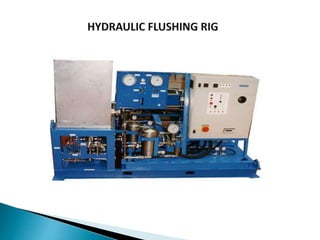
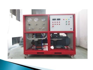
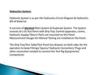
This document describes the specifications of a hydraulic flushing rig. It can be used to clean systems contaminated with large amounts of debris. The rig contains:
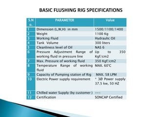
- A 300 liter stainless steel tank for hydraulic oil
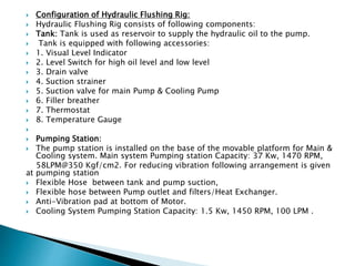
- Pumps capable of 58 LPM at 350 kg/cm2 pressure
- Filters down to 2 microns to clean the oil
- A heat exchanger to control oil temperature below 60°C
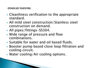
- All piping and fittings are stainless steel for use with water or oil-based fluids
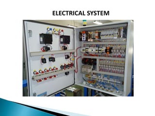
- Gauges and controls mounted on a stainless steel panel
- It can clean systems to a NAS 6 cleanliness standard and is certified.


![IRZ artificial lift solutions [version 1.2 july 2016]](https://cdn.slidesharecdn.com/ss_thumbnails/irzartificialliftsolutionsversion1-160720102154-thumbnail.jpg?width=640&height=640&fit=bounds)


