Downloaded 33 times
![IJRET: International Journal of Research in Engineering and Technology eISSN: 2319-1163 | pISSN: 2321-7308
__________________________________________________________________________________________
Volume: 03 Special Issue: 03 | May-2014 | NCRIET-2014, Available @ http://www.ijret.org 835
STATIC ANALYSIS OF HELICAL COMPRESSION SPRING
Sangmesh Pattar1
, Sanjay S.J2
, V.B.Math3
1
P.G. Student, Mechanical Engineering Department, Basaveshwar Engineering College, Karnataka, India
2
Assistant Professor, Mechanical Engineering Department, Basaveshwar Engineering College, Karnataka, India
3
Professor, Mechanical Engineering Department, Basaveshwar Engineering College, Karnataka, India
Abstract
A spring is a flexible element used to exert a force or a torque and, at the same time, to store the energy. The force can be a linear
push or pull, or it can be radial, acting similarly to a rubber band around a roll of drawings. The spring which is considered in
the paper is a part of automobile horn, where the horn is used for maintain safe distance and it is subjected to varying load. The
spring is analyzed through analytical and finite element method to check the variation in the deformation value as well as
maximum shear stress value. By the results of ANSYS it is observed that analytical results and finite element method results are
within the acceptable range.
Keywords: Spring, Automobile Horn, Finite Element Method.
-----------------------------------------------------------------------***----------------------------------------------------------------------
1. INTRODUCTION
A spring is defined as an elastic body, whose function is to
compress when loaded and to recover its original shape
when the load is removed. A spring is a flexible element used
to exert a force or a torque and, at the same time, to store
energy. The force can be a linear push or pull, or it can be
radial. The torque can be used to cause a rotation. Springs can
be classified according to the direction and the nature of the
force exerted by the spring when it is deflected. Helical
compression springs are typically made from round wire,
wrapped into a straight, cylindrical form with a constant
pitch between adjacent coils. Square or rectangular wire may
also be used. Without an applied load, the spring’s length is
called the free length. When a compression force is applied,
the coils are pressed more closely together until they all
touch, at which time the length the minimum possible is
called the solid length.
Fig –1: Model of spring
A static analysis is carried on helical compression spring
which is used in two-wheeler horn by S.S.Gaikwad et.al[1],in
his paper analytical results are compared with NASTRON
software results. Varun B. and K. K. JAIN [2], they
considered helical spring which is subjected heavy duty or
load.
Notations
D – Mean Diameter of Coil.
d – Diameter of Wire.
l – Total Length of Wire.
n – No. of active Coils.
τ – Maximum Shear Stress.
θ _ Angular deflection of the Wire.
T – Twisting Moment.
J – Polar Moment of Inertia.
W – Load.
C – Spring Index.
Δ – Deflection of the Spring.
G – Modulus of Rigidity for the spring material.
2. ANALYTICAL METHOD
In design of helical spring, initially spring considered as per
some dimensions like free length of spring, wire diameter,
mean diameter of spring, pitch of spring this dimensions either
as per calculation or as per application. But when it is
subjected to load then spring will act according to load and get
deformed or stressed so, it is important to know when spring is
subjected to load what is the maximum deflection and
maximum shear stress. Some other values are also considered
but in this paper only deflection and maximum shear stress are
considered because of application of spring needs these](https://image.slidesharecdn.com/staticanalysisofhelicalcompressionspring-140824225542-phpapp02/85/Static-analysis-of-helical-compression-spring-1-320.jpg)
![IJRET: International Journal of Research in Engineering and Technology eISSN: 2319-1163 | pISSN: 2321-7308
__________________________________________________________________________________________
Volume: 03 Special Issue: 03 | May-2014 | NCRIET-2014, Available @ http://www.ijret.org 836
values. To calculate deflection and maximum shear stress
formulas are below.
Deflection of Helical Spring of circular wire can be calculated
by [3],
2
Dx
Eq. (1)
2
T G
dJ l
Eq. (2)
Therefore
Tl
JG
or 2
l
DG
considering
Tl
JG
and substituting value of θ in Eq.1
We get
3 3
4
8 8WD n WC n
Gd Gd
C = D/d Eq. (3)
Stress in Helical Spring of circular wire can be calculated by,
3
12 16
DT Wx d
Eq. (4)
1 3
8WD
d
and
2 2
4W
d
Eq. (5)
The Resultant Shear Stress is given by
1 2 3 2
8 4WD W
d d
Eq. (6)
3. FINETE ELEMENT METHOD
The finite element method is a numerical method for solving
problems of engineering and mathematical physics. Typical
problem areas of interest in engineering and mathematical
physics that are solvable by use of the finite element method
include structural analysis, heat transfer, fluid flow, mass
transport and electromagnetic potential. For problems
involving complicated geometries, loading and material
properties, it is generally not possible to obtain analytical
mathematical solutions. Analytical solutions are those given
by a mathematical expression that yields the values of the
values of the desired unknown quantities at any location in a
body and are thus valid for a finite number of locations in the
body. These analytical solutions generally require the solution
of ordinary or partial differential equations, which because of
the complicated geometries, loading and material properties
are not usually obtainable[4].
4. LOADING AND BOUNDARY CONDITION
Component is modeled in CAD software [ ]. Spring consists of
following dimensions, wire diameter = 0.45mm, Pitch =
1.75mm, mean diameter of spring = 4.35mm, free length of
spring = 10.2mm, no. of active coil = 6. For analysis ANSYS
14.5 (workbench) is used. Since spring used in horn so, load
applied is small and in this case it is considered as 1N. Load is
varied as 1N, 2N, 3N, 4N, 5N. The spring material properties
are as mention in below table.
Table –1: Material Properties of spring
Material Stainless Steel
Modulus of elasticity 193000 N/mm2
Poisson’s ration 0.3
Density 8 E-09 tones/mm3
Shear modulus 588.99 N/mm2
Fig -2: Fixed support and load distribution.
In ANSYS software first the material properties are added,
and then CAD model is imported. In analysis part model is
meshed with required size, element (Tetra or Quadra) then
with boundary conditions. The component is loaded, in this
case spring fixed (all degrees of freedom are constrained) at
one end and other end is loaded. At last checking the required
results in this case deformation and maximum shear stress.](https://image.slidesharecdn.com/staticanalysisofhelicalcompressionspring-140824225542-phpapp02/85/Static-analysis-of-helical-compression-spring-2-320.jpg)
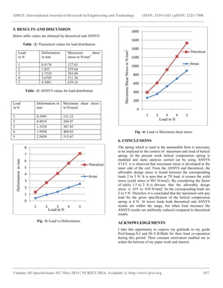
![IJRET: International Journal of Research in Engineering and Technology eISSN: 2319-1163 | pISSN: 2321-7308
__________________________________________________________________________________________
Volume: 03 Special Issue: 03 | May-2014 | NCRIET-2014, Available @ http://www.ijret.org 838
REFERENCES
[1]. S. S. Gaikwad, P. S. Kachare (2013), “Static analysis of
helical compression spring used in two-wheeler horn”. IJEAT
ISSN: 2249 – 8958, Volume-2, Issue-3.
[2]. Varun B, K. K. Jain (2013), “Analysis of closed coil
helical spring subjected to heavy duty”, IJEAT ISSN: 2320-
0804 ,Vol. 1 Issue -4.
[3]. R.S.Kurmi and J.K.Gupta (2005), Machine design, 3rd
edition, S.Chand publication, India.
[4]. D. Logan (2005), Finite element method, 5th edtion,
Celgage Learing, India.
[5]. ANSYS user manual 2014.
[6]. CATIA user manual V5R20.](https://image.slidesharecdn.com/staticanalysisofhelicalcompressionspring-140824225542-phpapp02/85/Static-analysis-of-helical-compression-spring-4-320.jpg)

The document presents a study on the static analysis of helical compression springs used in automobile horns, focusing on deformation and maximum shear stress under varying loads. It employs both analytical methods and finite element analysis (using ANSYS) to compare results, showing that the analytical and numerical outcomes fall within an acceptable range. The findings conclude that the maximum safe payload for the spring is 4N, with theoretical results remaining consistent at lower loads but diverging at higher ones.