Download to read offline

![D-NR.00 00 -06-de-09/2012 2
Ex i Power Supply
Type
Ex i
9143/10-065-200-10
9143/10-099-220-10
9143/10-104-220-10
9143/10-114-200-10
9143/10-124-150-10
9143/10-156-065-10
9143/10-156-160-10
9143/10-187-050-10
9143/10-244-06-10
9143/10-065-200-20
9143/10-104-220-20
9143/10-114-200-20
9143/10-124-150-20
9143/10-156-065-20
9143/10-156-160-20
9143/10-187-050-20
9143/10-244-060-20 Function
For the intrinsically safe operation of field devices e.g. transmitters...
x
x
x
x
x
x
x
x
x
x
x
x
x
x
x
x
x Installation
In Zone 2 & 22
x
x
x
x
x
x
x
x
x
Ex i Interfaces [Zone 1 und 21] x x x x x x x x x x x x x x x x x
Number of channels
1
1
1
1
1
1
1
1
1
1
1
1
1
1
1
1
1 Nominal voltage (UN) [V]
4,0…5,6
x
x
8,8…9,1 x
8,7…9,5
x
x
9,4…10,4 x x
9,5…11,8
x
x
12,5…14,7 x x x x
14,6…17,6
x
x
18,9…23,0 x x
Max. Nominal current IN
15 mA
35 mA
x
x
40 mA x x
45 mA
x
x
130 mA x x
140 mA
x
x
160 mA x x
180 mA
x
x
200 mA x x x
Power supply
24 V AC / DC x x x x x x x x x
85 V…230 V AC
x
x
x
x
x
x
x
x
Intrinsically safe output
[Ex ib] IIC / IIB
x
x
x
x
x
x
x
x
x
x
x
x
x
x
x
x
x Galvanic isolation
Between output and power supply
x
x
x
x
x
x
x
x
x
x
x
x
x
x
x
x
x](https://image.slidesharecdn.com/stahlisolatorsispacatexzone1zone2hazardousareaisolatorsselectionguide-140916024424-phpapp02/85/Stahl-Isolators-ISpac-ATEX-Zone-1-Zone-2-Hazardous-Area-Isolators-Selection-Guide-2-320.jpg)
![D-NR.00 00 -06-de-09/2012 3
Frequency Transmitter
Type
Ex i
Non-Ex i
9146/10-11-12
9146/20-11-11
9146/10-11-62 Function
To monitors the speed of rotating devices like fans, centrifuges, tube extruder,...
x
x
x Installation
In Zone 2 & 22
x
x
x Ex i Interfaces [Zone 0 und 20] x x
Number of Channels
1
2
1 Input signal
Gem. EN 60947-5-6 (NAMUR)
x
x
x Input frequency 0,001 Hz…20 kHz x x x
Output
0/4 mA …20 mA x x x
Limit value
2 x NO (contact per channel) x x
Pulse output
One NO selectable x x
Power supply
24 V DC x x x
Open-circuit and short-circuit
Line fault detection x x x
Potential free relay contact
x
x
x Galvanic isolating
Between input, output and power supply
x
x
x](https://image.slidesharecdn.com/stahlisolatorsispacatexzone1zone2hazardousareaisolatorsselectionguide-140916024424-phpapp02/85/Stahl-Isolators-ISpac-ATEX-Zone-1-Zone-2-Hazardous-Area-Isolators-Selection-Guide-3-320.jpg)
![D-NR.00 00 -06-de-09/2012 4
Vibration transducer
Type
Ex i
9147/10-99-10s
9147/20-99-10s Function
for intrinsically safe operation of vibration sensors, speed and acceleration sensors.
x
x Installation
in Zone 2 & 22
x
x Ex i Interfaces [Zone 0 und 20] x x
Number of channels
1
2 Ex i Input signal
Input resistance 10 kΩ
x
x
Input signal l -0,5 ... -20 V
x
x Functional range 0 ... -24 V x x
Output
-0,5 ... -20 V x x
Power supply
24 V DC x x Galvanic isolating
Between input, output and power supply
x
x](https://image.slidesharecdn.com/stahlisolatorsispacatexzone1zone2hazardousareaisolatorsselectionguide-140916024424-phpapp02/85/Stahl-Isolators-ISpac-ATEX-Zone-1-Zone-2-Hazardous-Area-Isolators-Selection-Guide-4-320.jpg)
![D-NR.00 00 -06-de-09/2012 5
Transmitter Supply Unit and Isolating Repeater (AI)
Type
Ex i
Non-Ex i 9160/13-10-11 9160/13-10-10 9160/19-10-11 9160/23-10-11 9160/23-10-10 9160/13-11-11 9160/13-11-10 9160/19-11-11 9160/19-11-10 9160/23-11-11 9160/23-11-10 9162/13-11-12
9162/13-11-14
9163/13-11-11
9163/13-10-11
9163/23-11-11
9163/23-10-11
9164/13-22-08
9164/13-22-09
9160/13-11-61
9160/19-11-61
9160/23-11-61
9162/13-11-64 Function
Transmitter supply unit with HART
x
x
x
x
x
x
x
x
x
x
x
x
x
x
x
x
x Isolating repeater for 4-ware Transmitter x x x x x x x x x x x x x x x x x
Isolating repeater for 4-ware Transmitter with HART
x
x
x
x
to integrate 4-wire transmitters with 2 wire I/O-cards x x
Installation
Zone 1 x x
Zone 2 und 22
x
x
x
x
x
x
x
x
x
x
x
x
x
x
x
x
x
x
x
x
x
x
x Ex i Interfaces [Zone 0 und 20] x x x x x x x x x x x x x x x x x x x
Number of channels
1
1
1
2
2
1
1
1
1
2
2
1
1
1
1
2
2
1
1
1
1
2
1 Duplicate signal x x x x
Input
Exi: 0/4 mA…20 mA with HART x x x x x x x x x x x x x x x x x
Non Ex i: 0/4 mA…20 mA with HART
x
x
x
x 4-wire MU (Ex i Anschluss) x
4-wire MU (Ex e Anschluss)
x
Output A
0/4 mA…20 mA with HART
x
x
x
x
x
x
x
x
x
x
x
x
x
x Passive with HART x x x x x x x
Output B
Passive without HART x
Passive with HART
x
x
0/4 mA…20 mA x x x
0/4 mA…20 mA with HART
x
x
x
Limit value contact
2 x NO
x
x
x Number of wire
2-, 3 & 4-wire transmitter and mA sources
x
x
x
x
x
x
x
x
x
x
x
x
x
x
x
x
x 4-wire HART transmitter x x x x
SIL 2 (IEC 61508)
x
x
x
x
x
x
x
x
x
x
x
x
x
x
x
x
x
x
x
x Power supply
24 V DC
x
x
x
x
x
x
x
x
x
x
x
x
x
x
x
x
x
x
x
x
x Open-circuit and short-circuit
Line fault detection
x
x
x
x
x
x
x
x
x
x
x
x
x
x
x
x
x fault message contact x x x x x x x x x x x x x x x x
fault signal contact (LED)
x
x
x
x
x
x
x
x
x
x
x
x
x
x
x
x Galvanic isolating
Between input, output
x
x
Between input, output and power supply x x x x x x x x x x x x x x x x x x x x x](https://image.slidesharecdn.com/stahlisolatorsispacatexzone1zone2hazardousareaisolatorsselectionguide-140916024424-phpapp02/85/Stahl-Isolators-ISpac-ATEX-Zone-1-Zone-2-Hazardous-Area-Isolators-Selection-Guide-5-320.jpg)
![D-NR.00 00 -06-de-09/2012 6
Isolating Repeater (AO)
Type
Ex i
Non-Ex i 9165/16-11-11 9165/16-11-10 9165/26-11-11 9165/26-11-10
9167/11-11-00
9167/21-11-00
9167/13-11-00
9167/23-11-00
9167/14-11-00
9167/24-11-00
9165/16-11-61
9165/26-11-61
9167/13-11-50
9167/23-11-50 Function
Isolating repeaters are used in the intrinsically safe operation of control valves, i/p-converters or indicators.…..
x
x
x
x
x
x
x
x
x
x
x
x
x
x Installation
In Zone 2
x
x
x
x
x
x
x
x
x
x
x
x
x
x Ex i Interfaces [Zone 0 und 20] x x x x x x x x x x
Number of channels
1
1
2
2
1
2
1
2
1
2
1
2
1
2 Input
0/4 mA…20 mA with HART
x
x
x
x
x
x
x
x
x
x
x
x
x
x Output Ex i: 0/4 mA…20 mA with HART
x
x
x
x
x
x
x
x
x
x
Non Ex i: 0/4 mA…20 mA with HART x x x x Uo / Io / Po (15,7 V / 60 mA / 233 mW)
x
x
Uo / Io / Po (18,8 V / 107 mA / 503 mW) x x
Uo / Io / Po (25 V / 99 mA / 613 mW)
x
x
Uo / Io / Po (25,6 V / 96 mA / 605 mW) x x x x
Min. load resistance RL 150 Ω
x
x
x
x
Max. load resistance RL
360 Ω
x
x
590 Ω x x
800 Ω
x
x
x
x SIL (IEC 61508)
SIL 2
x
x
x
x
x
x
SIL 3 x x x x x x x x
Power supply
24 V DC x x x x x x
Loop power
x
x
x
x
x
x
x
x Open-circuit and short-circuit
Line fault detection
x
x
x
x
x
x
fault message contact x x x x
fault signal contact (LED)
x
x
x
x
x
x
Galvanic isolating
Between input and output
x
x
x
x
x
x
x
x
x
x Between input, output and power supply x x x x](https://image.slidesharecdn.com/stahlisolatorsispacatexzone1zone2hazardousareaisolatorsselectionguide-140916024424-phpapp02/85/Stahl-Isolators-ISpac-ATEX-Zone-1-Zone-2-Hazardous-Area-Isolators-Selection-Guide-6-320.jpg)
![D-NR.00 00 -06-de-09/2012 7
Switching Repeater and Ex i Relay Module (DI)
Type
Ex i 9170/10-11-11 9170/11-11-13 9170/10-11-21 9170/20-10-11 9170/20-11-11 9170/21-11-13 9170/20-10-21 9170/20-11-21 9170/10-12-11 9170/10-12-21 9170/10-13-21 9170/20-12-11 9170/20-12-21
9170/11-14-11
9170/21-14-11
9170/11-14-12
9170/11-14-12- C1515 *)
9170/21-14-12
9170/21-14-12- C1515*)
9172/10-11-00
9172/20-11-00 Function
For intrinsically safe operation of contacts, optocoupler outputs etc. x x x x x x x x x x x x x x x x x x
x
Relay Ex i activation / Non-Ex i contact x x
Installation
In Zone 2 x x x x x x x x x x x x x x
Ex i Interfaces [Zone 0 und 20]
x
x
x
x
x
x
x
x
x
x
x
x
x
x
x
x Number of channels 1 1 1 2 2 2 2 2 1 1 1 2 2 1 2 1 1 2 2 1 2
Input intrinsically safe input
[Ex ia] IIC x x x x x x x x x x x x x x x x x x x x x
Output per channel
1 x Changeover (125 V / 1 A) x x x
1 x Changeover (250 V / 4 A)
x
x
x
x
x 2 x Changeover (125 V / 1 A) x x x
2 x Changeover (250 V / 4 A)
x
x
2 x NO (125 V / 1 A) x x x
1 x Electronic (35 V/50mA)
x
x
x
x
x
x
Transmission frequency
≤ 6 Hz
x
x
x
x
x
≤ 15 Hz x x x x x x x x x x
≤ 10 kHz
x
x
x
x
x
x
SIL 2 (IEC 61508) x x x x x x x x x x x x x x x x x x x x x
Power supply
24 V DC x x x x x x x x x x x x x
110 V … 230 V
x
x
x
x
x
x
Loop power x x
Line fault transparency (LFT)
x
x
x
x
Open-circuit and short-circuit
Line fault detection
x
x
x
x
x
x
x
x
x
x
x
x
x
x
x
x
x
x
x
fault message contact x x x x x x x x x x x x
fault signal contact (LED)
x
x
x
x
x
x
x
x
x
x
x
x
x
x
x
x
x
x
x
Galvanic isolating
Between input and output
x
x Between input, output and power supply x x x x x x x x x x x x x x x x x x x
*) only for Yokogawa ProSafe-RS I/O Modules SDV 144](https://image.slidesharecdn.com/stahlisolatorsispacatexzone1zone2hazardousareaisolatorsselectionguide-140916024424-phpapp02/85/Stahl-Isolators-ISpac-ATEX-Zone-1-Zone-2-Hazardous-Area-Isolators-Selection-Guide-7-320.jpg)
![D-NR.00 00 -06-de-09/2012 8
Binary Output and Ex i Relay Module (DO)
Type
With power supply(9175)
Loop power (9176 & 9172)
9175/10-12-11
9175/20-12-11
9175/10-12-12
9175/10-14-11
9175/20-14-11
9175/10-14-12
9175/10-16-11
9175/10-16-11- C1329
9175/20-16-11
9175/20-16-11- C1329
9175/10-16-12
9176/10-12-00
9176/20-12-00
9176/10-14-00
9176/20-14-00
9176/10-15-00
9176/20-15-00
9176/10-16-00
9176/20-16-00
9176/10-17-00
9176/20-17-00
9172/11-11-00
9172/21-11-00 Function
Binary output for the intrinsically safe operation of Ex i solenoid valves or indicators.
x
x
x
x
x
x
x
x
x
x
x
x
x
x
x
x
x
x
x
x
x
Relay for Non-Ex i Activation / Ex i Contact x x
Installation
in Zone 2 x x x x x x x x x x x x x x x x x x x x x x x
Ex i Interface [Zone 0 und 20]
x
x
x
x
x
x
x
x
x
x
x
x
x
x
x
x
x
x
x
x
x
x
x Number of channels 1 2 1 1 2 1 1 1 2 2 1 1 2 1 2 1 2 1 2 1 2 1 2
Intrinsically safe output
[Ex ia] IIC x x x x x x x x x x x x x x x x x x x x x x x
[Ex ib] IIC
x
x
x
x
x
x
x
x
x
x
x
x
x
x
x
x
Ex i , 1 changeover (125 V / 4 A; 30 V / 4 A) x x
Max. Output current (IA max)
29 mA x x 35 mA x x x x x x x 40 mA x x
45 mA
x
x
x
x
x
60 mA x x x x x Parallel interconnection 58 mA x Parallel interconnection 70 mA x x x Parallel interconnection 80 mA x Parallel interconnection 90 mA x x
Parallel interconnection 120 mA
x
x
Internal resistance Ri
130 Ω
x
x
x
x
x
150 Ω x x x x x
460 Ω
x
x
250 Ω x x x x x x x
320 Ω
x
x
Parallel interconnection 65 Ω x x
Parallel interconnection 75 Ω
x
x
Parallel interconnection 125 Ω x x x
Parallel interconnection 160 Ω
x
Parallel interconnection 230 Ω x
NO-load voltage (UA)
10 V x x x x x
17,5 V
x
x
x
x
x
25 V x x x x x x x x x x x SIL 2 (IEC 61508) x x x
x x SIL 3 (IEC 61508) x x x x x x x x x x x x x x x x x x
Power supply
24 V DC x x x x x x x x x x x
Loop power
x
x
x
x
x
x
x
x
x
x
x
x Line fault transparent (LFT) x x x
Open-circuit and short-circuit
Line fault detection x x x x x x x x x x x
fault message contact
x
x
x
x
x
x
x
x
x
x
x
fault signal contact (LED) x x x x x x x x x x x
Galvanic isolating
Between input and output x X**) x x X**) x x x X**) X**) x x x x x x x x x x x x x
Between input, output and power supply
x
x
X***)
x
X***)
x
x
x
x
x***)
*) only for Yokogawa ProSafe-RS I/O Modules SDV 541 **) No galvanic isolating between outputs
***) No galvanic isolating between output and power supply](https://image.slidesharecdn.com/stahlisolatorsispacatexzone1zone2hazardousareaisolatorsselectionguide-140916024424-phpapp02/85/Stahl-Isolators-ISpac-ATEX-Zone-1-Zone-2-Hazardous-Area-Isolators-Selection-Guide-8-320.jpg)
![D-NR.00 00 -06-de-09/2012 9
Resistance Isolator and Temperature Transmitter (TI)
Type
Ex i
Non-Ex i
9180/10-77-11
9180/20-77-11
9180/11-77-11
9180/21-77-11
9182/10-51-11
9182/20-51-11
9182/10-59-11
9182/10-59-13
9182/10-51-13
9182/10-50-12
9182/20-50-12
9182/10-51-12
9182/10-51-14
9182/10-51-61
9182/20-51-61
9182/10-51-63
9182/10-59-63
9182/10-51-64 Function
Resistance Isolator for intrinsically safe operation of Pt 100 resistance thermometer or other resistance sensors
x
x
x
x
Temperature Transmitter for intrinsically safe operation of temperature sensors x x x x x x x x x x x x x x
Installation
In Zone 2 x x x x x x x x x x x x x x x x x x
Ex i interfaces [Zone 0 und 20]
x
x
x
x
x
x
x
x
x
x
x
x
x
Number of channels 1 2 1 2 1 2 1 1 1 1 2 1 1 1 2 1 1 1
Sensor
Ex i: Pt 100 Resistance Isolator x x
Ex i: Pt 1000 Resistance Isolator
x
x
Ex i: Most currently available sensors can be connected, thermocouples and resistance transmitters x x x x x x x x x
Non Ex i: Most currently available sensors can be
connected, thermocouples and resistance transmitters
x
x
x
x
x Output
0/4 mA…20 mA active
x
x
x
x
x
x
x
x
x 0/4 mA…20 mA passive x x x
Resistance value
x
x
x
x
Measurement range
18 Ω … 391 Ω
x
x
180 Ω … 3910 Ω x x
Limit value contact (per channel)
2 x NO x x x x x
Configuration
PC x x x x x x x x x x x x x x
DIP-switches
x
x
x
x
x
Power supply
24 V
x
x
x
x
x
x
x
x
x
x
x
x
x
x
x
x
x
x SIL 2 (IEC 61508) x x x x x x
Open-circuit and short-circuit
Line fault detection x x x x x x x x x x x x x x x x x x
fault message contact
x
x
x
x
x
x
x
x
x
x
x
x
x
x
x
x
x
x fault signal contact (LED) x x x x x x x x x x x x x x x x x x
Galvanic isolating
Between input, output and power supply x x x x x x x x x x x x x x x x x x](https://image.slidesharecdn.com/stahlisolatorsispacatexzone1zone2hazardousareaisolatorsselectionguide-140916024424-phpapp02/85/Stahl-Isolators-ISpac-ATEX-Zone-1-Zone-2-Hazardous-Area-Isolators-Selection-Guide-9-320.jpg)
![D-NR.00 00 -06-de-09/2012 10
Fieldbus Isolating Repeater
Type
Ex i
Non- Ex i
9185/11-35-10
9185/11-45-10
9185/11-46-10
9186/12-11-11
9186/15-12-11
9186/25-12-11
9185/12-45-10
9185/12-46-10 Function
Fieldbus Isolating Repeater
x
x
x
Fieldbus (Bridge) x x
Fibre Optic Isolating Repeater
x
x
x
Number of channels 1 1 1 2 2 1 1 1
Interface
Profibus DP / Modbus RTU x x x x
Ex i Profibus DP / Modbus RTU
x
Installation in
Zone 1
x
Zone 2, 22 x x x x x x x x
Ex i interface [Zone 1 und 21]
x
x
x
LWL interface [Zone 0 und 20] x x x
RS 485 interface [Zone 1 und 21]
x
Transmission speed
1,2 kbit/s...1,5 Mbit/s
x
x
x
x
9,6 kbit…1,5 Mbit/s x x x x
Interface field area
RS 485 IS x x x
Ex op is
x
x
RS 485 x
RS 422
x
x RS 422 Ex i x x
Interface safe area
RS 485 (X2) x x x x x
RS 422 (X2)
x
x
x
RS 232 (X1) x x x x x
Ex op is
x
Profibus-DP (X2) x x
Network structure
Line structure x x x
Point-to-Point Structure
x
x
Ring structure x x x
Hilfsenergie 24 V UC
x
x
x
x
x
x
x
x Line fault detection x x x x x x
Galvanic isolating
Between input, output and power supply x x x x x x x x](https://image.slidesharecdn.com/stahlisolatorsispacatexzone1zone2hazardousareaisolatorsselectionguide-140916024424-phpapp02/85/Stahl-Isolators-ISpac-ATEX-Zone-1-Zone-2-Hazardous-Area-Isolators-Selection-Guide-10-320.jpg)

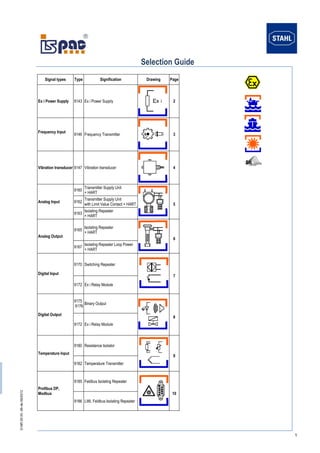
The document is a selection guide for various types of signal modules used in hazardous areas including: - Ex i power supplies for field devices - Frequency transmitters to monitor rotating equipment speeds - Vibration transducers for vibration sensors - Transmitter supply units and isolating repeaters for analog inputs and outputs - Switching repeaters and relay modules for digital inputs and outputs For each type, the guide lists relevant product types, functions, installation areas, specifications, approvals and certifications. It provides an overview of a product portfolio for intrinsically safe signal transmission in industrial process automation applications.


