Download to read offline
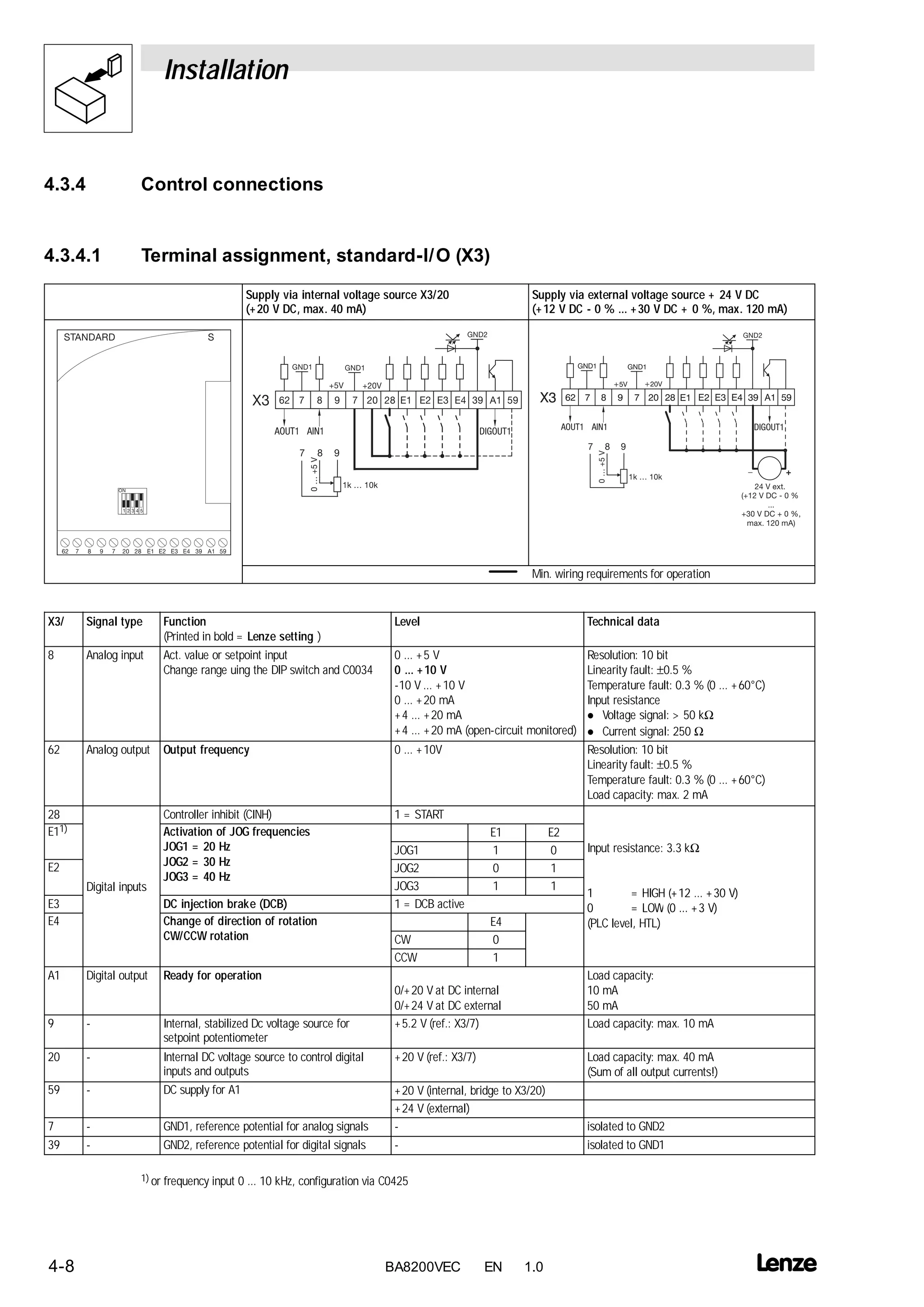

This document provides instructions for connecting control signals to the standard I/O terminal X3 of a Lenze BA8200VEC frequency inverter. It lists the terminal assignments and technical specifications for the analog input, analog output, digital inputs, and digital output connections. The analog input can be configured for various voltage and current signals. The analog output provides speed feedback between 0-10V. The digital inputs allow for functions like start, jog speeds, and direction control. The digital output indicates the inverter is ready. Internal voltage sources of +5V and +20V are provided for analog signals, while +20V or +24V external sources can be used for digital signals.


