Downloaded 103 times


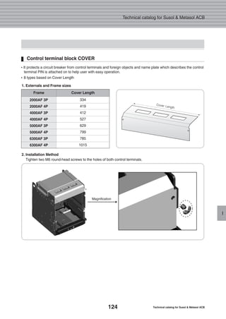
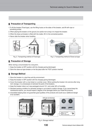
![23
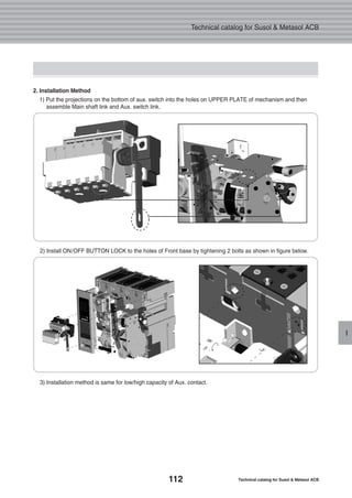
Internal Electrical Accessories
C
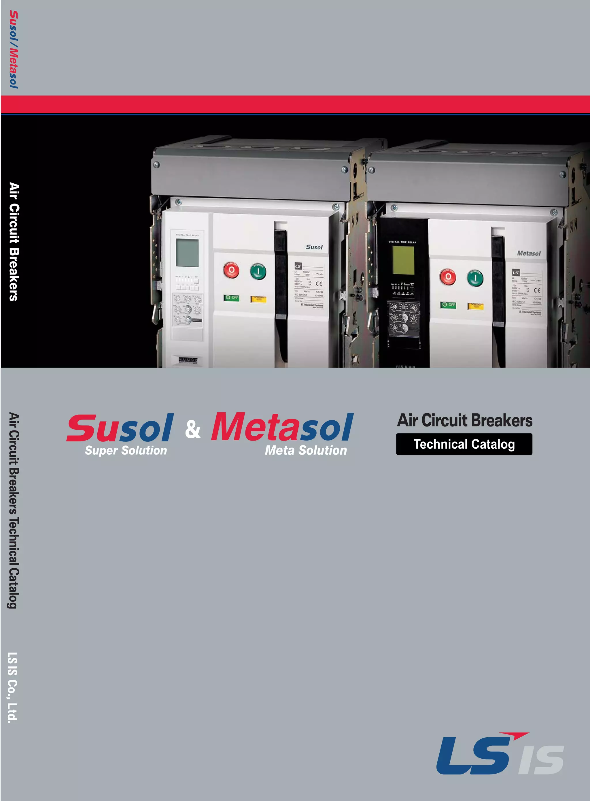
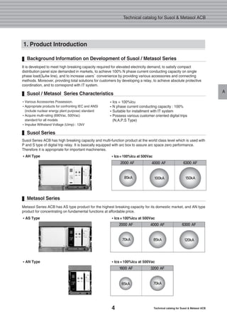
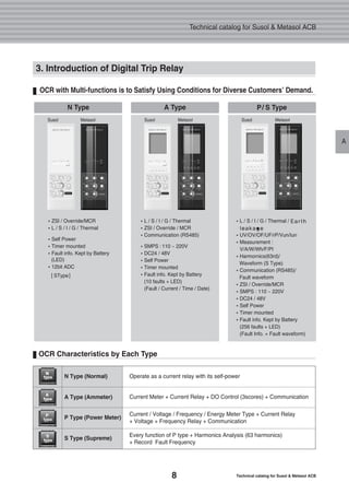
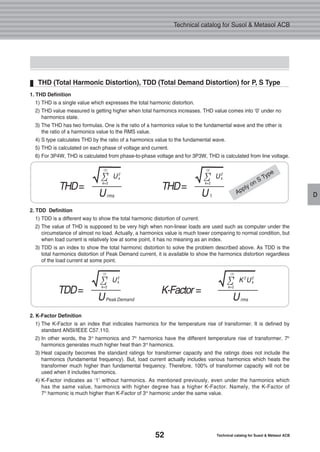
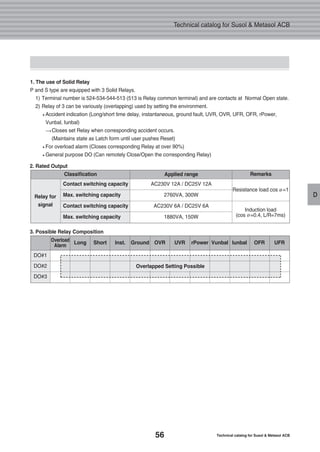
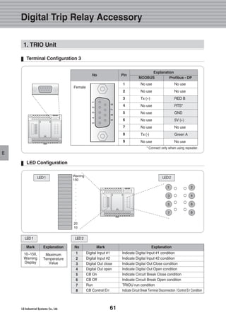
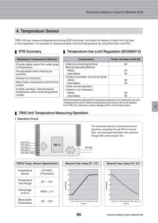
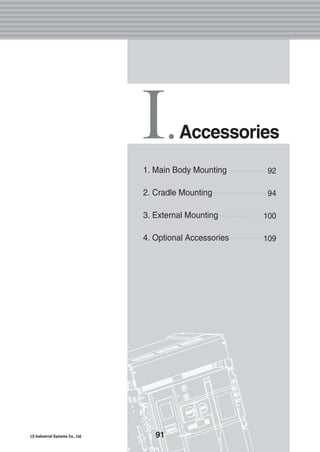
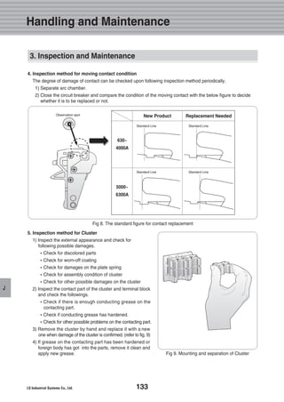
�It is a control device which closes or trips a circuit breaker from remote place when applying voltage
continuously or instantaneously to coil terminals (C1, C2).
Refer to the below table regarding the
length of wire when using trip coil with
24~30[V] or 48~60[V] of rated voltage
as power consumption due to inrush
current is about 200VA for coil operation.
Coil can be non-operating in case of not
corresponding with the wire specification
listed below.
The Specification of Using Wire
Rated Voltage[Vn] Power Consumption(VA or W)Operating Voltage Range[V] Trip Time [ms]
Shunt
Coil
Closing
Coil
Shunt
Coil
Closing
Coil
24 ~ 30
48 ~ 60
100 ~ 130
200 ~ 250
-
-
48
100 ~ 130
200 ~ 250
380 ~ 480
0.75 ~ 1.1 Vn
0.75 ~ 1.1 Vn
0.75 ~ 1.1 Vn
0.75 ~ 1.1 Vn
0.75 ~ 1.1 Vn
0.6 ~ 1.1 Vn
0.6 ~ 1.1 Vn
0.56 ~ 1.1 Vn
0.56 ~ 1.1 Vn
0.56 ~ 1.1 Vn
200
�Note) Operating voltage range is the min. rated standard for each rated voltage (Vh).
The Recommended Max. Wire Length
Closing Coil Shunt Coil
5
Less
than
40ms
Less
than
65ms
DC [V] AC [V]
Wire type
100%
85%
#14 AWG
(2.08mm2)
Operating
voltage
95.7 m
314 ft
62.5 m
205 ft
Rated Voltage [Vn]
DC 24~30 [V] DC/AC 48 [V]
#16 AWG
(1.31mm2)
61 m
200 ft
38.4 m
126 ft
#14 AWG
(2.08mm2)
457.8 m
1,503 ft
291.7 m
957 ft
#16 AWG
(1.31mm2)
287.7 m
944 ft
183.2 m
601 ft
Rated Voltage and Characteristics of Closing / Shunt coil
External Configuration and Wiring Diagram
Inrush Steady-State
External Configuration External ConfigurationWiring Diagram Wiring Diagram
1. Closing and Shunt Coil](https://image.slidesharecdn.com/metasolsusolacbtechnical201210-161116085854/85/Catalog-Metasol-Susol-ACB-LS-technical-25-320.jpg)
![24 Technical catalog for Susol & Metasol ACB
Technical catalog for Susol & Metasol ACB
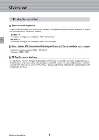
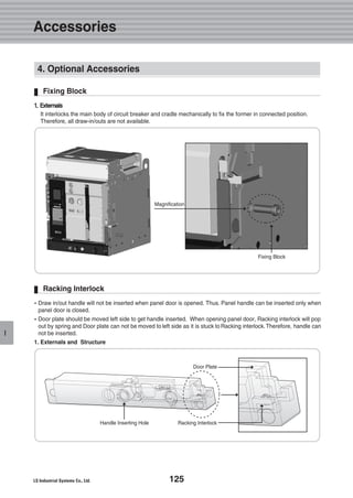
C
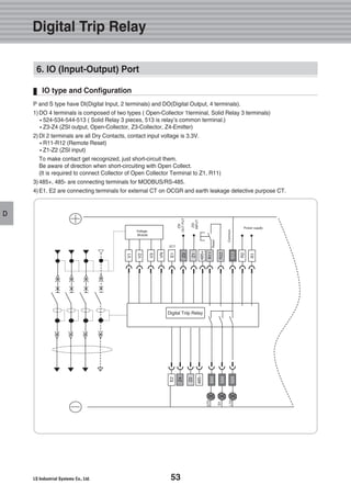
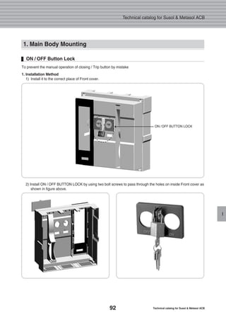
External Configuration
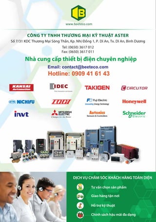
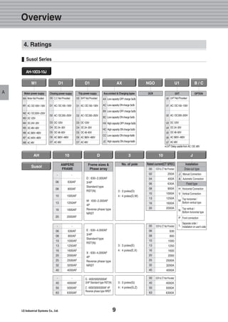
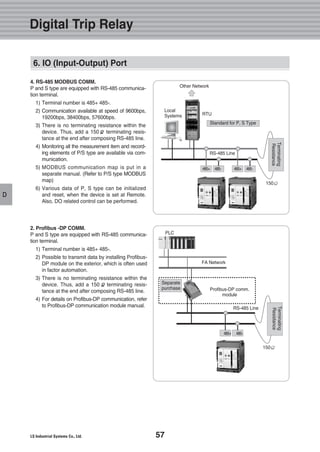
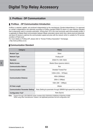
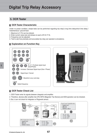
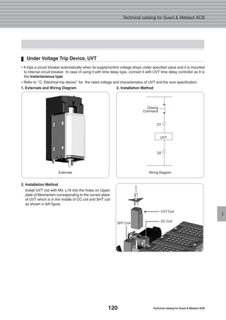
�UVT installed inside of the circuit breaker opens the circuit breaker when its supply or control voltage drops below
the specified voltage.Please connect with UVT time-delay device in order to present the time-delay function
because UVT is technically instantaneous type.
�The closing of a circuit breaker is impossible mechanically or electrically if control power not supplied to UVT.
To close the circuit breaker, 65~85% of rated voltage should be applied to both terminals of UVT coil (D1, D2).
Rated Voltage[Vn] Power Consumption(VA or W)Operating Voltage Range [V] Trip Time
[ms]
24 ~ 30
48 ~ 60
100 ~ 130
200 ~ 250
-
0.65 ~ 0.85 Vn 0.4 ~ 0.6 Vn 200 5
�Note) Operating voltage range is the min. rated standard for each rated voltage (Vh).
Less than
50ms
DC [V]
-
48
100 ~ 130
200 ~ 250
380 ~ 480
AC [V] InrushDrop-OutPick-Up Steady-State
Refer to the below table regarding the
length of wire when using trip coil with
24~30[V] or 48~60[V] of rated voltage
as power consumption due to inrush
current is about 200VA for coil operation.
Coil can be non-operating in case of not
corresponding with the wire specification
listed below.
The Specification of Using Wire
The Recommended Max. Wire Length
Wire Type
100%
85%
#14 AWG
(2.08mm2)
Operating
Voltage
48.5 m
159 ft
13.4 m
44 ft
Rated Voltage [Vn]
DC 24~30 [V] DC/AC 48 [V]
#16 AWG
(1.31mm2)
30.5 m
100 ft
8.8 m
29 ft
#14 AWG
(2.08mm2)
233.2 m
765 ft
62.5 m
205 ft
#16 AWG
(1.31mm2)
143.9 m
472 ft
39.3 m
129 ft
Rated Voltage and Characteristics of UVT
External Configuration and Wiring Diagram
2. Under Voltage Trip device, UVT
Wiring Diagram](https://image.slidesharecdn.com/metasolsusolacbtechnical201210-161116085854/85/Catalog-Metasol-Susol-ACB-LS-technical-26-320.jpg)
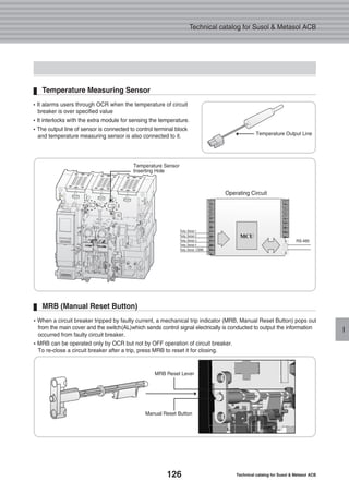
![25
Internal Electrical Accessories
C
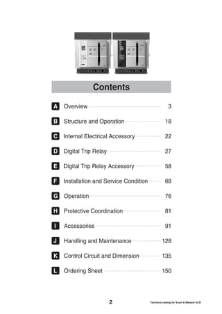
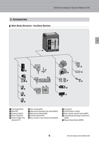
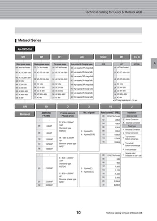
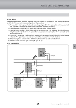
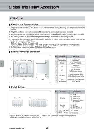
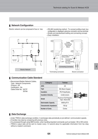
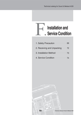
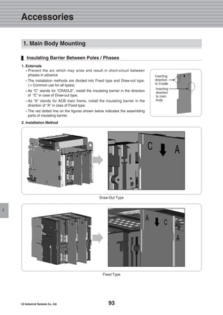
�Use UVT time delay controller to prevent the trip of a circuit breaker due to the operation of instantaneous type
UVT when voltage dips occurred instantly on main or control power supply.
�If combining UVT time delay controller and instantaneous type UVT mounted in circuit breaker, it makes a trip
operation after a certain time when its main or control voltage drop below specified value to prevent the
unexpected trip operation caused from instant blackout.
�It is the outdoor type and can be used by mounting to inside distribution panel or the cradle of circuit breaker.
�It provides control signal (output contact) to indicate the trip status of circuit breaker caused from UVToperation
for indoor type. If control voltage supplied to UVT under normal operation, b contact is conducted and if circuit
breaker is tripped due to UVT operation, a contact is conducted.
Rated Voltage[Vn] Power Consumption(VA or W)Operating Voltage Range [V] Trip Time
[s]
24 ~ 30
100 ~ 130
200 ~ 250
-
0.65 ~ 0.85 Vn 0.4 ~ 0.65 Vn 200 5
�Note) Operating Voltage Range is the min. rated standard for each rated voltage (Vh).
0.5, 1,
1.5, 3
DC [V]
48
100 ~ 130
200 ~ 250
380 ~ 480
AC [V] InrushPick-Up Drop-Out Steady-State
Rated Voltage and Characteristics of UVT Time Delay Controller
Rated Voltage[V] Rated Current(A), Resistive Load Max. Switching Voltage(V) Max. Switching Current(V)
24V DC
120V AC
250V AC
12
12
10
110V DC
250V A C
15
Rated Output Contact
External Configuration and Wiring Diagram
3. UVT Time Delay Controller
External Configuration Wiring Diagram](https://image.slidesharecdn.com/metasolsusolacbtechnical201210-161116085854/85/Catalog-Metasol-Susol-ACB-LS-technical-27-320.jpg)
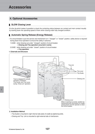
![26 Technical catalog for Susol & Metasol ACB
Technical catalog for Susol & Metasol ACB
C
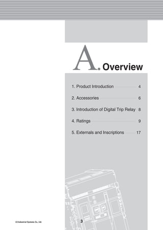
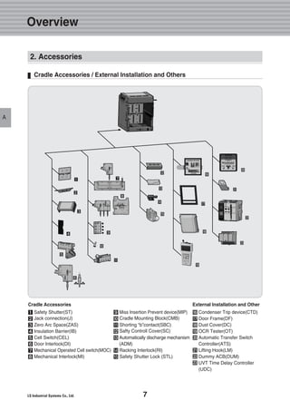
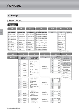
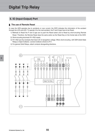
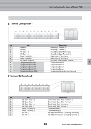
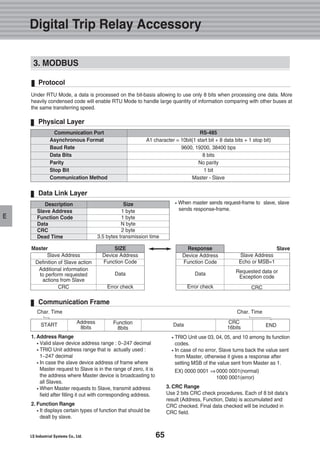
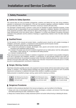
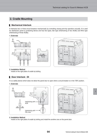
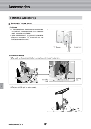
�In case a circuit breaker is tripped by OCR which operates against the faulty current (Over Current Relay),
Trip Alarm switch provides the information regarding the trip of circuit breaker by sending the electrical signal from
the mechanical indicator on main cover of main circuit breaker or internal auxiliary switch.
�When a circuit breaker tripped by faulty current, a mechanical trip indicator (MRB, Manual Reset Button) pops out
from the main cover and the switch (AL) which sends control signal electrically is conducted to output the
information occurred from faulty circuit breaker.
�MRB can be operated only by OCR but not by OFF operation of circuit breaker.
�To re-close a circuit breaker after a trip, press MRB to reset it for closing.
�2pcs of Electrical trip switch (AL1, AL2, 1a) are provided (OPTION)
4. Trip Alarm Switch, AL
Rated Voltage
[Vn]
Non-Inductive Load (A) Rated Voltage Inrush
Current
8V DC
30V DC
125V DC
250V DC
250V AC
11
10
0.6
0.3
11
3
3
0.1
0.05
1.5
6
6
0.6
0.3
6
3
3
0.1
0.05
2
MAX. 24A
Resistive Load Lamp Load Motor LoadInductive Load (A)
Electrical Characteristics of AL Switch
Externals
AL2, 1a
AL1, 1a](https://image.slidesharecdn.com/metasolsusolacbtechnical201210-161116085854/85/Catalog-Metasol-Susol-ACB-LS-technical-28-320.jpg)
![32 Technical catalog for Susol & Metasol ACB
Technical catalog for Susol & Metasol ACB
DD
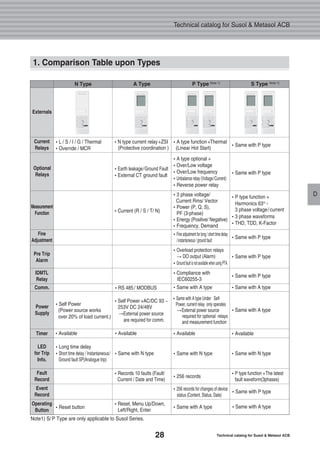
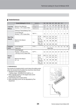
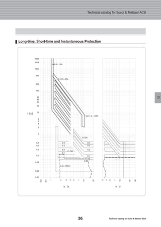
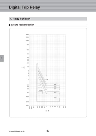
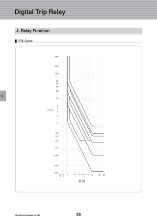
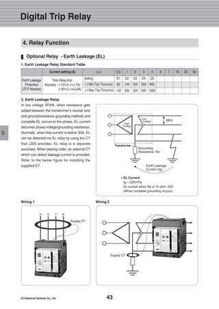
4. Relay Function
Long- Time Delay Relays
Long-Time
Delay(L)
Short-Time
Delay(S)
Instantane
ous(I)
Ground
Fault
Maximum time delay(sec)
Accuracy:±15% or below 100ms
Continuous Thermal Memory Time
Current Setting(A)
Accuracy:±10% or below 50ms
Maximum time delay(s)
@ 10×Ir
Current Setting(A)
Tripping time
Current Setting(A)
Accuracy:±10%(Ig≥0.4In)
±20%(Ig≥0.4In) or below 50ms
Maximum time delay(s)
@ 1×In
tr@(1.5×Ir)
tr@(6.0×Ir)
tr@(7.2×Ir)
Isd=Ir× ...
Tsd
Ii=In× ...
Ig=In× ...
tg
12.5
0.5
0.34
1.5
0.05
20
80
2
0.2
0.05
20
80
25
1
0.69
2
0.1
0.1
80
140
3
0.3
0.1
0.1
80
140
50
2
1.38
3
0.2
0.2
160
240
4
0.4
0.2
0.2
160
240
100
4
2.7
4
0.3
0.3
260
340
6
0.5
0.3
0.3
260
340
200
8
5.5
5
0.4
0.4
360
440
8
0.6
0.4
0.4
360
440
300
12
8.3
6
10
0.7
400
16
11
8
12
0.8
500
20
13.8
10
15
1.0
off
off
off
off
off
off
I2T off
I2T on
Min. Trip
Time(ms)
Max. Trip
Time(ms)
I2t off
I2t on
Min. Trip
Time(ms)
Max. Trip
Time(ms)
Current Setting(A) (1.15××Ir) Ir = In ×× ... 0.4 0.5 0.6 0.7 0.8 0.9 1.0
below 50ms
1. Long- Time Delay
The function for overload protection which has time delayed
characteristic in inverse ratio to fault current. (T = I^2 / K).
1) Standard current setting Knob-Ir
�Setting range : (0.4, 0.5, 0.6, 0.7, 0.8, 0.9, 1.0) In
2) Time delay setting Knob-Tr
�Standard operating time is based on the time of 6lr.
�Setting range : 0.5/ 1/ 2/ 4/ 8/ 12/ 16/ 20/ Off sec (9 modes)
3) Relay starting current
�When current over (1.15) Ir flows in, relay is picked up.
4) Long-Time Delay Operating Characteristic Formula
�T = τXln(I X Ip )/(I X K )
T = Operating time [ ms ] τ= 29250*Tr
I = Overload rate Ip = Load rate before Overload
K = 1.10(Service Factor)
5) Relay operates basing on the largest load current
among R/S/T/N Phase.
6) Rated current can be adjustable by Fine Adjustment Note1)
Note1) Fine Adjustment
The function for adjusting relay operating current much more
detailed than the value of knob
2 2 2 2](https://image.slidesharecdn.com/metasolsusolacbtechnical201210-161116085854/85/Catalog-Metasol-Susol-ACB-LS-technical-34-320.jpg)
![33
D
Digital Trip Relay
D
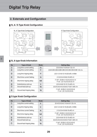
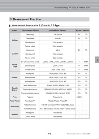
4. Relay Function
Short-Time Delay Relays
Long-Time
Delay(L)
Short-Time
Delay(S)
Instantane
ous(I)
Ground
Fault
Maximum time delay(sec)
Accuracy:±15% or below 100ms
Continuous Thermal Memory Time
Current Setting(A)
Accuracy:±10% or below 50ms
Maximum time delay(s)
@ 10×Ir
Current Setting(A)
Tripping time
Current Setting(A)
Accuracy:±10%(Ig≥0.4In)
±20%(Ig≥0.4In) or below 50ms
Maximum time delay(s)
@ 1×In
tr@(1.5×Ir)
tr@(6.0×Ir)
tr@(7.2×Ir)
Isd=Ir× ...
Tsd
Ii=In× ...
Ig=In× ...
tg
12.5
0.5
0.34
1.5
0.05
20
80
2
0.2
0.05
20
80
25
1
0.69
2
0.1
0.1
80
140
3
0.3
0.1
0.1
80
140
50
2
1.38
3
0.2
0.2
160
240
4
0.4
0.2
0.2
160
240
100
4
2.7
4
0.3
0.3
260
340
6
0.5
0.3
0.3
260
340
200
8
5.5
5
0.4
0.4
360
440
8
0.6
0.4
0.4
360
440
300
12
8.3
6
10
0.7
400
16
11
8
12
0.8
500
20
13.8
10
15
1.0
off
off
off
off
off
off
I2T off
I2T on
Min. Trip
Time(ms)
Max. Trip
Time(ms)
I2t off
I2t on
Min. Trip
Time(ms)
Max. Trip
Time(ms)
Current Setting(A) (1.15××Ir) Ir = In ×× ... 0.4 0.5 0.6 0.7 0.8 0.9 1.0
below 50ms
The function for fault current (over current) protection which
has time delayed and definite time characteristic in inverse
ratio to fault current.
1) Standard current setting Knob-Isd
�Setting range : 1.5/ 2/ 3/ 4/ 5/ 6/ 8/ 10/ OFF Ir
2) Time delay setting Knob-Tsd
�Standard operating time is based on the time of 10lr.
�Inverse time (I2T On ) : 0.1/0.2/0.3/0.4 Sec
�Definite time (I2T Off) : 0.05/0.1/0.2/0.3/0.4 Sec
3) Short-Time Delay Operating Characteristic Formula
�T = td / I
T= Operating time [ms] Td = 1000*Tsd
I = Overload rate (Over current/Ir)
4) Relay operates basing on the largest load current among
R/S/T/N Phase.
5) Relay operating current can be adjustable by Fine Adjustment
6) Relay can operate at instantaneous current through ZSInote1)
Note1) ZSI : Zone Selective Interlocking
The Lowest equipment pre-arranged with ZSI will operate
instantaneously regardless of time delay setting.
1. Short-Time Delay
2](https://image.slidesharecdn.com/metasolsusolacbtechnical201210-161116085854/85/Catalog-Metasol-Susol-ACB-LS-technical-35-320.jpg)
![35
D
Digital Trip Relay
D
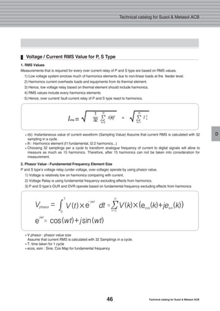
4. Relay Function
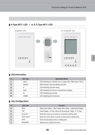
Ground Fault
Long-Time
Delay(L)
Short-Time
Delay(S)
Instantane
ous(I)
Ground
Fault
Maximum time delay(sec)
Accuracy:±15% or below 100ms
Continuous Thermal Memory Time
Current Setting(A)
Accuracy:±10% or below 50ms
Maximum time delay(s)
@ 10×Ir
Current Setting(A)
Tripping time
Current Setting(A)
Accuracy:±10%(Ig≥0.4In)
±20%(Ig≥0.4In) or below 50ms
Maximum time delay(s)
@ 1×In
tr@(1.5×Ir)
tr@(6.0×Ir)
tr@(7.2×Ir)
Isd=Ir× ...
Tsd
Ii=In× ...
Ig=In× ...
tg
12.5
0.5
0.34
1.5
0.05
20
80
2
0.2
0.05
20
80
25
1
0.69
2
0.1
0.1
80
140
3
0.3
0.1
0.1
80
140
50
2
1.38
3
0.2
0.2
160
240
4
0.4
0.2
0.2
160
240
100
4
2.7
4
0.3
0.3
260
340
6
0.5
0.3
0.3
260
340
200
8
5.5
5
0.4
0.4
360
440
8
0.6
0.4
0.4
360
440
300
12
8.3
6
10
0.7
400
16
11
8
12
0.8
500
20
13.8
10
15
1.0
off
off
off
off
off
off
I2T off
I2T on
Min. Trip
Time(ms)
Max. Trip
Time(ms)
I2t off
I2t on
Min. Trip
Time(ms)
Max. Trip
Time(ms)
Current Setting(A) (1.15××Ir) Ir = In ×× ... 0.4 0.5 0.6 0.7 0.8 0.9 1.0
below 50ms
The function for breaking ground fault current above setting
value after time-delay to protect the circuit from ground fault.
1. Standard current setting Knob-Ig
�Setting range: 0.2/0.3/0.4/0.5/0.6/0.7/0.8//1.0/OFF In
2. Time delay setting Knob-Tg
�Inverse time (I2T On ) : 0.1/0.2/0.3/0.4 Sec
�Definite time (I2T Off) : 0.05/0.1/0.2/0.3/0.4 Sec
3. Ground Fault Operating Characteristic Formula �T = td / I2
T= Operating time [ms] Td = 1000*Tsd
I = Overload rate (Ground fault current/Standard current)
4. Ground Fault Current = R + S + T + N (Vector Sum)
5. Relay operating current can be adjustable with detailed setting.
6. Relay can operate at instantaneous current through ZSI.
7. Categorize Internal CT Type (Standard Type)note1) and
External CT Type (Separate Order)note2)
Note1) Internal CT Type : Correct relay as the vector sum of
CT on internal R/S/T/N phase
Note2) External CT Type : Install an external CT to be suitable for the
value of ground fault current and then connect to inside of ACB.
In this case, arrange 5A for secondary rating output of CT and set 5A
for standard rating of relays.
1. Ground Fault](https://image.slidesharecdn.com/metasolsusolacbtechnical201210-161116085854/85/Catalog-Metasol-Susol-ACB-LS-technical-37-320.jpg)
![45
D
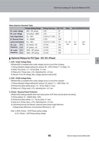
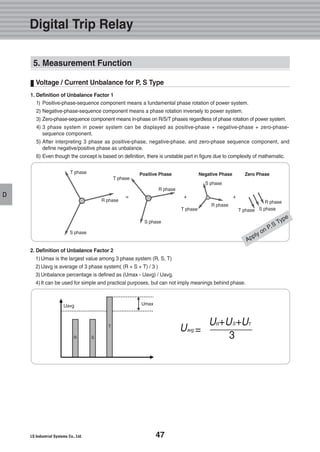
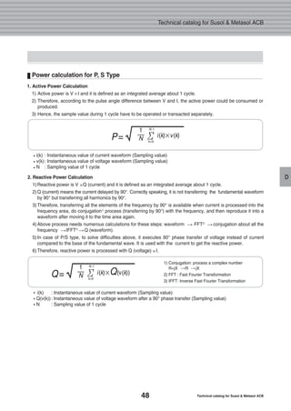
Voltage Input / Specification for P, S Type
1. Voltage Input
1) Rated voltage input
Measurement range 60V ~ 690V
Relay range 80V ~ 900V
2) Voltage input method
3P4W : Connect R/S/T/N phase to the corresponding terminal of voltage dividing module
3P3W : Attach voltage of S phase to the terminal of N phase after connecting R/S/T phase to the corresponding
terminal of voltage dividing module
3) Voltage accuracy : 1.0% (F/S) (min. indication unit: 1V)
3P 4W Voltage Wiring 3P 3W Voltage Wiring
[Voltage Dividing Module]
V0
V3
V2
V1
V0
V3
V2
V1
Vr Vs Vt Vn Vr Vs Vt
3P voltage
[Voltage Dividing Module] [Voltage Dividing Module]
Digital Trip Relay
5. Measurement Function](https://image.slidesharecdn.com/metasolsusolacbtechnical201210-161116085854/85/Catalog-Metasol-Susol-ACB-LS-technical-47-320.jpg)

![62 Technical catalog for Susol & Metasol ACB
Technical catalog for Susol & Metasol ACB
E
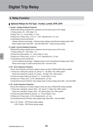
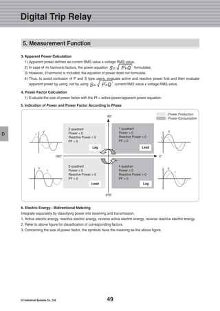
Product Input Rating
Apply Voltage
Rated Frequency
Rated Control Power
CB Condition General Type DI
Power Consumption
Category Scope Note
220V
60Hz
AC 92 ~ 253V ( Free Voltage )
TTL, Dry Type [Voltage 3.3V~5V]
Normal : Below 5W Operation : Below 10W In Operation - Relay Output
Product Output Rating
Internal Configuration
CB Control Relay
Alarm, Control
Relay
Category Scope Note
Contact Switching Capacity
Maximum Switching Capacity
Contact Switching Capacity
Maximum Switching Capacity
AC230V 16A / DC30V 16A
3680VA, 480W
AC230V 6A / DC25V 6A
1880VA, 150W
Inductive load
(cos =0.4, L/R=7ms)
Temperature
sensor comm.
Diagnosis
for Circuit
Break
Diagnosis
for Digital
Input
Temperature
sensor ADC
OCR
Comm.
MODBUS
Profibus-DP
for higher
level Comm.
RS-485
Power](https://image.slidesharecdn.com/metasolsusolacbtechnical201210-161116085854/85/Catalog-Metasol-Susol-ACB-LS-technical-64-320.jpg)

![75
F
Susol ACB is designed for operation at altitudes under 2000m. At altitudes higher than 2000m, change the ratings
upon a service condition.
Altitude
2,000Altitude [m]Item 3,000 4,000 5,000
Withstand voltage [V]
Average insulating voltage [v]
Max. using voltage [V]
Current compensation constant
3,500
1,000
690
1 × In
3,150
900
590
0.99 × In
2,500
700
250
0.96 × In
2,100
600
460
0.94 × In
When drawing the electric power supply panel, please keep the distance of Insulation clearance between Susol ACB
and panel as listed in table.
Insulation Clearance
Min. Insulation Clearance (X min)Insulating Voltage (Ui)
600V
1,000V
The dimension of all charging parts should be over the mini-
mum insulation clearance.
Minimum Insulation Clearance
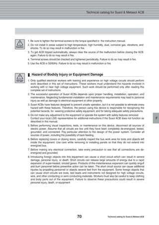
Installation and Service Condition
4. Service Condition
Fixed [H]
50
150
Draw out [H]
50
0
Note1) High Capacity(H type) Draw-Out type : Arc Space Zero(Option)
Fixed [N /S / H]Type
A
B
50
150
Draw out [N /S] Draw out [H]
Note1)
Note1)
8mm
14mm](https://image.slidesharecdn.com/metasolsusolacbtechnical201210-161116085854/85/Catalog-Metasol-Susol-ACB-LS-technical-77-320.jpg)
![88 Technical catalog for Susol & Metasol ACB
Technical catalog for Susol & Metasol ACB
H
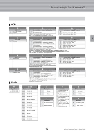
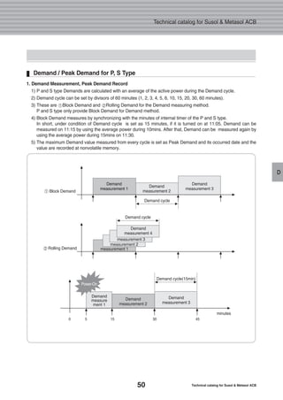
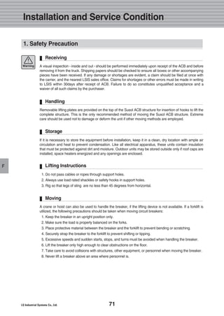
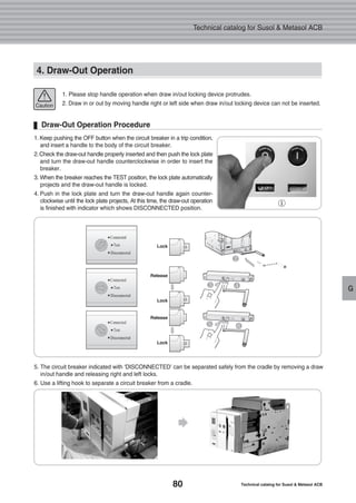
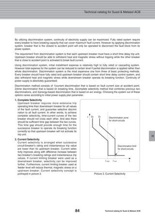
3. Discrimination Table
Main Breaker : Susol ACB / Branch Breaker : Susol MCCB
Below protective coordination table is based on ACB equipped with OCR under arrangement of short time delay
trip current as 10 times of rated current.
Note) 1. On table, protective coordination is not available for areas where number is missing.
2. On table, marked number is breaking capacity limit (Unit : KA) for protective coordination.
3. On table, areas that is marked as T are capable of total discrimination up to its branch breaker’s rated short breaking capacity.
Rated Voltage : AC 220/240V
TD100N 100 85
TD100H 100 100
TD100L 100 200
TD160N 160 85
TD160H 160 100
TD160L 160 200
TS100N 100 100
TS100H 100 120
TS100L 100 200
TS160N 160 100
TS160H 160 120
TS160L 160 200
TS250N 250 100
TS250H 250 120
TS250L 250 200
TS400N 400 100
TS400H 400 120
TS400L 400 200
TS630N 630 100
500
630
500
630
700
800
700
800
700
800
TS630H 120
TS630L 200
TS800N 100
TS800H 120
TS800L 200
Susol AH Series
AH-D, W
AH-06D AH-08D AH-06E
AH-
10D
AH-
13D
AH-
16D
AH-
20D
AH-
08E
AH-
10E
AH-
13E
AH-
16E
AH-
20E
AH-
25E
AH-
32E
AH-
40G
AH-
50G
AH-
63G
AH-
40E
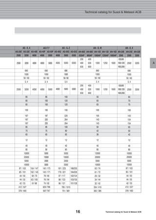
AH-E, X AH-G, Z
200 400 630 400 630 800 1,000 1,250 1,600 2,000 400 630
2 4 6.3 4 6.3 8 10 12.5 16 20 4 6.3
800 1,000 1,250 1,600 2,000 2,500 3,200 4,000 4,000 5,000 6,300
8 10 12.5 16 20 25 32 40 40 50 63
- 4 9 4 9 17 29 50 T T 4 9 17 29 50 T T T T T
- 4 9 4 9 17 29 50 85 T 4 9 17 29 50 85 T T T T
- 4 9 4 9 17 29 50 85 180 4 9 17 29 50 85 180 T T T
- 4 9 4 9 17 29 50 T T 4 9 17 29 50 T T T T T
- 4 9 4 9 17 29 50 85 T 4 9 17 29 50 85 T T T T
- 4 9 4 9 17 29 50 85 180 4 9 17 29 50 85 180 T T T
- 4 7 4 7 12 20 35 60 T 4 7 12 20 35 60 T T T T
- 4 7 4 7 12 20 35 60 100 4 7 12 20 35 60 100 T T T
- 4 7 4 7 12 20 35 60 100 4 7 12 20 35 60 100 T T T
- 4 7 4 7 12 20 35 60 T 4 7 12 20 35 60 T T T T
- 4 7 4 7 12 20 35 60 100 4 7 12 20 35 60 100 T T T
- 4 7 4 7 12 20 35 60 100 4 7 12 20 35 60 100 T T T
- 4 7 4 7 12 20 35 60 T 4 7 12 20 35 60 T T T T
- 4 7 4 7 12 20 35 60 100 4 7 12 20 35 60 100 T T T
- 4 7 4 7 12 20 35 60 100 4 7 12 20 35 60 100 T T T
- - - - - 8 10 12.5 16 20 - - 8 10 12.5 16 20 30 50 T
- - - - - 8 10 12.5 16 20 - - 8 10 12.5 16 20 30 50 T
- - - - - 8 10 12.5 16 20 - - 8 10 12.5 16 20 30 50 120
- - - - - 8 10 12.5 16 20 - - 8 10 12.5 16 20 30 50 T
- - - - - 8 10 12.5 16 20 - - 8 10 12.5 16 20 30 50 T
- - - - - 8 10 12.5 16 20 - - 8 10 12.5 16 20 30 50 T
- - - - - 8 10 12.5 16 20 - - 8 10 12.5 16 20 30 50 120
- - - - - 8 10 12.5 16 20 - - 8 10 12.5 16 20 30 50 120
- - - - - - 10 12.5 16 20 - - - 10 12.5 16 20 25 32 50
- - - - - - 10 12.5 16 20 - - - 10 12.5 16 20 25 32 50
- - - - - - 10 12.5 16 20 - - - 10 12.5 16 20 25 32 50
- - - - - - 10 12.5 16 20 - - - 10 12.5 16 20 25 32 50
- - - - - - 10 12.5 16 20 - - - 10 12.5 16 20 25 32 50
- - - - - - 10 12.5 16 20 - - - 10 12.5 16 20 25 32 50
T T T
T T T
T T T
T T T
T T T
T T T
T T T
T T T
T T T
T T T
T T T
T T T
T T T
T T T
T T T
T T T
T T T
120 T T
T T T
T T T
T T T
120 T T
120 T T
50 T T
50 T T
50 T T
50 T T
50 120 T
50 120 T
85 100 150
SusolMCCB
Model
Rated
Current
[A]
Rated
Current[A]
Short Time
Delay Trip
Current
(Max. 10In)
Is[kA]
Product
Type
Upstream
Breaker
Branch
Breaker
Ultimate
Breaking
Capacity
Icu[kA]](https://image.slidesharecdn.com/metasolsusolacbtechnical201210-161116085854/85/Catalog-Metasol-Susol-ACB-LS-technical-90-320.jpg)
![89
H
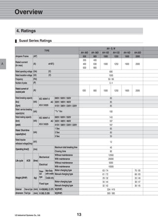
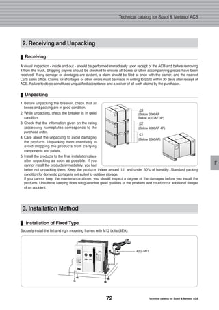
Protective Coordination
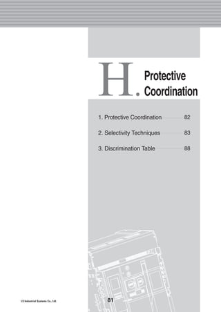
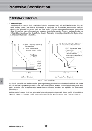
3. Discrimination Table
Main Breaker : Susol ACB / Branch Breaker : Susol MCCB
Below protective coordination table is based on ACB equipped with OCR under arrangement of short time delay
trip current as 10 times of rated current.
Note) 1. On table, protective coordination is not available for areas where number is missing.
2. On table, marked number is breaking capacity limit (Unit : KA) for protective coordination.
3. On table, areas that is marked as T are capable of total discrimination up to its branch breaker’s rated short breaking capacity.
Rated Voltage : AC 380/415V
TD100N 100 50
TD100H 100 85
TD100L 100 150
TD160N 160 50
TD160H 160 85
TD160L 160 150
TS100N 100 50
TS100H 100 85
TS100L 100 150
TS160N 160 50
TS160H 160 85
TS160L 160 150
TS250N 250 50
TS250H 250 85
TS250L 250 150
TS400N 400 65
TS400H 400 85
TS400L 400 150
TS630N 630 65
500
630
500
630
700
800
700
800
700
800
TS630H 85
TS630L 150
TS800N 65
TS800H 100
TS800L 150
Susol AH Series
AH-D, W
AH-06D AH-08D AH-06E
AH-
10D
AH-
13D
AH-
16D
AH-
20D
AH-
08E
AH-
10E
AH-
13E
AH-
16E
AH-
20E
AH-
25E
AH-
32E
AH-
40G
AH-
50G
AH-
63G
AH-
40E
AH-E, X AH-G, Z
200 400 630 400 630 800 1,000 1,250 1,600 2,000 400 630
2 4 6.3 4 6.3 8 10 12.5 16 20 4 6.3
800 1,000 1,250 1,600 2,000 2,500 3,200 4,000 4,000 5,000 6,300
8 10 12.5 16 20 25 32 40 40 50 63
- 4 6.3 4 6.3 9 13.5 22 38 T 4 6.3 9 13.5 22 38 T T T T
- 4 6.3 4 6.3 9 13.5 22 38 60 4 6.3 9 13.5 22 38 60 T T T
- 4 6.3 4 6.3 9 13.5 22 38 60 4 6.3 9 13.5 22 38 60 120 T T
- 4 6.3 4 6.3 9 13.5 22 38 T 4 6.3 9 13.5 22 38 T T T T
- 4 6.3 4 6.3 9 13.5 22 38 60 4 6.3 9 13.5 22 38 60 T T T
- 4 6.3 4 6.3 9 13.5 22 38 60 4 6.3 9 13.5 22 38 60 120 T T
- 4 6.3 4 6.3 8 10 15 26 43 4 6.3 8 10 15 26 43 T T T
- 4 6.3 4 6.3 8 10 15 26 43 4 6.3 8 10 15 26 43 70 T T
- 4 6.3 4 6.3 8 10 15 26 43 4 6.3 8 10 15 26 43 70 120 T
- 4 6.3 4 6.3 8 10 15 26 43 4 6.3 8 10 15 26 43 T T T
- 4 6.3 4 6.3 8 10 15 26 43 4 6.3 8 10 15 26 43 70 T T
- 4 6.3 4 6.3 8 10 15 26 43 4 6.3 8 10 15 26 43 70 120 T
- 4 6.3 4 6.3 8 10 15 26 43 4 6.3 8 10 15 26 43 T T T
- 4 6.3 4 6.3 8 10 15 26 43 4 6.3 8 10 15 26 43 70 T T
- 4 6.3 4 6.3 8 10 15 26 43 4 6.3 8 10 15 26 43 70 120 T
- - - - - 8 10 12.5 16 20 - - 8 10 12.5 16 20 25 35 T
- - - - - 8 10 12.5 16 20 - - 8 10 12.5 16 20 25 35 65
- - - - - 8 10 12.5 16 20 - - 8 10 12.5 16 20 25 35 65
- - - - - 8 10 12.5 16 20 - - 8 10 12.5 16 20 25 35 T
- - - - - 8 10 12.5 16 20 - - 8 10 12.5 16 20 25 35 65
- - - - - 8 10 12.5 16 20 - - 8 10 12.5 16 20 25 35 65
- - - - - 8 10 12.5 16 20 - - 8 10 12.5 16 20 25 35 65
- - - - - 8 10 12.5 16 20 - - 8 10 12.5 16 20 25 35 65
- - - - - - 10 12.5 16 20 - - - 10 12.5 16 20 25 32 40
- - - - - - 10 12.5 16 20 - - - 10 12.5 16 20 25 32 40
- - - - - - 10 12.5 16 20 - - - 10 12.5 16 20 25 32 40
- - - - - - 10 12.5 16 20 - - - 10 12.5 16 20 25 32 40
- - - - - - 10 12.5 16 20 - - - 10 12.5 16 20 25 32 40
- - - - - - 10 12.5 16 20 - - - 10 12.5 16 20 25 32 40
T T T
T T T
T T T
T T T
T T T
T T T
T T T
T T T
T T T
T T T
T T T
T T T
T T T
T T T
T T T
T T T
65 T T
65 130 T
T T T
65 T T
65 T T
65 130 T
65 130 T
40 T T
40 T T
40 65 T
40 65 T
40 65 110
40 65 110
85 100 150
SusolMCCB
Model
Rated
Current
[A]
Rated
Current[A]
Short Time
Delay Trip
Current
(Max. 10In)
Is[kA]
Product
Type
Upstream
Breaker
Branch
Breaker
Ultimate
Breaking
Capacity
Icu[kA]](https://image.slidesharecdn.com/metasolsusolacbtechnical201210-161116085854/85/Catalog-Metasol-Susol-ACB-LS-technical-91-320.jpg)
![90 Technical catalog for Susol & Metasol ACB
Technical catalog for Susol & Metasol ACB
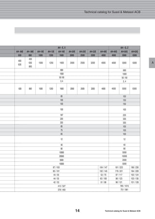
H
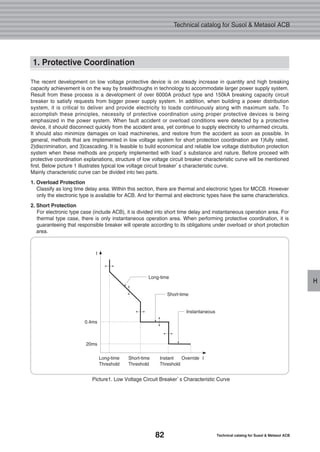
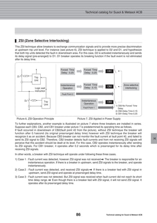
Main Breaker : Susol ACB / Branch Breaker : Susol MCCB
Below protective coordination table is based on ACB equipped with OCR under arrangement of short time delay
trip current as 10 times of rated current.
Note) 1. On table, protective coordination is not available for areas where number is missing.
2. On table, marked number is breaking capacity limit (Unit : KA) for protective coordination.
3. On table, areas that is marked as T are capable of total discrimination up to its branch breaker’s rated short breaking capacity.
Rated Voltage : AC 480/500V
TD100N 100 30
TD100H 100 50
TD100L 100 65
TD160N 160 30
TD160H 160 50
TD160L 160 65
TS100N 100 42
TS100H 100 65
TS100L 100 85
TS160N 160 42
TS160H 160 65
TS160L 160 85
TS250N 250 42
TS250H 250 65
TS250L 250 85
TS400N 400 42
TS400H 400 65
TS400L 400 85
TS630N 630 42
500
630
500
630
700
800
700
800
700
800
TS630H 65
TS630L 85
TS800N 42
TS800H 85
TS800L 100
Susol AH Series
AH-D, W
AH-06D AH-08D AH-06E
AH-
10D
AH-
13D
AH-
16D
AH-
20D
AH-
08E
AH-
10E
AH-
13E
AH-
16E
AH-
20E
AH-
25E
AH-
32E
AH-
40G
AH-
50G
AH-
63G
AH-
40E
AH-E, X AH-G, Z
200 400 630 400 630 800 1,000 1,250 1,600 2,000 400 630
2 4 6.3 4 6.3 8 10 12.5 16 20 4 6.3
800 1,000 1,250 1,600 2,000 2,500 3,200 4,000 4,000 5,000 6,300
8 10 12.5 16 20 25 32 40 40 50 63
- 4 6.3 4 6.3 8 10 17 T T 4 6.3 8 10 17 T T T T T
- 4 6.3 4 6.3 8 10 17 30 T 4 6.3 8 10 17 30 T T T T
- 4 6.3 4 6.3 8 10 17 30 55 4 6.3 8 10 17 30 55 T T T
- 4 6.3 4 6.3 8 10 17 T T 4 6.3 8 10 17 T T T T T
- 4 6.3 4 6.3 8 10 17 30 T 4 6.3 8 10 17 30 T T T T
- 4 6.3 4 6.3 8 10 17 30 55 4 6.3 8 10 17 30 55 T T T
- 4 6.3 4 6.3 8 10 14 25 T 4 6.3 8 10 14 25 T T T T
- 4 6.3 4 6.3 8 10 14 25 42.5 4 6.3 8 10 14 25 42.5 T T T
- 4 6.3 4 6.3 8 10 14 25 42.5 4 6.3 8 10 14 25 42.5 70 T T
- 4 6.3 4 6.3 8 10 14 25 T 4 6.3 8 10 14 25 T T T T
- 4 6.3 4 6.3 8 10 14 25 42.5 4 6.3 8 10 14 25 42.5 T T T
- 4 6.3 4 6.3 8 10 14 25 42.5 4 6.3 8 10 14 25 42.5 70 T T
- 4 6.3 4 6.3 8 10 14 25 T 4 6.3 8 10 14 25 T T T T
- 4 6.3 4 6.3 8 10 14 25 42.5 4 6.3 8 10 14 25 42.5 T T T
- 4 6.3 4 6.3 8 10 14 25 42.5 4 6.3 8 10 14 25 42.5 70 T T
- - - - - 8 10 12.5 16 20 - - 8 10 12.5 16 20 25 32 T
- - - - - 8 10 12.5 16 20 - - 8 10 12.5 16 20 25 32 52.5
- - - - - 8 10 12.5 16 20 - - 8 10 12.5 16 20 25 32 52.5
- - - - - 8 10 12.5 16 20 - - 8 10 12.5 16 20 25 32 T
- - - - - 8 10 12.5 16 20 - - 8 10 12.5 16 20 25 32 52.5
- - - - - 8 10 12.5 16 20 - - 8 10 12.5 16 20 25 32 52.5
- - - - - 8 10 12.5 16 20 - - 8 10 12.5 16 20 25 32 52.5
- - - - - 8 10 12.5 16 20 - - 8 10 12.5 16 20 25 32 52.5
- - - - - - 10 12.5 16 20 - - - 10 12.5 16 20 25 32 40
- - - - - - 10 12.5 16 20 - - - 10 12.5 16 20 25 32 40
- - - - - - 10 12.5 16 20 - - - 10 12.5 16 20 25 32 40
- - - - - - 10 12.5 16 20 - - - 10 12.5 16 20 25 32 40
- - - - - - 10 12.5 16 20 - - - 10 12.5 16 20 25 32 40
- - - - - - 10 12.5 16 20 - - - 10 12.5 16 20 25 32 40
T T T
T T T
T T T
T T T
T T T
T T T
T T T
T T T
T T T
T T T
T T T
T T T
T T T
T T T
T T T
T T T
52.5 T T
52.5 T T
T T T
52.5 T T
52.5 T T
52.5 T T
52.5 T T
40 T T
40 T T
40 55 T
40 55 T
40 55 90
40 55 90
85 100 150
SusolMCCB
Model
Rated
Current
[A]
Rated
Current[A]
Short Time
Delay Trip
Current
(Max. 10In)
Is[kA]
Product
Type
Upstream
Breaker
Branch
Breaker
Ultimate
Breaking
Capacity
Icu[kA]](https://image.slidesharecdn.com/metasolsusolacbtechnical201210-161116085854/85/Catalog-Metasol-Susol-ACB-LS-technical-92-320.jpg)
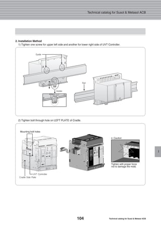
![103
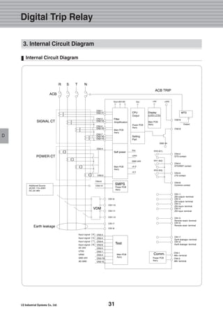
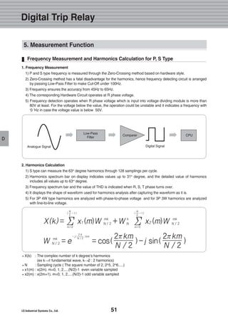
Accessories
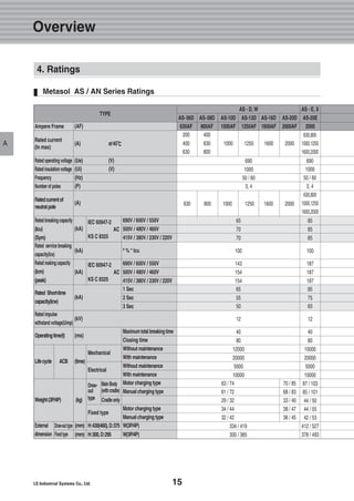
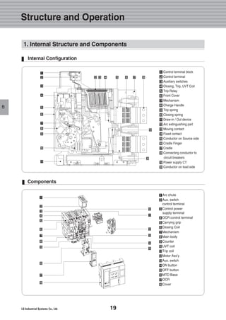
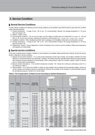
I
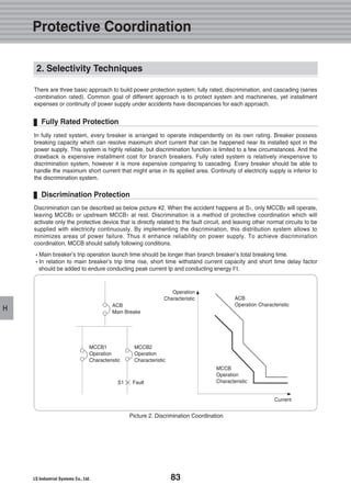
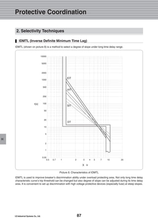
It is a device which makes ACB tripped automatically to prevent the accident on load side due to under voltage or
power breakdown. There are two types, Instantaneous type and time delay type.
1. Externals 2. Wring Diagram
Note) Operating voltage range is the min. rated standard for each rated voltage (Vh).
Rated Voltage[Vn] Operating Voltage Range[V] Power Consumption[VA or W]
Pick-up Drop-out Inrush Steady-state
0.65 ~ 0.85 Vn 0.4 ~ 0.65 Vn 200 5
DC[V] AC[V]
48~60 48
100~130 100~130
200~250 200~250
- 380~480
Trip Time
[S]
0.5, 1, 1.5, 3
UVT Time Delay Controller
UVT DELAY
CONTROLLER
UVT
Delay Trip
Command
Instaneous
Trip
Command
Operating 18(a)
Output 19(c)
Contact 20(b)
5 7
14
D1
D2
16
3. External Mounting](https://image.slidesharecdn.com/metasolsusolacbtechnical201210-161116085854/85/Catalog-Metasol-Susol-ACB-LS-technical-105-320.jpg)
![129
J
1. Transporting and Storage
Fig 1. Lifting by forklift
�When lifting products with forklift, be careful with the bottom plane not to be beyond the rear side of products.
(Refer to fig.1)
This breaker and cradle are designed to move easily by overhead lifting devices such as hoisters. You can use lifting
hooks which is optional to move them without difficulty. All the carrying devices should be suited to the product’s
permissible weight which is presented in Table.1. In case of using forklift, refer to figure.1.
Type
2,000AF 4,000AF
Fixed Type
Draw-out Type
Cradle
Draw-in/Out
Load
[kgf.cm]
3P
34
63
29
60/35
4P
44
74
32
70/45
3P
38
70
33
70/45
4P
47
85
40
80/50
3P
44
87
44
105/54
4P
55
103
50
110/55
3P
63
104
58
125/58
4P
100
147
70
135/60
3P
76
145
78
160/65
4P
94
173
90
170/70
3P
103
186
102
190/75
4P
130
230
124
195/85
1,600A 2,000A 3,000A
5,000AF 6,300AF
4,000A [Fork-Type]
Handling and Maintenance
[Based on kgf, IEC]](https://image.slidesharecdn.com/metasolsusolacbtechnical201210-161116085854/85/Catalog-Metasol-Susol-ACB-LS-technical-131-320.jpg)
![138 Technical catalog for Susol & Metasol ACB
Technical catalog for Susol & Metasol ACB
K
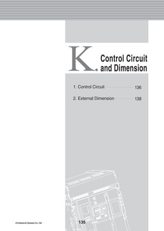
2. External Dimension
Fixed Type 2000AF (630A~1600A)
Front View [3P] Front View [4P] Conductor
■■ Horizontal Type(3P Plan View) ■■ Horizontal Type(4P Plan View) ■■ Horizontal Type(Side View)
■■ Vertical Type(3P Plan View) ■■ Vertical Type(4P Plan View) ■■ Vertical Type(Side View)
■■ Front Connection Type(3P Plan View) ■■ Front Connection Type(4P Plan View) ■■ Front Connection Type(Side View)](https://image.slidesharecdn.com/metasolsusolacbtechnical201210-161116085854/85/Catalog-Metasol-Susol-ACB-LS-technical-140-320.jpg)
![139
K
Draw-out Type 2000AF (630A~1600A)
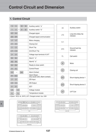
Control Circuit and Dimension
Front View [3P] Front View [4P] Conductor
■■ Horizontal Type(3P Plan View) ■■ Horizontal Type(4P Plan View) ■■ Horizontal Type(Side View)
■■ Vertical Type(3P Plan View) ■■ Vertical Type(4P Plan View) ■■ Vertical Type(Side View)
■■ Front Connection Type(3P Plan View) ■■ Front Connection Type(4P Plan View) ■■ Front Connection Type(Side View)
2. External Dimension](https://image.slidesharecdn.com/metasolsusolacbtechnical201210-161116085854/85/Catalog-Metasol-Susol-ACB-LS-technical-141-320.jpg)
![140 Technical catalog for Susol & Metasol ACB
Technical catalog for Susol & Metasol ACB
K
Fixed Type 2000AF (2000A)
■■ Horizontal Type(3P Plan View) ■■ Horizontal Type(4P Plan View) ■■ Horizontal Type(Side View)
■■ Front Connection Type(3P Plan View) ■■ Front Connection Type(4P Plan View) ■■ Front Connection Type(Side View)
Front View [3P] Front View [4P] Conductor](https://image.slidesharecdn.com/metasolsusolacbtechnical201210-161116085854/85/Catalog-Metasol-Susol-ACB-LS-technical-142-320.jpg)
![141
K
Draw-out type 2000AF (2000A)
Control Circuit and Dimension
■■ Horizontal Type(3P Plan View) ■■ Horizontal Type(4P Plan View) ■■ Horizontal Type(Side View)
■■ Front Connection Type(3P Plan View) ■■ Front Connection Type(4P Plan View) ■■ Front Connection Type(Side View)
Front View [3P] Front View [4P] Conductor
2. External Dimension](https://image.slidesharecdn.com/metasolsusolacbtechnical201210-161116085854/85/Catalog-Metasol-Susol-ACB-LS-technical-143-320.jpg)
![142 Technical catalog for Susol & Metasol ACB
Technical catalog for Susol & Metasol ACB
K
Fixed Type 4000AF (630A~3200A)
75
■■ Horizontal Type(3P Plan View) ■■ Horizontal Type(4P Plan View) ■■ Horizontal Type(Side View)
■■ Vertical Type(3P Plan View) ■■ Vertical Type(4P Plan View) ■■ Vertical Type(Side View)
■■ Front Connection Type(3P Plan View) ■■ Front Connection Type(4P Plan View) ■■ Front Connection Type(Side View)
Front View [3P] Front View [4P] Conductor](https://image.slidesharecdn.com/metasolsusolacbtechnical201210-161116085854/85/Catalog-Metasol-Susol-ACB-LS-technical-144-320.jpg)
![143
K
Draw-out Type 4000AF (630A~3200A)
Control Circuit and Dimension
■■ Horizontal Type(3P Plan View) ■■ Horizontal Type(4P Plan View) ■■ Horizontal Type(Side View)
■■ Vertical Type(3P Plan View) ■■ Vertical Type(4P Plan View) ■■ Vertical Type(Side View)
■■ Front Connection Type(3P Plan View) ■■ Front Connection Type(4P Plan View) ■■ Front Connection Type(Side View)
Front View [3P] Front View [4P] Conductor
2. External Dimension](https://image.slidesharecdn.com/metasolsusolacbtechnical201210-161116085854/85/Catalog-Metasol-Susol-ACB-LS-technical-145-320.jpg)
![144 Technical catalog for Susol & Metasol ACB
Technical catalog for Susol & Metasol ACB
K
Fixed Type 4000AF (4000A)
12.512.59.5
■■ Horizontal Type(3P Plan View) ■■ Horizontal Type(4P Plan View) ■■ Horizontal Type(Side View)
■■ Vertical Type(3P Plan View) ■■ Vertical Type(4P Plan View) ■■ Vertical Type(Side View)
Front View [3P] Front View [4P] Conductor](https://image.slidesharecdn.com/metasolsusolacbtechnical201210-161116085854/85/Catalog-Metasol-Susol-ACB-LS-technical-146-320.jpg)
![145
K
Draw-out Type 4000AF (4000A)
Control Circuit and Dimension
■■ Horizontal Type(3P Plan View) ■■ Horizontal Type(4P Plan View) ■■ Horizontal Type(Side View)
■■ Vertical Type(3P Plan View) ■■ Vertical Type(4P Plan View) ■■ Vertical Type(Side View)
Front View [3P] Front View [4P] Conductor
2. External Dimension
140
100 12.5
260
412
140
200115
OPERATING PANEL CENTER](https://image.slidesharecdn.com/metasolsusolacbtechnical201210-161116085854/85/Catalog-Metasol-Susol-ACB-LS-technical-147-320.jpg)
![146 Technical catalog for Susol & Metasol ACB
Technical catalog for Susol & Metasol ACB
K
Fixed Type 5000AF
■■ Horizontal Type(3P Plan View) ■■ Horizontal Type(4P Plan View) ■■ Horizontal Type(Side View)
■■ Vertical Type(3P Plan View) ■■ Vertical Type(4P Plan View) ■■ Vertical Type(Side View)
Front View [3P] Front View [4P] Conductor](https://image.slidesharecdn.com/metasolsusolacbtechnical201210-161116085854/85/Catalog-Metasol-Susol-ACB-LS-technical-148-320.jpg)
![147
K
Draw-out Type 5000AF
Control Circuit and Dimension
■■ Horizontal Type(3P Plan View) ■■ Horizontal Type(4P Plan View) ■■ Horizontal Type(Side View)
■■ Vertical Type(3P Plan View) ■■ Vertical Type(4P Plan View) ■■ Vertical Type(Side View)
Front View [3P] Front View [4P] Conductor
2. External Dimension](https://image.slidesharecdn.com/metasolsusolacbtechnical201210-161116085854/85/Catalog-Metasol-Susol-ACB-LS-technical-149-320.jpg)
![148 Technical catalog for Susol & Metasol ACB
Technical catalog for Susol & Metasol ACB
K
Fixed Type 6300AF (4000~6300A)
■■ Horizontal Type(3P Plan View) ■■ Horizontal Type(4P Plan View) ■■ Horizontal Type(Side View)
■■ Vertical Type(3P Plan View) ■■ Vertical Type(4P Plan View) ■■ Vertical Type(Side View)
Front View [3P] Front View [4P] Conductor](https://image.slidesharecdn.com/metasolsusolacbtechnical201210-161116085854/85/Catalog-Metasol-Susol-ACB-LS-technical-150-320.jpg)
![149
K
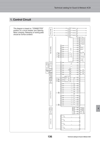
Draw-out Type 6300AF(4000~6300A)
Control Circuit and Dimension
Panel Cutting Dimension
CRADLE BOTTOM
�D, E = 170 / F, G = 200
165 165
120120
170(200)
128
OPERATING PANEL CENTER
315(PANEL CUTTING DIMENSION)
353(PANELCUTTINGDIMENSION)
10 - 5
■■Common use for all types
■■ Horizontal Type(3P Plan View) ■■ Horizontal Type(4P Plan View) ■■ Horizontal Type(Side View)
■■ Vertical Type(3P Plan View) ■■ Vertical Type(4P Plan View) ■■ Vertical Type(Side View)
Front View [3P] Front View [4P] Conductor
2. External Dimension](https://image.slidesharecdn.com/metasolsusolacbtechnical201210-161116085854/85/Catalog-Metasol-Susol-ACB-LS-technical-151-320.jpg)


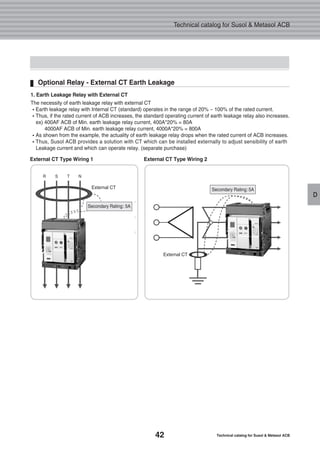
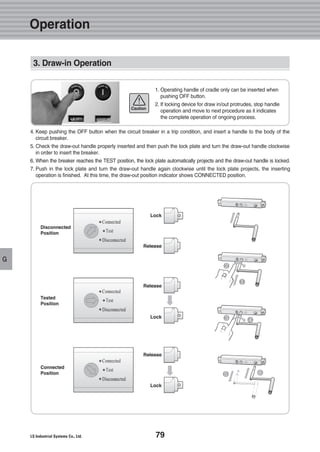
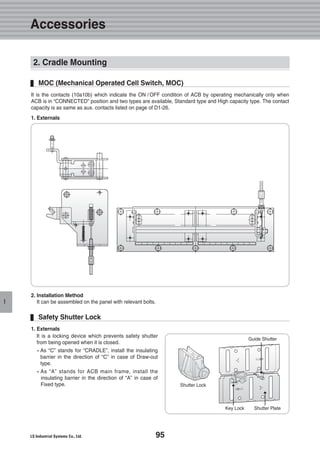
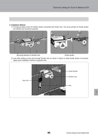
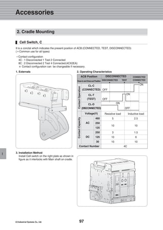
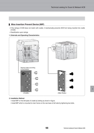
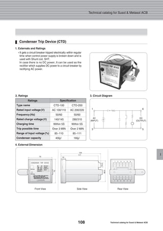
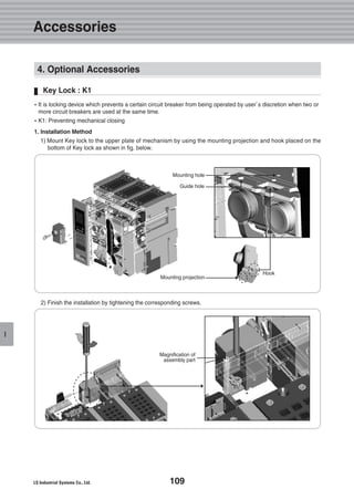
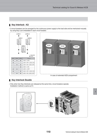
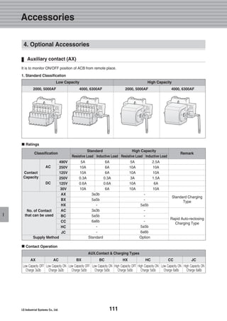
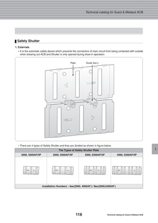
The document is a technical catalog for the Susol and Metasol air circuit breakers (ACBs), detailing product specifications, structure, operation, and accessories. It emphasizes features designed to meet high breaking capacities and customer needs, along with compliance to international standards. Additionally, it provides guidelines for installation, maintenance, and product ordering procedures.


