Download to read offline


![55
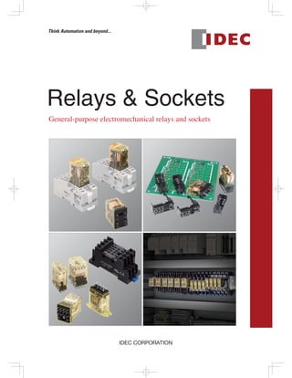
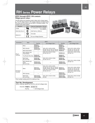
RF1V Force Guided Relays
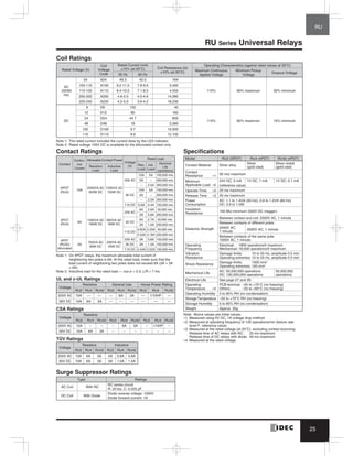
Specifications
Number of Poles 4-pole 6-pole
Contact Configuration 2NO-2NC 3NO-1NC 4NO-2NC 5NO-1NC 3NO-3NC
Contact Resistance (initial value) (Note 1) 100 mΩ maximum
Contact Material AgSnO2 (Au flashed)
Rated Load (resistive load) 6A 250V AC, 6A 30V DC
Allowable Switching Power (resistive load) 1500 VA, 180W
Allowable Switching Voltage 250V AC, 125V DC
Allowable Switching Current 6A
Minimum Applicable Load (Note 2) 5V DC, 1 mA (reference value)
Power Consumption (approx.) 0.36W 0.5W
Insulation Resistance
1000 MΩ minimum (500V DC megger, same measurement positions as the
dielectric strength)
Dielectric
Strength
Between contact and coil 4000V AC, 1 minute
Between contacts of different poles
2500V AC, 1 minute
Between contacts 7-8 and 9-10
2500V AC, 1 minute
Between contacts 7-8 and 11-12
Between contacts 9-10 and 13-14
Between contacts 11-12 and 13-14
4000V AC, 1 min.
Between contacts 3-4 and 5-6
Between contacts 3-4 and 7-8
Between contacts 5-6 and 9-10
4000V AC, 1 min.
Between contacts 3-4 and 5-6
Between contacts 3-4 and 7-8
Between contacts 5-6 and 9-10
Between contacts 7-8 and 9-10
Between contacts of the same pole 1500V AC, 1 minute
Operate Time (at 20°C) 20 ms maximum (at the rated coil voltage, excluding contact bounce time)
Response Time (at 20°C) (Note 3) 8 ms maximum (at the rated coil voltage, excluding contact bounce time)
Release Time (at 20°C) 20 ms maximum (at the rated coil voltage, excluding contact bounce time)
Vibration
Resistance
Operating Extremes 10 to 55 Hz, amplitude 0.75 mm
Damage Limits 10 to 55 Hz, amplitude 0.75 mm
Shock
Resistance
Operating Extremes (half sine-wave pulse: 11 ms) 200 m/s2
, when mounted on DIN rail mount socket: 150 m/s2
Damage Limits (half sine-wave pulse: 6 ms) 1000 m/s2
Electrical Life
250V AC 6A resistive load: 100,000 operations minimum (operating frequency
1200 per hour)
30V DC 6A resistive load: 100,000 operations minimum (operating frequency
1200 per hour)
250V AC 1A resistive load: 500,000 operations minimum (operating frequency
1800 per hour)
30V DC 1A resistive load: 500,000 operations minimum (operating frequency
1800 per hour)
[AC 15] 240V AC 2A inductive load: 100,000 operations minimum
(operating frequency 1200 per hour, cos ø = 0.3)
[DC 13] 24V DC 1A inductive load: 100,000 operations minimum
(operating frequency 1200 per hour, L/R = 48 ms)
Mechanical Life 10 million operations minimum (operating frequency 10,800 operations per hour)
Operating Temperature (Note 4) –40 to +85°C (no freezing)
Storage Temperature –40 to +85°C (no freezing)
Operating Humidity 5 to 85% RH (no condensation)
Storage Humidity 5 to 85% RH (no condensation)
Operating Frequency (rated load) 1200 operations per hour
Weight (approx.) 20g 23g
Note 1: Measured using 6V DC,1A voltage drop method.
Note 2: Failure rate level P, 1/10,000,000 (reference value) (JIS C5003)
Note 3: Response time is the time until NO contact opens, after the coil voltage is turned off.
Note 4: When using at 70 to 85°C, reduce the switching current by 0.1A/°C.
RF1V](https://image.slidesharecdn.com/catalog-relay-idec-190822083232/85/Catalog-relay-idec-2019-56-320.jpg)


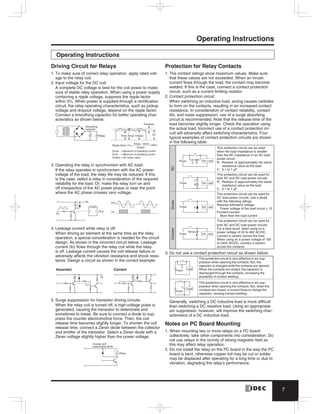
![87
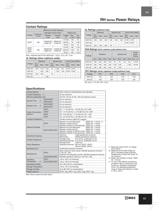
Relay Sockets
Panel Mount Sockets
SM Series
SM2S-51
SY Series
SY2S-51
SY4S-51
SH Series
SH1B-51
SH2B-51
3
11
18.7
27
31
0.3
25.4
2.4
21.2
13 14
1
5
9 12
8
4
Terminal Arrangement
25.6
0
+0.5
+0.2
0
10.4 min. when using hold-down springs
[27 (N–1) + 21.4]
5.4min.
N: No. of sockets mounted
Panel Thickness:
1 to 2
(Bottom View)
3
11
18.7
18
31
2.4
12.2
25.4
Panel Thickness:
1 to 2
13
1
5
9
14
4
8
12
Terminal Arrangement
10.4 min. when husing hold-down springs
+0.2
0
+0.5
0
[18(N–1)+12.4]
5.4min.25.6
N: No. of sockets mounted0.3 (Bottom View)
27
31
2.4
21.2
3
11
18.7
25.4
Panel Thickness:
1 to 2
10
7
13 14
1
5
9
3
12
8
4
6
2
11
Terminal Arrangement
25.6
0
+0.5
+0.2
0
10.4 min. when using hold-down springs
[27 (N–1) + 21.4]
5.4min.
N: No. of sockets mounted
0.3
(Bottom View)
3
11
18.7
18
31
2.4
12.2
0.3
25.4
3.5
Panel Thickness:
1 to 2
13
1
5
9
(Bottom View)
14
Terminal Arrangement
25.6
0
+0.5
+0.2
0
10.4 min. when using hold-down springs
5.4min.
N: No. of sockets mounted
[18 (N–1) + 12.4]
3
11
18.7
27
31
0.3
25.4
21.2
3.5
Panel Thickness:
1 to 2
13
1
5
9
4
12
8
14
Terminal Arrangement
25.6
+0.2
0
+0.5
0
10.4 min. when using hold-down springs
5.4min.
N: No. of sockets mounted
[27 (N–1) + 21.4]
(Bottom View)](https://image.slidesharecdn.com/catalog-relay-idec-190822083232/85/Catalog-relay-idec-2019-88-320.jpg)
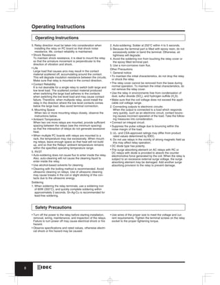
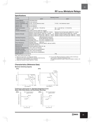
![88
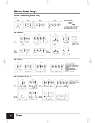
Relay Sockets
SH3B-51
SH4B-51
SR Series
SR2P-511
SR2P-70
SR3P-511
3
11
18.7
31
0.3
25.4
30.2
3.5
36
Panel Thickness:
1 to 2
Terminal Arrangement
13
1
5
9
2
10
6
14
4
12
8
25.6
+0.2
0
+0.5
0
∗ 10.4 min. when using hold-down springs
5.4min.∗
N: No. of sockets mounted
[36 (N–1) + 30.4]
(Bottom View)
3
11
18.7
31
0.3
25.4
39.2
45
3.5
Panel Thickness:
1 to 2
13
1
5
9
3
11
7
14
4
12
8
2
10
6
Terminal Arrangement
25.6
+0.2
0
+0.5
0
∗ 10.4 min. when using hold-down springs
5.4min.∗
N: No. of sockets mounted
[45 (N–1) + 39.4]
(Bottom View)
2.5
6
38
50
4.2
34 2.5 10 11
2-ø3.5 Mounting Holes
(or M3 Tapped Holes)
ø30
38
ø29
Panel
Surface
1
2
3
4 5
6
7
8
(Bottom View)
Terminal Arrangement
2.5
6
38
50
4.2
34 2.5 10
ø29
17.5
ø30
38
2-ø3.5 Mounting Holes
(or M3 Tapped Holes)
Panel
Surface
(Bottom View)
1
2
3
4 5
6
7
8
Terminal Arrangement
2.5
6
38
50
4.2
34 2.5 10 11
ø29
ø30
38
2-ø3.5 Mounting Holes
(or M3 Tapped Holes)
Panel
Surface
10
111
2
3
4
5 6 7
8
9
(Bottom View)
Terminal Arrangement](https://image.slidesharecdn.com/catalog-relay-idec-190822083232/85/Catalog-relay-idec-2019-89-320.jpg)


The document provides a detailed selection guide for various types of electromechanical relays and sockets, including specifications such as maximum capacity, rated load, coil voltage, and contact configurations. It includes a comparison of relay models with different contact materials, capacities, and applications, along with dimensions and operational characteristics. Additionally, it outlines applicable sockets and environmental considerations such as operating temperatures and humidity levels.