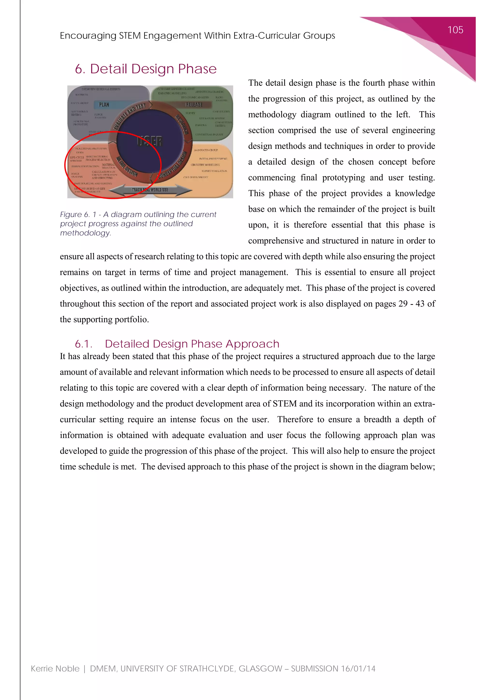
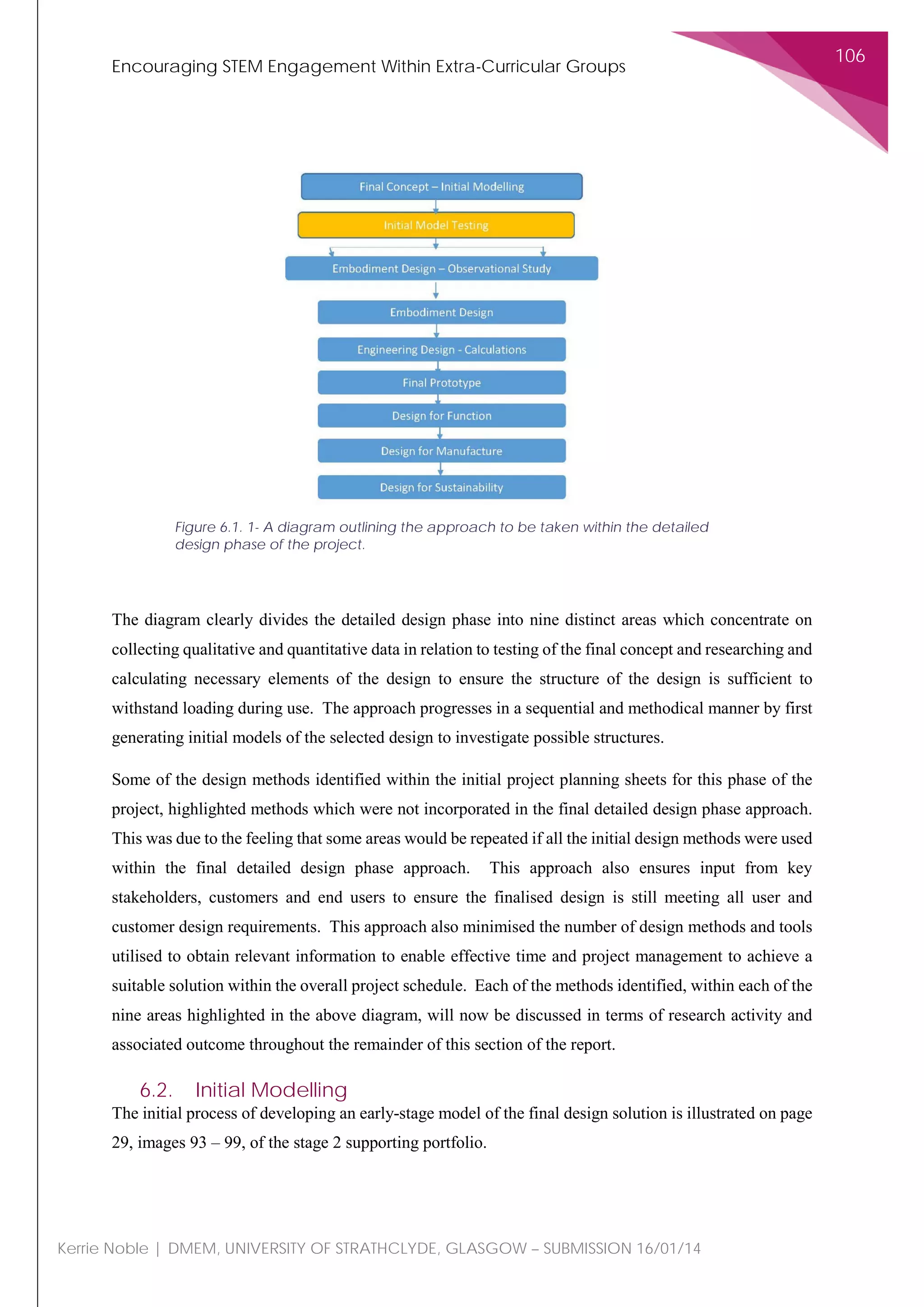
The document is a stage 2 report for an individual project that aims to encourage STEM engagement within extra-curricular groups. It provides an overview of the conceptual design phase where concepts were generated, evaluated, and refined. It also describes initial modeling and testing. The detailed design phase is discussed where embodiment design questions were considered and prototypes were developed and tested. The report outlines the progress made against the project methodology and provides documentation to support the design process.


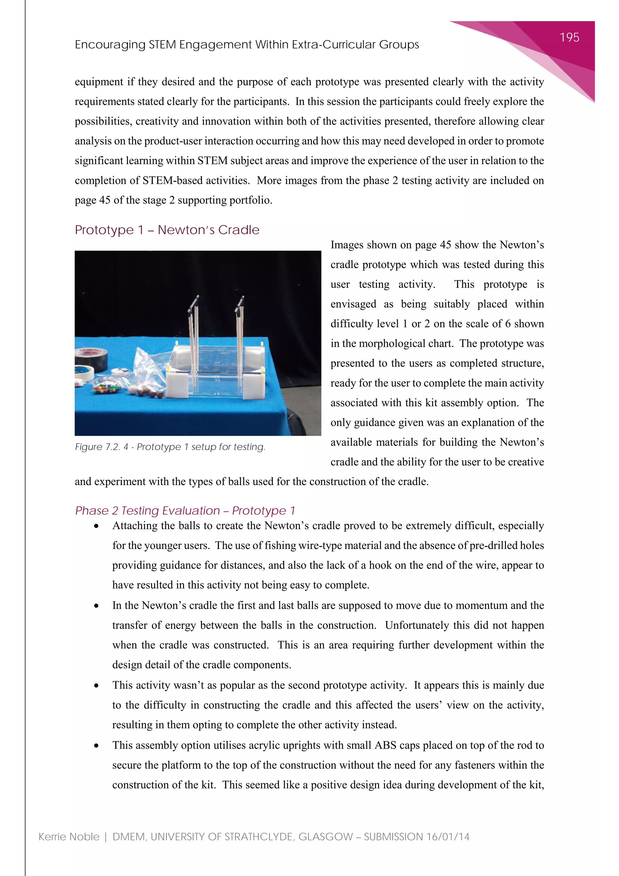
![Encouraging STEM Engagement Within Extra-Curricular Groups
119
Kerrie Noble | DMEM, UNIVERSITY OF STRATHCLYDE, GLASGOW – SUBMISSION 16/01/14
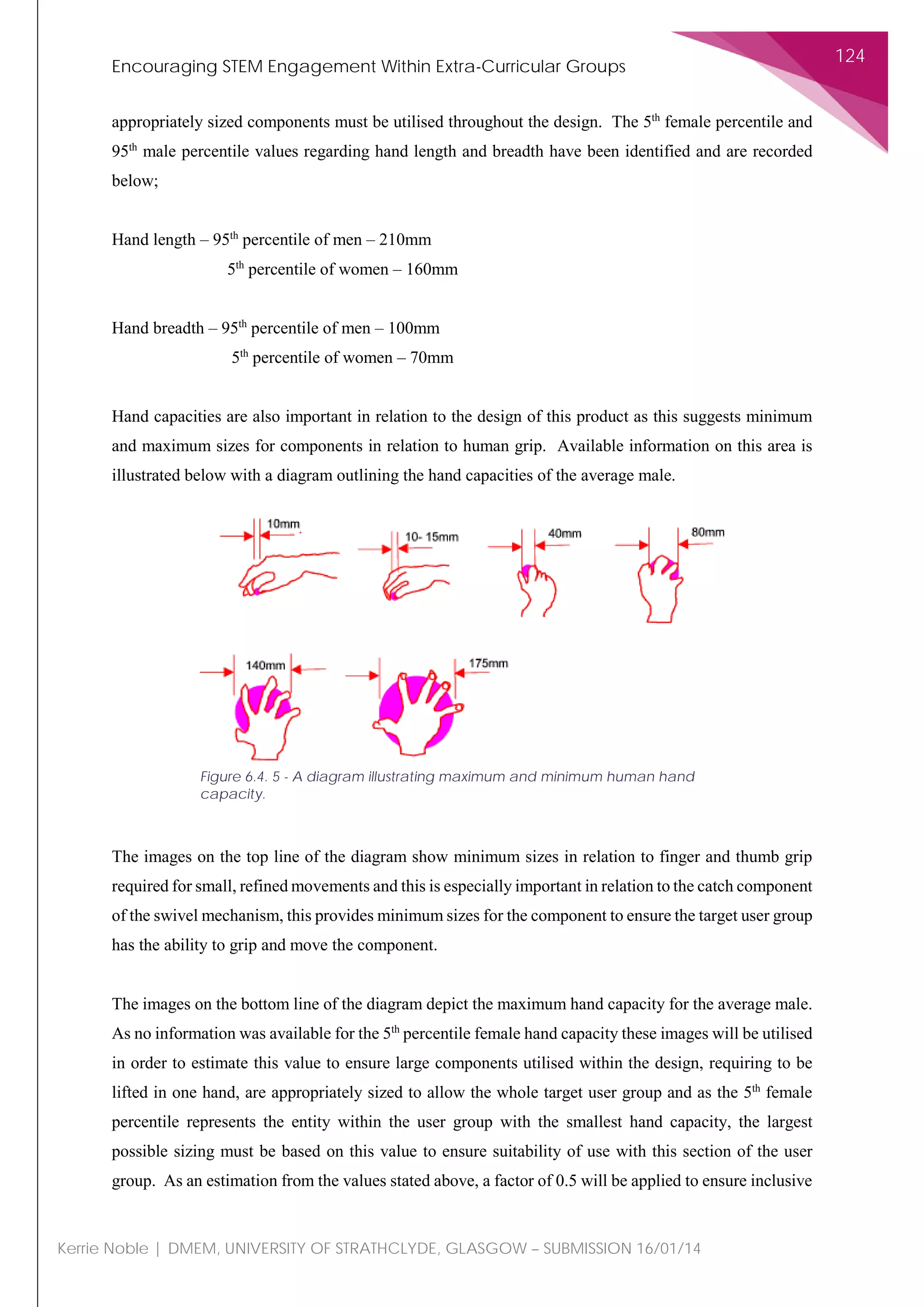
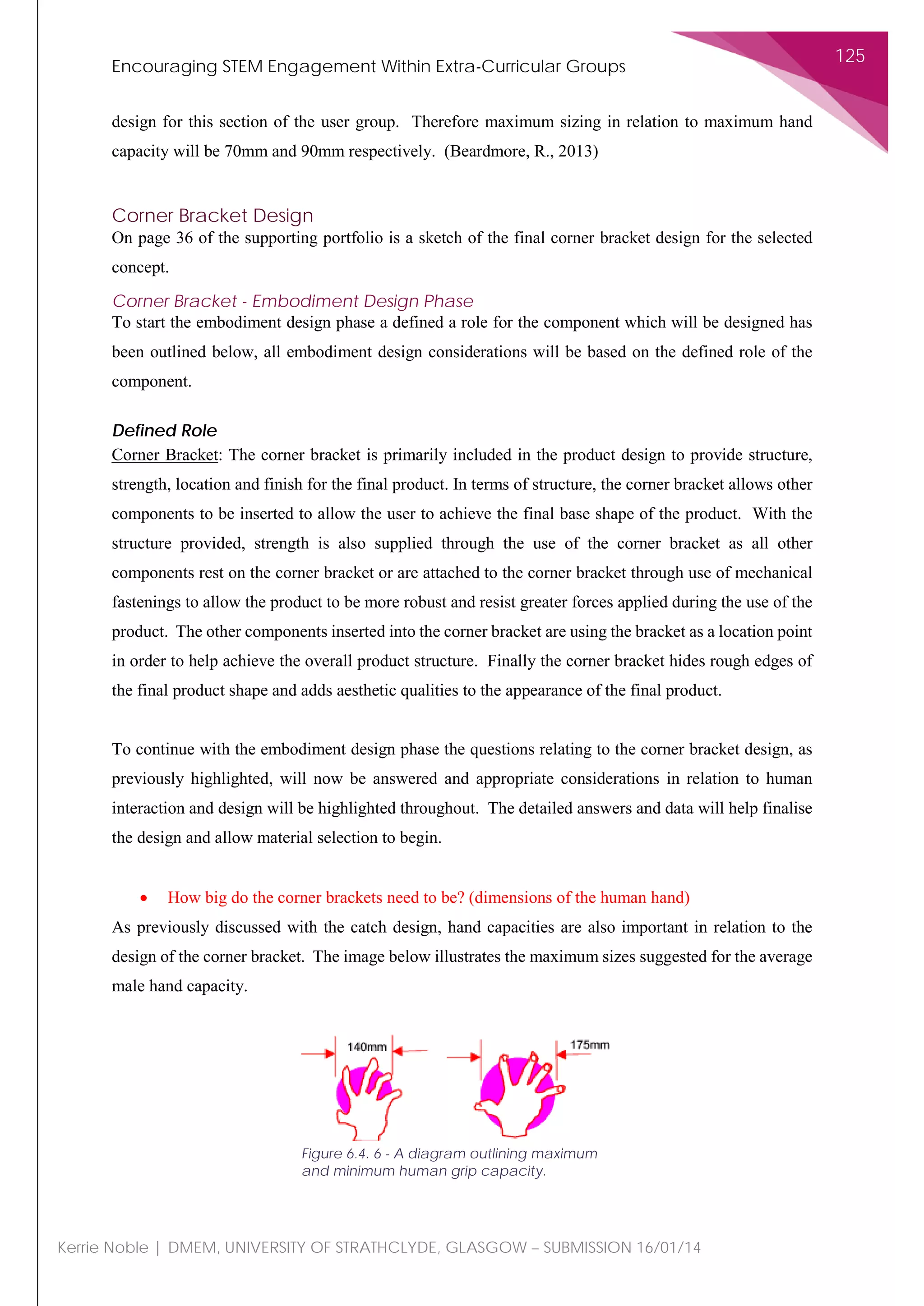
• Will the pressure asserted on the swivel mechanism have an adverse frictional effect on the
material? If so how much wear will this create on the material? [2]
While designing for strength conditions there are many considerations to design for and the most
appropriate considerations for this project are;
• Arm/Hand and Thumb-Finger strength – As addressed by the previous question, the force
exerted by the thumb and finger grip strength may have a significant impact on the swivel
mechanism design with regards to the material and the operational ability of the component.
• Static Push/Pull Force – As the user is required to push and pull the component to induce
rotation this force application also requires consideration. Again the 5th
percentile female static
push force and the 95th
percentile female static push force will be considered within this project
to demonstrate the extremities relating to the force applications associated with product
operation across the target user group.
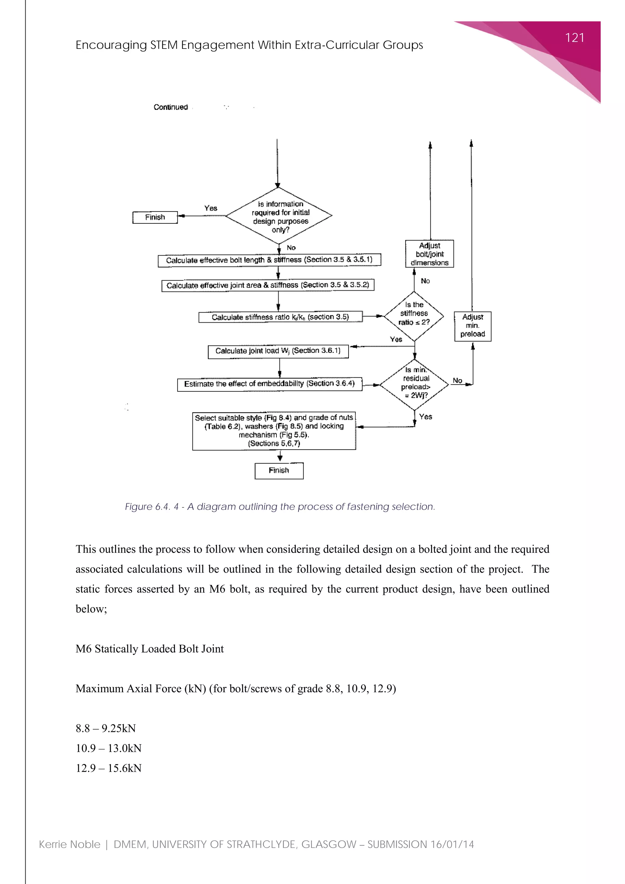
• Compression Force (Fastenings) – The swivel mechanism is a statically loaded bolted joint
when not under the influence of user applied forces. This means that the load bearing
mechanism component needs to have sufficient material strength to withstand the static load
bearing of an M6 bolt which is specified within the current design.
These points will be further considered below.
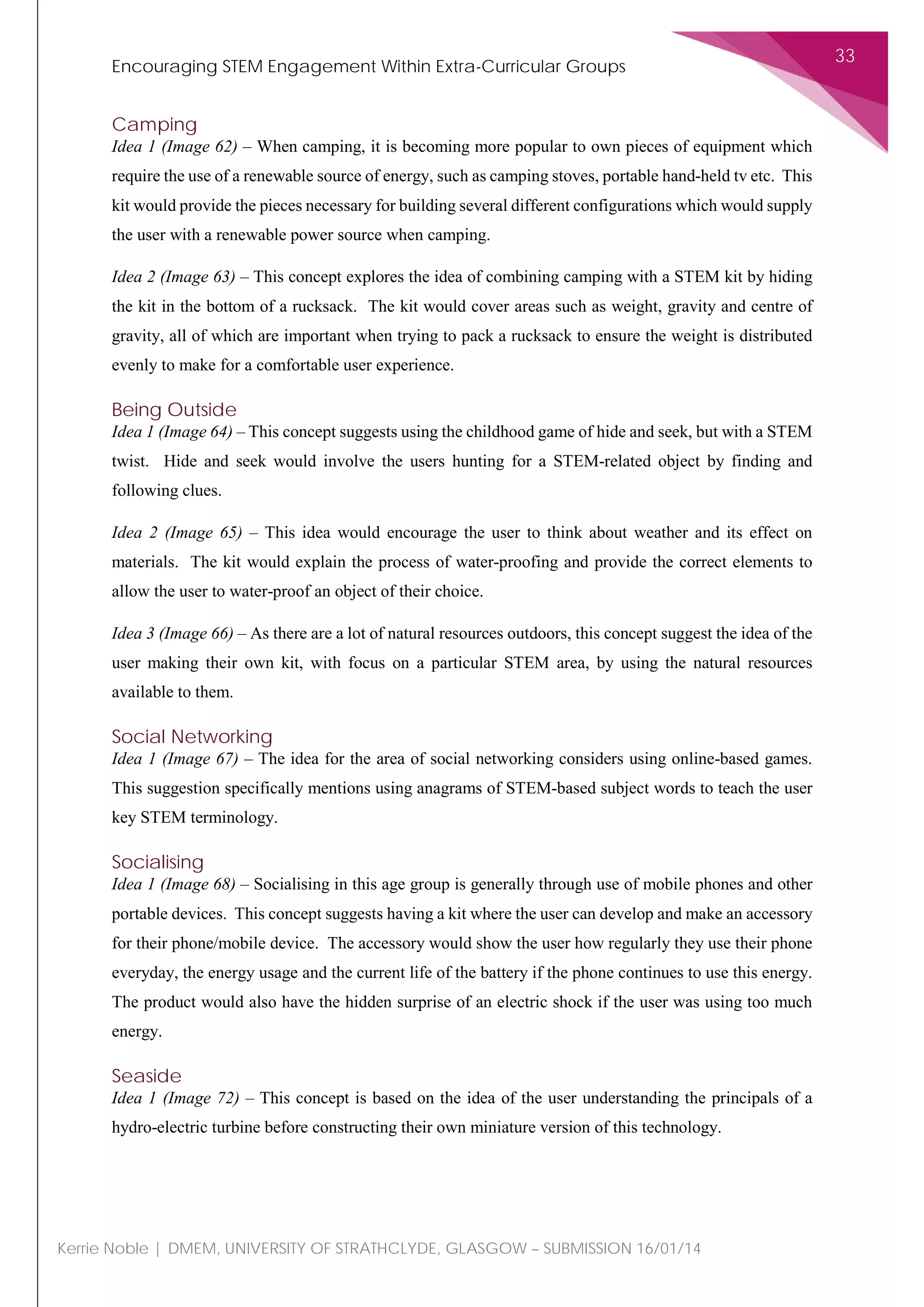
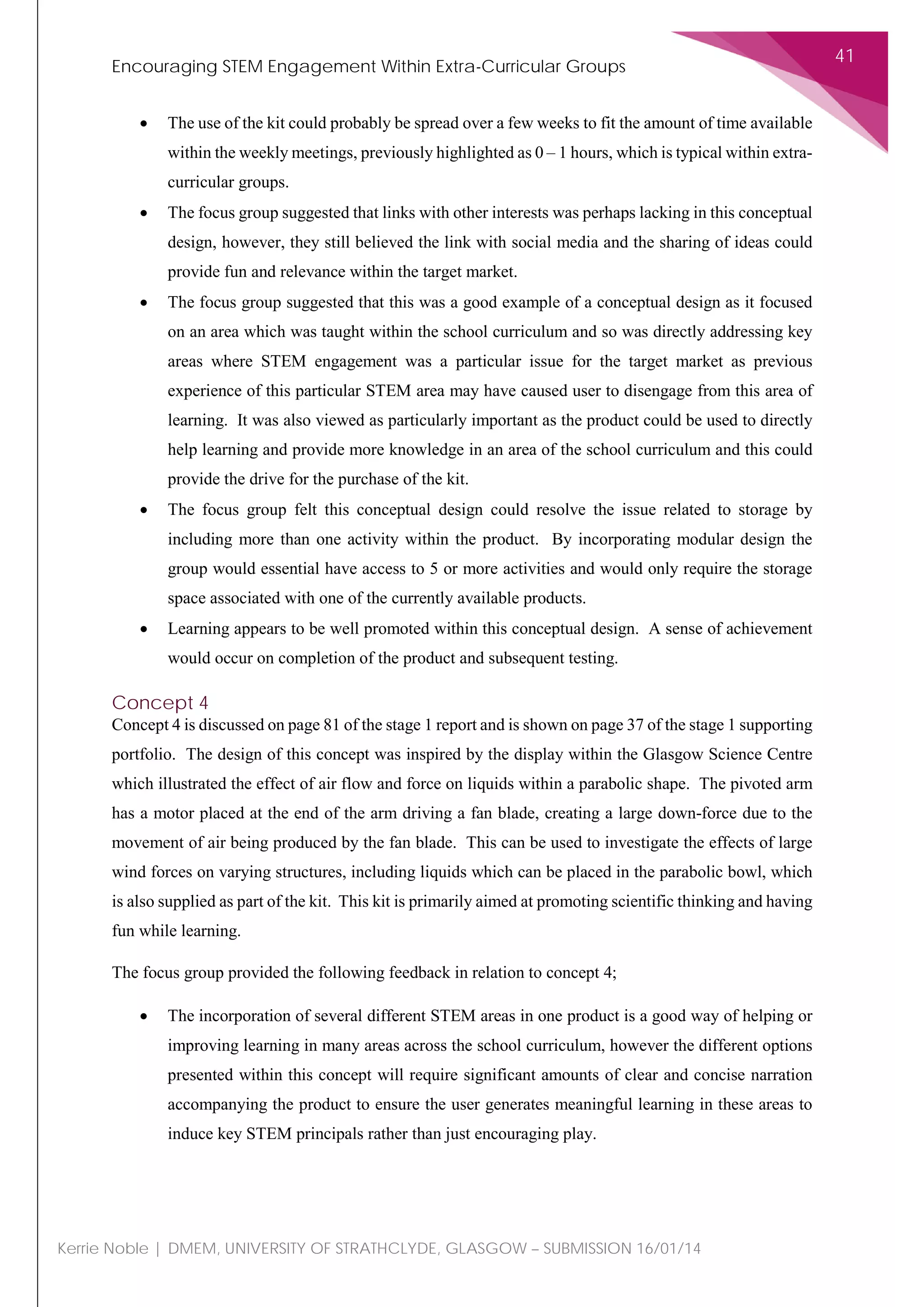
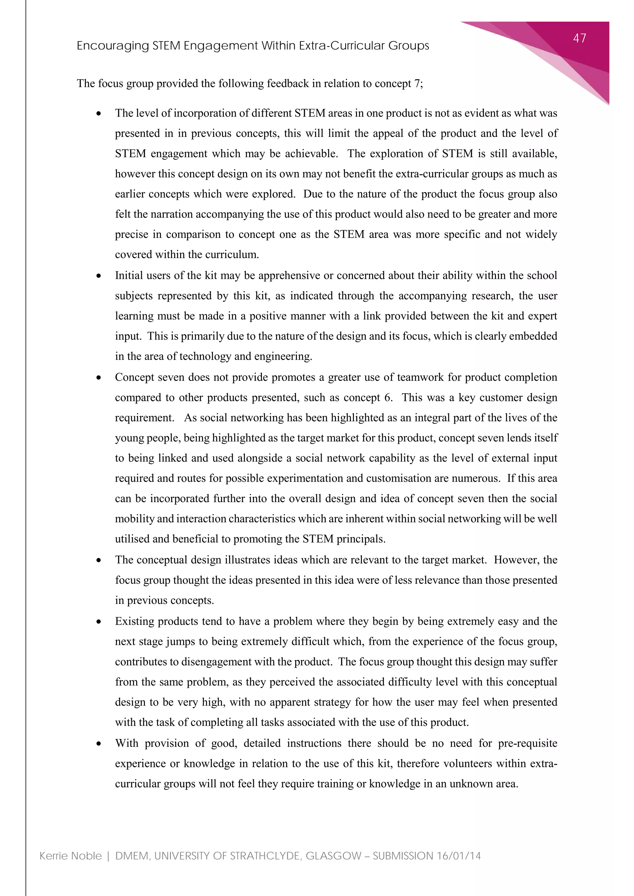
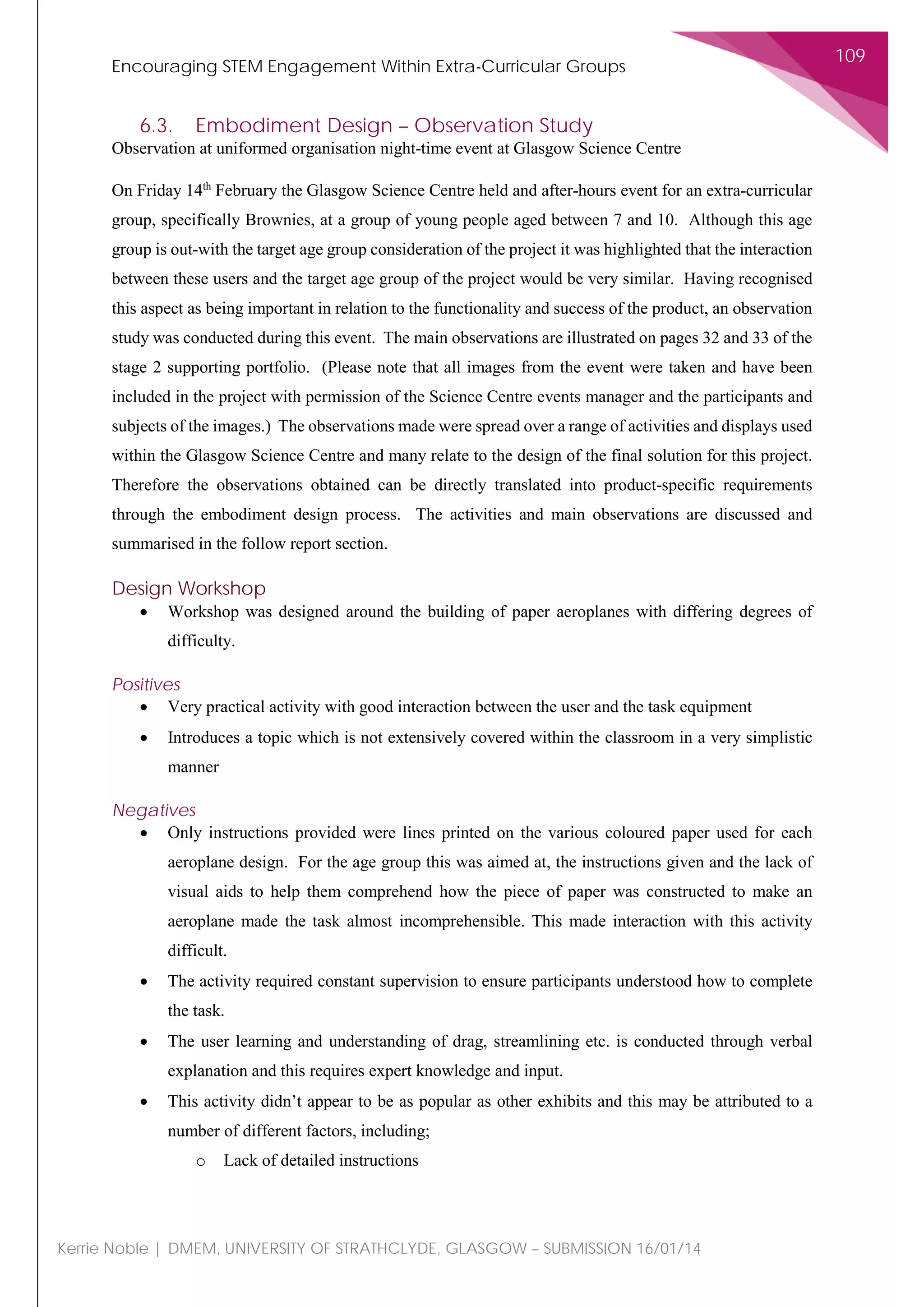
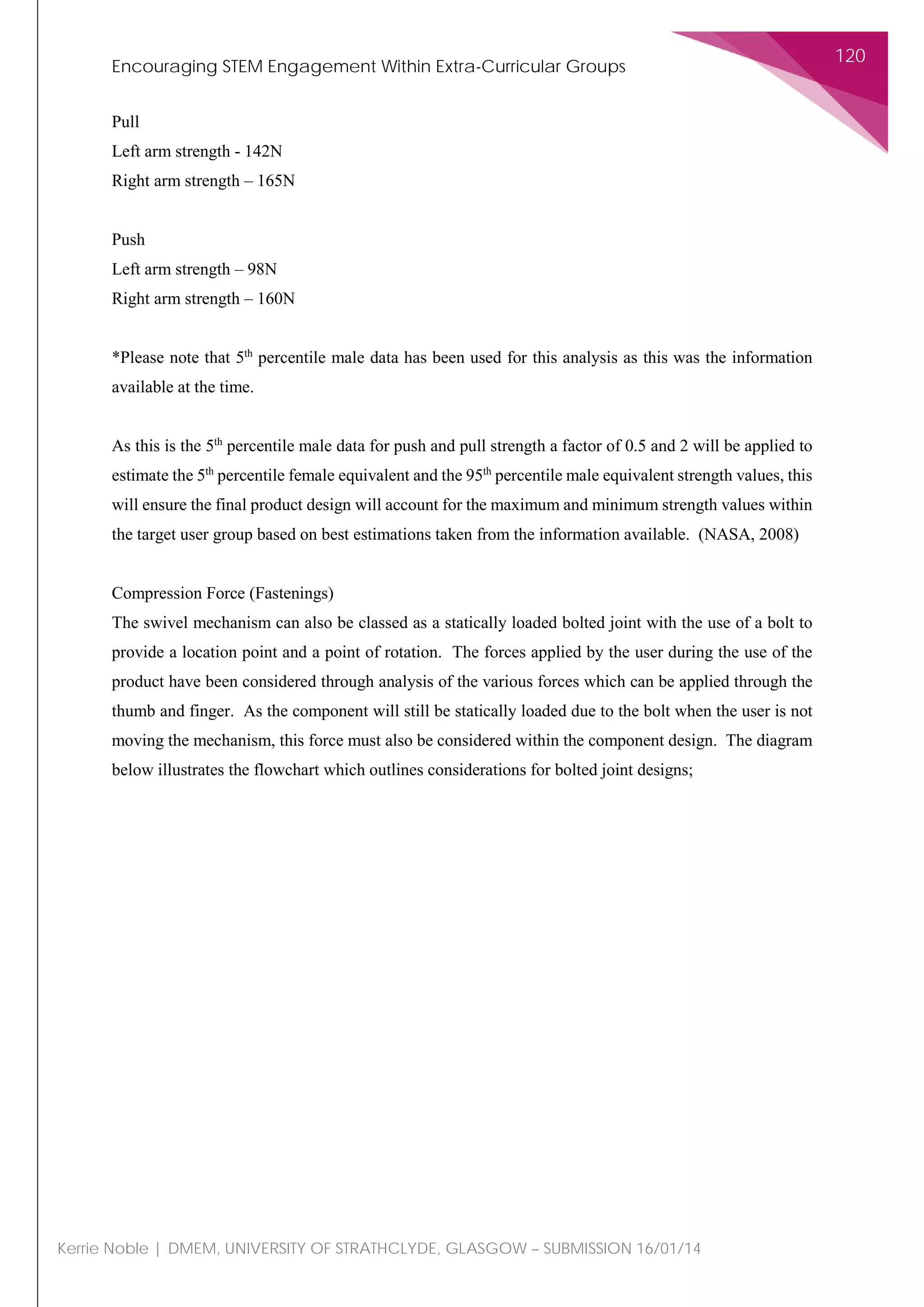
Static Push/Pull Strength
As with the section above where thumb and finger strength has been considered, the stated values within
the static push/pull strength analysis are also taken assuming that the product will be utilised within the
normal seated position, therefore meaning the users’ arm is bent at 90 degrees with the arm parallel to
the ground so elbow flexion is taken as Ω/2.
5th
percentile male push strength
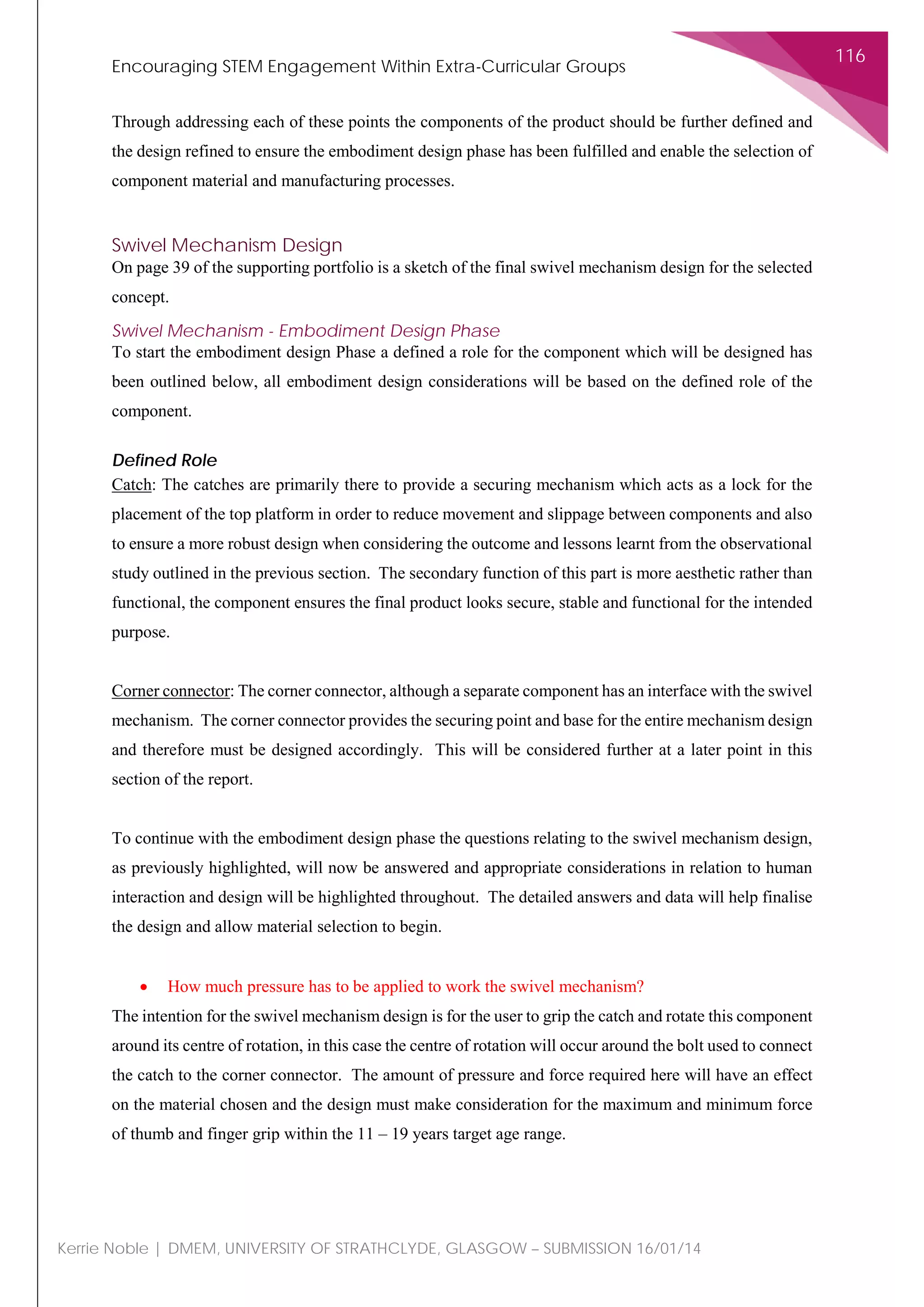
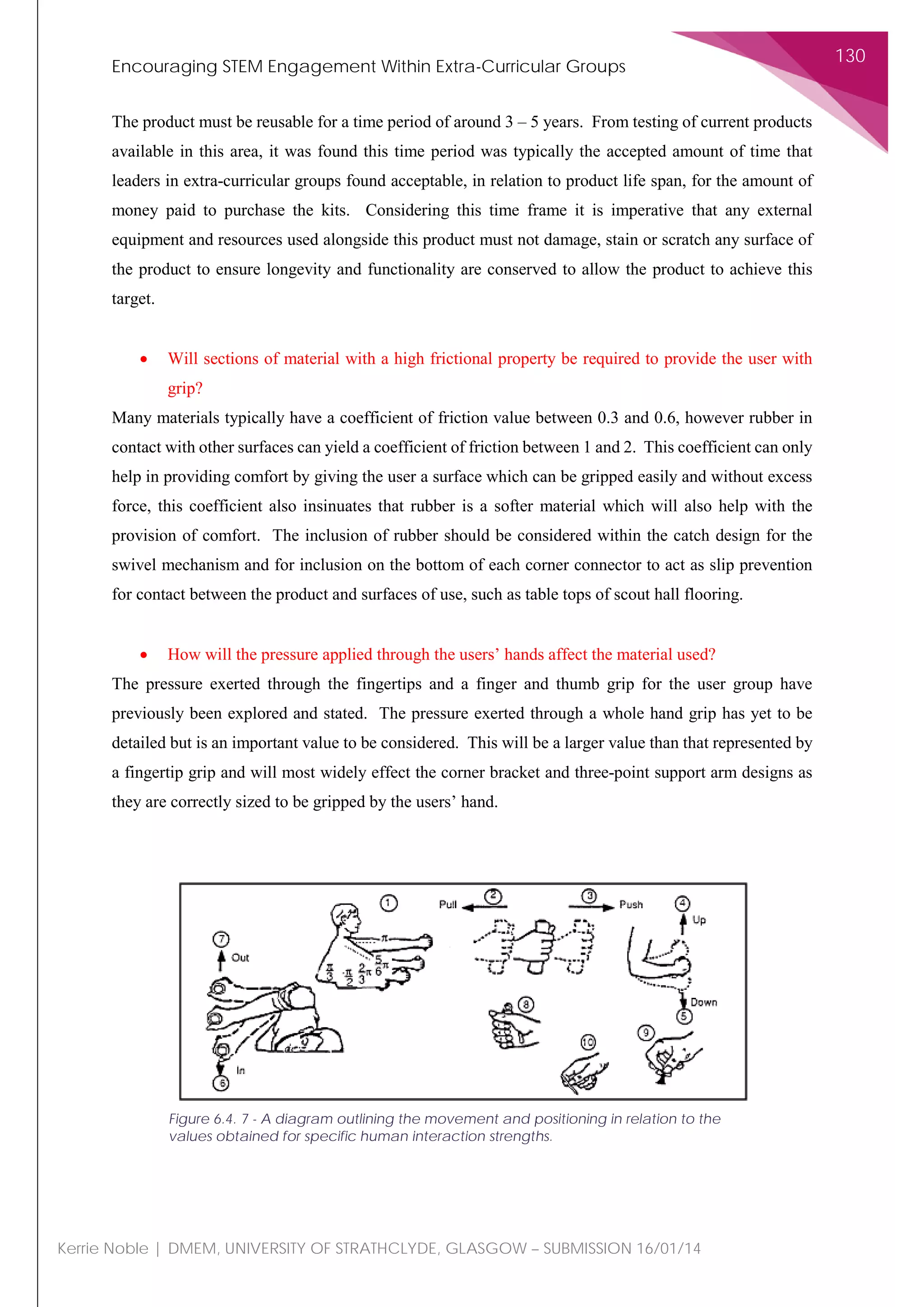
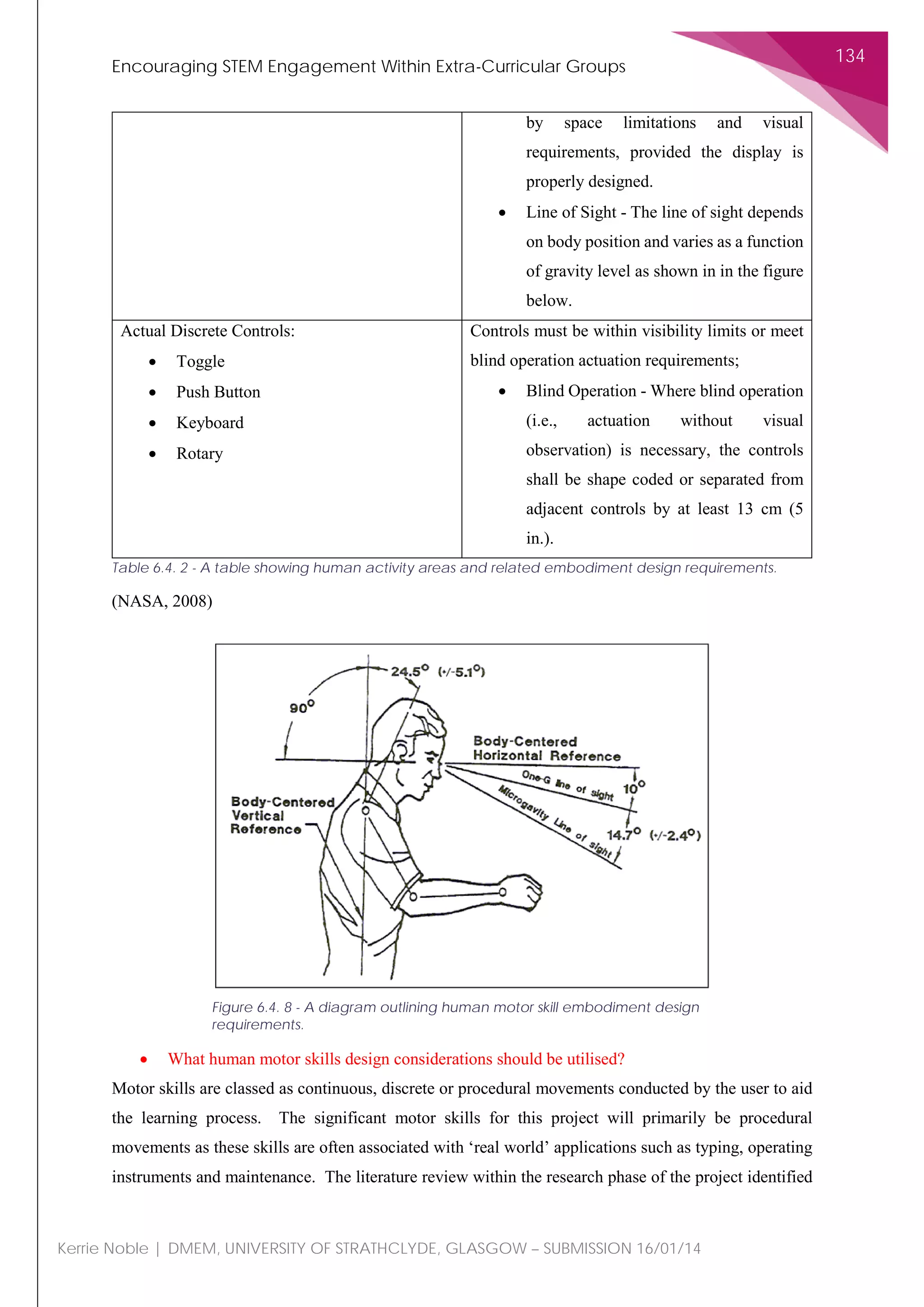
Figure 6.4. 3 - A diagram
outlining the push/pull strength
discussed within the
embodiment design.](https://image.slidesharecdn.com/b7190c6a-ea70-4ccb-a3d1-64d537c797e7-151124225215-lva1-app6892/75/Stage-2-Report-120-2048.jpg)


![Encouraging STEM Engagement Within Extra-Curricular Groups
209
Kerrie Noble | DMEM, UNIVERSITY OF STRATHCLYDE, GLASGOW – SUBMISSION 16/01/14
References
Adams, J.A. (1987). Historical review and appraisal of research on the learning, retention, and transfer
of human motor skills. Psychological Bulletin, 101, 41-74
APIS, 2011, Acid Deposition, [ONLINE] Available at;
http://www.apis.ac.uk/overview/pollutants/overview_Acid_deposition.htm, accessed 22/04/2014
Argotec, 2014, Glossary, [ONLINE] Available at; http://www.argotec.com/RF_Glossary.html,
accessed 22/04/2014
ASTM, 2014, Fire standards and flammability standards, [ONLINE] Available at;
http://www.astm.org/Standards/fire-and-flammability-standards.html , accessed 22/04/2014
BBC News, 2013 Scottish Scout Numbers on the Rise, Online, Available at www.bbc.co.uk/news/uk-
scotland-22230007, Accessed 17/10/13
BCS, 2013, Grand Theft Auto V, [ONLINE] Available at;
http://www.bcs.org/content/conWebDoc/51507 accessed 10 January 2014
Beardmore, R., 2013, Anthropometric Data, [ONLINE] Available at;
http://www.roymech.co.uk/Useful_Tables/Human/Human_sizes.html , accessed 22/04/2014
Beer, Ferdinand P.; E. Russel Johnston, Jr. (1996). Vector Mechanics for Engineers (Sixth ed.).
McGraw-Hill. p. 397. ISBN 0-07-297688-8.
Biggs, J., 1993, “What do inventories of students’ learning processes really measure? A theoretical
review and clarification,” British Journal of Educational Psychology, 63 (1): 3-19
Bolt Depot, 2014, About fastener materials, [ONLINE] Available at;
http://www.boltdepot.com/fastener-information/materials-and-grades/materials.aspx, accessed
22/04/2014
Boyce, G., Williams, S., Kelly, A., & Yee, H., 2001, “Fostering deep and elaborative learning and
generic (soft) skill development: Strategic use of case studies in accounting education,” Accounting
Education, 10 (1), 37-60
Carbon Trust, 2014, Carbon Footprinting Guide, [ONLINE] Available at;
http://www.carbontrust.com/resources/guides/carbon-footprinting-and-reporting/carbon-footprinting,
accessed 22/04/2014
Case Western Reserve University, 2014, Thermal properties of polymers, [ONLINE] Available at;
http://plc.cwru.edu/tutorial/enhanced/files/polymers/therm/therm.htm, accessed 22/04/2014
D4S, 2014, Design for Sustainability, [ONLINE] Available at; http://www.d4s-de.org/, accessed
22/04/2014](https://image.slidesharecdn.com/b7190c6a-ea70-4ccb-a3d1-64d537c797e7-151124225215-lva1-app6892/75/Stage-2-Report-210-2048.jpg)
![Encouraging STEM Engagement Within Extra-Curricular Groups
210
Kerrie Noble | DMEM, UNIVERSITY OF STRATHCLYDE, GLASGOW – SUBMISSION 16/01/14
Department for Business Innovation and Skills, 2012, Engaging the Public in Science and Engineering,
Online, Available at https://www.gov.uk/government/policies/engaging-the-public-in-science-and-
engineering--3/supporting-pages/inspiring-students-to-study-science-technology-engineering-and-
mathematics, Accessed 14/10/13
Department for Business, Innovation and Skills, 2012, Engaging the Public in Science and Engineering,
Online, Available at https://www.gov.uk/government/policies/engaging-the-public-in-science-and-
engineering--3, Accessed 14/10/13
Department for Education, 2008, After-school Science and Engineering Clubs Evaluation: Final Report,
London
Department for Education, 2010, The STEM Cohesion Programme: Final Report, London
Department of Further Education, Employment, Science and Technology (Australia), 2013, Female
Participation in STEM Study and Work in South Australia 2012, Adelaide
Dow Corning, 2012, Application centre glossary, [ONLINE] Available at;
http://www.google.co.uk/url?sa=t&rct=j&q=&esrc=s&source=web&cd=1&ved=0CC8QFjAA&url=h
ttp%3A%2F%2Fwww.dowcorning.com%2Fcontent%2Fpublishedlit%2F11-2092.pdf&ei=O2g8U-3-
B4LRhAe374CQCg&usg=AFQjCNEjhs0v5RvdqM4ArjwiJv0tqBMz-A&sig2=N92eRTSK2-
vcOXZfB7YNXQ , accessed 22/04/2014
Dowson, Duncan (1997). History of Tribology, 2nd Edition. Professional Engineering Publishing.
ISBN 1-86058-070-X.
England, G., 2011, Reducing Wear by Using Thermal Spray Coatings, [ONLINE] Available at;
http://www.gordonengland.co.uk/wear.htm#TSC1, accessed 22/04/2014
EU Commission, 2014, Energy and Environment, [ONLINE] Available at;
http://ec.europa.eu/environment/integration/energy/index_en.htm, accessed 22/04/2014
Eurostat (European Commission), 2011, Education Statistics, Brussels
Evidence for Policy and Practice Information and Co-ordinating Centre, 2010, Subject Choice in
STEM: Factors Influencing Young People (aged 14-19) in Education (A systematic review of the UK
literature), University of London
Experience UI, 2009, User Centred Design Definition, Online, Available at; experience.expressionz.in,
Accessed 14/10/13
Facebook, 2014, 1st
Facebook Scout Group, [ONLINE] Available at;
https://www.facebook.com/groups/2450689742/ accessed 9 January 2014](https://image.slidesharecdn.com/b7190c6a-ea70-4ccb-a3d1-64d537c797e7-151124225215-lva1-app6892/75/Stage-2-Report-211-2048.jpg)
![Encouraging STEM Engagement Within Extra-Curricular Groups
211
Kerrie Noble | DMEM, UNIVERSITY OF STRATHCLYDE, GLASGOW – SUBMISSION 16/01/14
Freudenrich, C., 2014, How rubber works, [ONLINE] Available at;
http://science.howstuffworks.com/rubber.htm/printable , accessed 22/04/2014
Girl Scouts of America Research Institute, 2012, Generation STEM: What Girls Say About Science,
Technology, Engineering and Maths, Lockheed Martin
GoldieBlox, 2013, GoldieBlox: Building games for girls to inspire future engineers, Online, Available
at www.goldieblox.com/pages/about, Accessed 18/10/13
Gustafsson, E., 2013, Investigation of friction between plastic parts, Master's thesis in Polymer
tribology, [ONLINE] Available at;
http://www.google.co.uk/url?sa=t&rct=j&q=&esrc=s&source=web&cd=4&ved=0CEwQFjAD&url=h
ttp%3A%2F%2Fpublications.lib.chalmers.se%2Frecords%2Ffulltext%2F181751%2F181751.pdf&ei
=2Jo5U762L4iA7Qa-
FQ&usg=AFQjCNGrWQ05wZjVPkXNFIaVSQ8dUn16mw&sig2=L7LRs9rRJfo557QlpKHwIg ,
accessed 22/04/2014
Hamaker, J., 2009, The Rise of Social Networking Sites and Their Effects on Our Lives, [ONLINE]
Available at; http://ezinearticles.com/?The-Rise-of-Social-Networking-Sites-and-Their-Effects-on-
Our-Lives&id=2887717 accessed 9 January 2014
Harrison, Medrington & Stransom, 2013, User Centred Design Research Methods for Mobile Industry
Practitioners, WI Journal of Mobile Media, Sound Moves, Vol.7 No.1, March 2013
IMBD, 2013, Most Popular Video Games Released in 2013, [ONLINE] Available at;
http://www.imdb.com/search/title?sort=moviemeter&title_type=game&year=2013,2013 accessed 9
January 2014
IPSOS MORI Social Research Institute, 2011, Public Attitudes to Science, Department for Business
Innovation and Skills, London
Johnson, T., 2014, Plastics in children’s toys, [ONLINE] Available at;
http://composite.about.com/od/Plastics/a/Plastics-In-Children-S-Toys.htm , accessed 22/04/2014
Kalpakjian & Schmid, 2009, Manufacturing Engineering and Technology, Sixth Edition, Prentice Hall,
Singapore
Keithley, 2001, Volume and Surface Resistivity Measurements of Insulating Materials Using the Model
6517A Electrometer/High Resistance Meter, [ONLINE] Available at;
http://www.google.co.uk/url?sa=t&rct=j&q=&esrc=s&source=web&cd=2&ved=0CDYQFjAB&url=
http%3A%2F%2Fwww.keithley.co.uk%2Fdata%3Fasset%3D6069&ei=SmY8U8qTDMqshQeQyYG
gCw&usg=AFQjCNGjYOiwffUs37foyRMum9HolCE9Vg&sig2=7nBjMy2n0EXk12z541i7iw ,
accessed 22/04/2014](https://image.slidesharecdn.com/b7190c6a-ea70-4ccb-a3d1-64d537c797e7-151124225215-lva1-app6892/75/Stage-2-Report-212-2048.jpg)
![Encouraging STEM Engagement Within Extra-Curricular Groups
212
Kerrie Noble | DMEM, UNIVERSITY OF STRATHCLYDE, GLASGOW – SUBMISSION 16/01/14
Kent, R., 2009, What’s your process energy fingerprint?, [ONLINE] Available at;
http://www.ptonline.com/articles/whats-your-process-energy-fingerprint, accessed 22/04/2014
K’NEX, 2013, Online, Available at www.knex.com/products, Accessed 17/10/13
Knowledge Project, 2013, Eutrophication: Causes, Consequences and Controls in Aquatic Ecosystems,
[ONLINE] Available at; http://www.nature.com/scitable/knowledge/library/eutrophication-causes-
consequences-and-controls-in-aquatic-102364466, accessed 22/04/2014
Lego Mindstorm picture http://education.lego.com/en-gb/lego-education-product-
database/mindstorms/9797-lego-mindstorms-education-base-set
Lego education2, 2013, http://shop.legoeducation.com/gb/product/lego-mindstorms-education-nxt-
base-set-9797-29/
Lord Sainsubury, 2007, The Race to The Top: A Review of Government’s Science and Innovation
Policies, October 2007
Lyondell, 2014, Mould shrinkage, [ONLINE] Available at;
http://www.google.co.uk/url?sa=t&rct=j&q=&esrc=s&source=web&cd=2&ved=0CDgQFjAB&url=h
ttp%3A%2F%2Fwww.lyondellbasell.com%2Ftechlit%2Ftechlit%2FTech%2520Topics%2FGeneral%
2FMold%2520Shrinkage.pdf&ei=fGI8U7zRApOShQflsoHADw&usg=AFQjCNGta2DvS0-
Sh_rAIXBeyYw5BVPBmg&sig2=6WFmJs5-mll4o5fFKcX5TQ&bvm=bv.63934634,d.ZWU ,
accessed 22/04/2014
Lyondell Chemical Company, 2014, A guide to polyolefin sheet extrusion, [ONLINE] Available at;
http://www.lyondellbasell.com/techlit/techlit/Brochures/Sheet%20Extrusion%209531.pdf, accessed
22/04/2014
Mashable, 2013, Social Networking, [ONLINE] Available at; http://mashable.com/category/social-
networking/ accessed 9 January 2014 (and social networking image)
Marteniuk, R. (1976). Information Processing in Motor Skills. New York: Holt, Rinehart & Winston.
Marton, F., & Säljö, R., 1976a, “Qualitative differences in learning I. Outcomes and processes,” British
Journal of Educational Psychology, 46, 4-11
Marton, F., & Säljö, R., 1976b, “On qualitative differences in learning II. Outcomes as a function of the
learners’ conception of the task,” British Journal of Educational Psychology, 46, 115-127
Mat Web, 2014, Material property search, [ONLINE] Available at;
http://www.matweb.com/search/search.aspx , accessed 22/04/2014
Mayer, R.E., & Chandler, P., 2001, “When learning is just a click away: Does simple user interaction
foster deep understanding of multimedia messages?”, Journal of Educational Psychology, Vol. 93, No.
2, 390-397, American Psychological Association INC.](https://image.slidesharecdn.com/b7190c6a-ea70-4ccb-a3d1-64d537c797e7-151124225215-lva1-app6892/75/Stage-2-Report-213-2048.jpg)
![Encouraging STEM Engagement Within Extra-Curricular Groups
213
Kerrie Noble | DMEM, UNIVERSITY OF STRATHCLYDE, GLASGOW – SUBMISSION 16/01/14
Mayer, R.E., & Moreno, R., 2003, “Nine ways to reduce cognitive load in multimedia learning,”
Educational Psychologist, 38 (1) 43-52, Lawrence Erlbaum Associates, INC.
Merriam-Webster, 2014, Back-pressure, [ONLINE] Available at; http://www.merriam-
webster.com/dictionary/back%20pressure, accessed 22/04/2014
Met Office, 2014, Monthly temperature records by country, [ONLINE] Available at;
http://www.metoffice.gov.uk/climate/uk/extremes/monthly_temperature_country.html#highest_daily_
maximum_england , accessed 22/04/2014
Micro Chem, 2014,Material properties definitions, [ONLINE] Available at;
http://www.microchem.com/Tech-MaterialPropDefs.htm , accessed 22/04/2014
Mirror, 2013, 2011 Census: The main 20 languages spoken in the UK, available at
http://www.mirror.co.uk/news/uk-news/2011-census-top-20-languages-1563629, accessed 30
September 2013
Mischel, W., 2013, “Personality and Assessment,” Psychology Press, Taylor and Francis Group, 15
April 2013, Hove, United Kingdom
National Academy of Engineering, 2013, Engineer Girl: Debbie Sterling, Online, Available at
www.engineergirl.org/Engineers/Directory/13512.aspx, Accessed 18/10/13
NASA, 2008, Volume I, Section 4: 4 HUMAN PERFORMANCE CAPABILITIES, [ONLINE]
Available at; http://msis.jsc.nasa.gov/sections/section04.htm , accessed 22/04/2014
NIST, 2006, Specular Gloss, [ONLINE] Available ay;
http://www.google.co.uk/url?sa=t&rct=j&q=&esrc=s&source=web&cd=7&ved=0CF0QFjAG&url=ht
tp%3A%2F%2Fwww.nist.gov%2Fcalibrations%2Fupload%2Fsp250-70.pdf&ei=6mg8U-
meDYKrhQff3IHwCA&usg=AFQjCNFI7jdI51nrC6oqD_mrzJTdwKpRlA&sig2=tYlVVbjhSoXLzQ-
fqymYGQ , accessed 22/04/2014
Office for National Statistics, Historic UK Population Pyramid, Census Figures 2011, Online, Available
at www.ons.gov.uk/ons/interactive/historic-uk-population-pyramid/index.html, Accessed 14/10/13
Persson, B. N.; Volokitin, A. I (2002). "Theory of rubber friction: Nonstationary sliding". Physical
Review B 65 (13): 134106. Bibcode:2002PhRvB..65m4106P. doi:10.1103/PhysRevB.65.13410
Pintirch, P.R., 2002, “The role of metacognitive knowledge in learning, teaching and assessing,” Theory
into Practice, Vol. 41, No. 4, Revising Bloom’s Taxonomy, 219-225
Polymer Engineering Guide, 2012, Elastomer engineering guide, [ONLINE] Available at;
http://www.google.co.uk/url?sa=t&rct=j&q=&esrc=s&source=web&cd=6&ved=0CFkQFjAF&url=ht
tp%3A%2F%2Fwww.jameswalker.biz%2Fen%2Fpdf_docs%2F148-elastomer-engineering-
guide&ei=OmM8U72JM8-](https://image.slidesharecdn.com/b7190c6a-ea70-4ccb-a3d1-64d537c797e7-151124225215-lva1-app6892/75/Stage-2-Report-214-2048.jpg)
![Encouraging STEM Engagement Within Extra-Curricular Groups
214
Kerrie Noble | DMEM, UNIVERSITY OF STRATHCLYDE, GLASGOW – SUBMISSION 16/01/14
AhAegk4CABw&usg=AFQjCNH7wIHA9RDs8IUjylQbpICq84QOgA&sig2=TnZv3fl1OWzLuqh7w
zYAXQ , accessed 22/04/2014
TEDxTalks, 2013, Inspiring the next generation of female engineers: Debbie Sterling at TEDxPSU,
Online, Available at www.youtube.com/watch?v=FEeTLopLkEo, Accessed 19/10/13
The design society, 2011, Design Procedures for Statically Loaded Bolted Joints, [ONLINE] Available
at; http://www.bath.ac.uk/idmrc/themes/projects/delores/co-design-website/dpg/bol/bol3.html ,
accessed 22/04/2014
Resin Supplies, 2014, Casting Resins, [ONLINE] Available at; http://www.resin-
supplies.co.uk/casting%20resin%20detailed.htm , accessed 22/04/2014
The Royal Academy of Engineering, 2007, Educating Engineers for the 21st Century, London
The Russell Group of Universities, (February 2009), STEM-Briefing, London
Sandoval, W. A., 2004, “Understanding student’s practical epistemologies and their influence on
learning through inquiry,” Sci Ed, 89: 634-656, Wiley Periodicals INC.
Scott, R., 2008, Basic Wear Modes in Lubricated Systems, [ONLINE] Available at;
http://www.machinerylubrication.com/Read/1375/wear-modes-lubricated , accessed 22/04/2014
Singer, R.N. (1975). Motor Learning and Human Performance (2nd Ed.). New York: Macmillan
Skinner, B. F., 2012, “I The Science of Learning and the Art of Teaching,” Readings in Educational
Psychology, Learning and Teaching, E. Stones, Routledge Library Editions: Education, 4th
May 2012,
pp. 301-309
Startasys, 2014, Finishing Touch Smoothing Station: Expanding Possibilities, [ONLINE] Available at;
http://www.stratasys.com/applications/finishing/smoothing-fdm-parts , accessed 22/04/2014
Stevens, H., 2012, Employer Engagement in STEM Learning in the Heart of the South West, University
of Exeter
Sweller, 1999, “Instructional Design in Technical Areas,” Camberwell, Australia, Acer Press
Thomasnet, 2014, What is laser cutting?, [ONLINE] Available at;
http://www.thomasnet.com/articles/custom-manufacturing-fabricating/laser-cutting-technology,
accessed 22/04/2014
Tian, Y., & Gao, F., 1999, Ind. Eng. Chem. Res., 1999, 38 (9), pp 3396–3406, DOI: 10.1021/ie980535p
Publication Date (Web): August 14, 1999 Copyright © 1999 American Chemical Society
Translators Café, 2014, Electrical Resistivity, [ONLINE] Available at;
http://www.translatorscafe.com/cafe/EN/units-converter/electric-resistivity/d/ , accessed 22/04/2014
UL, 2014, UL 94, the Standard for Safety of Flammability of Plastic Materials for Parts in Devices and
Appliances testing, [ONLINE] Available at;](https://image.slidesharecdn.com/b7190c6a-ea70-4ccb-a3d1-64d537c797e7-151124225215-lva1-app6892/75/Stage-2-Report-215-2048.jpg)
![Encouraging STEM Engagement Within Extra-Curricular Groups
215
Kerrie Noble | DMEM, UNIVERSITY OF STRATHCLYDE, GLASGOW – SUBMISSION 16/01/14
http://www.ul.com/global/eng/pages/offerings/industries/chemicals/plastics/testing/flame/ , accessed
22/04/2014
Understanding energy consumption in injection moulding machine, [ONLINE] Available at;
http://www.pitfallsinmolding.com/energyeffic1.html, accessed 22/04/2014
Wiki Answers, 2014, How many miles from England to China?, [ONLINE] Available at;
http://wiki.answers.com/Q/How_many_miles_from_England_to_China#slide=3&article=How_many
_miles_from_England_to_China, accessed 22/04/2014
Williamson Corporation, 2014, Die Temperature, [ONLNE] Available at;
http://www.williamsonir.com/die-temperature, accessed 22/04/2014
Yahoo Answers, 2011, What materials are used for children’s toys?, [ONLINE] Available at;
https://uk.answers.yahoo.com/question/index?qid=20110418143658AAZvzSy , accessed 22/04/2014](https://image.slidesharecdn.com/b7190c6a-ea70-4ccb-a3d1-64d537c797e7-151124225215-lva1-app6892/75/Stage-2-Report-216-2048.jpg)