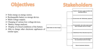
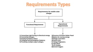
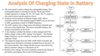
Topic: Solar Based Mobile Charger
 Purpose:
Mobile phone plays an important role in communication. The growth of mobile phone market is phenomenal in recent
years and the need for charging the mobile battery is required anytime and anywhere. It becomes very difficult to
charge the mobile phone while travelling from one place to another and when current supply is not available while in
the home, office etc.
 Scope:
In today’s environment conscious world, a lot of interest is being taken in alternate forms of energy. Solar power is a
renewable source of energy, which has become increasingly popular in modern days. Today 80% of the energy we use
comes from fossil fuels and about 1% comes from solar energy. It is estimated that the world’s oil reserves will last for
30 to 40 years, whereas solar energy is forever. Solar energy has two big advantages over fossil fuels. The first is in the
fact that it is renewable; it is never going to run out. The second is its effect on the environment.
 Solar energy as energy source.
 Rechargeable battery as storage device.
 Multi-voltage outputs.
 Charging of various low-voltage devices.
 Battery charge analyser.
 Display of critical conditions of the battery
 Able to charge other electronic appliances of
similar types.
 The solar panel is used to charge the rechargeable battery. This
rechargeable battery is interfaced with the 78L05 and 78L09
voltage regulators to charge 5V, 9V, 12V loads. The 5V output is
also used to power-up the analyzer circuit.
 Analyzer circuit consists of Schmitt trigger, ADC, Micro-
controller and LCD. The Schmitt trigger CD4093 acts as the timer
to ADC, generating a clock of 550kHz frequency.
 The ADC analyzes the voltage across the battery terminals and
converts it into digital form. The micro-controller displays the
charge in the battery on the LCD.
 It also displays whether the battery is fully charged and if the
battery charge is below 20%, stating “low battery”. The Schmitt
trigger frequency can be varied by varying the external resistor,
capacitor values.
 The digitized output from the ADC (AD0-AD7) 4 transfers the
voltage across the battery terminals in digital form to the port 1 of
the microcontroller. The voltage-divider circuit scales-down the
battery terminal voltage to a maximum of 5V.
 Based on this voltage, the micro-controller analyzes the charge in
the battery and displays this on the LCD through port 2.
Time required for charging battery Voltage Recorded at particular time.

Solar based mobile charger

  • 1.
    Topic: Solar BasedMobile Charger
  • 2.
     Purpose: Mobile phoneplays an important role in communication. The growth of mobile phone market is phenomenal in recent years and the need for charging the mobile battery is required anytime and anywhere. It becomes very difficult to charge the mobile phone while travelling from one place to another and when current supply is not available while in the home, office etc.  Scope: In today’s environment conscious world, a lot of interest is being taken in alternate forms of energy. Solar power is a renewable source of energy, which has become increasingly popular in modern days. Today 80% of the energy we use comes from fossil fuels and about 1% comes from solar energy. It is estimated that the world’s oil reserves will last for 30 to 40 years, whereas solar energy is forever. Solar energy has two big advantages over fossil fuels. The first is in the fact that it is renewable; it is never going to run out. The second is its effect on the environment.
  • 3.
     Solar energyas energy source.  Rechargeable battery as storage device.  Multi-voltage outputs.  Charging of various low-voltage devices.  Battery charge analyser.  Display of critical conditions of the battery  Able to charge other electronic appliances of similar types.
  • 6.
     The solarpanel is used to charge the rechargeable battery. This rechargeable battery is interfaced with the 78L05 and 78L09 voltage regulators to charge 5V, 9V, 12V loads. The 5V output is also used to power-up the analyzer circuit.  Analyzer circuit consists of Schmitt trigger, ADC, Micro- controller and LCD. The Schmitt trigger CD4093 acts as the timer to ADC, generating a clock of 550kHz frequency.  The ADC analyzes the voltage across the battery terminals and converts it into digital form. The micro-controller displays the charge in the battery on the LCD.  It also displays whether the battery is fully charged and if the battery charge is below 20%, stating “low battery”. The Schmitt trigger frequency can be varied by varying the external resistor, capacitor values.  The digitized output from the ADC (AD0-AD7) 4 transfers the voltage across the battery terminals in digital form to the port 1 of the microcontroller. The voltage-divider circuit scales-down the battery terminal voltage to a maximum of 5V.  Based on this voltage, the micro-controller analyzes the charge in the battery and displays this on the LCD through port 2.
  • 7.
    Time required forcharging battery Voltage Recorded at particular time.