Downloaded 58 times


![Software Engineering Ontology
Design and Implementation
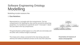
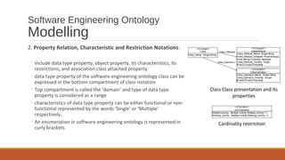
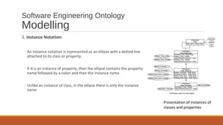
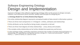
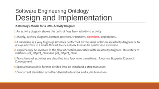
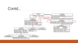
3. Ontology model for UML class diagram
1.A class diagram is a diagram that represents a set of classes and their interrelationships
2.There can be relationships among classes like generalisations, aggregations, and associations
3.The generalisation symbol appears as a line with one end empty and the other with a hollow triangle
arrowhead.
4.In the bottom compartment, notation are in the order of data type property name, its
characteristic ,its type and its restriction .The characteristics of data type property can be either
functional or nonfunctional represented by the words ‘Single’ or ‘Multiple’ respectively
5.An enumeration in software engineering ontology is represented in curly brackets
6. An object property can be expressed as an arrow with an open arrowhead and with a text label of
the object property’s name. Symbols , , and [] represent restrictions allValueFrom,∀ ∃
someValueFrom, and hasValue respectively](https://image.slidesharecdn.com/lo1flszt9i4gbyqem0gz-signature-8a48f36591ac252ea75208a3d9a5fb2a9736a7f6180bc595b6df63b778499348-poli-160127183827/85/Software-Engineering-Ontology-19-320.jpg)


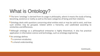
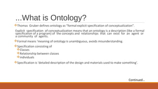
Ontology is a formal explicit specification of a conceptualization that provides a shared understanding of a domain. An ontology for software engineering can help facilitate communication between distributed development teams by providing a common vocabulary and conceptualization of key software engineering concepts and their relationships. Such an ontology can be modeled using notations like UML class diagrams and activity diagrams to represent important software engineering concepts like classes, activities, and relationships. The software engineering ontology then allows for improved knowledge sharing and communication framework among distributed development teams.