Download to read offline

![Software Engineering 14
SE Notes VIVEK SINHA, Asst. Proff. (CSE) SRIT
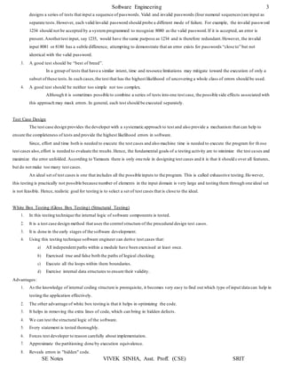
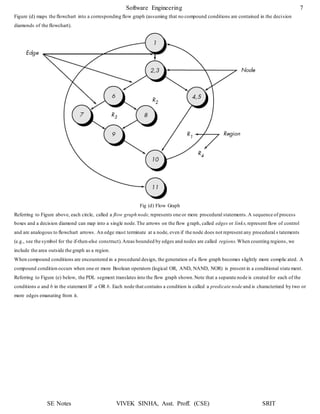
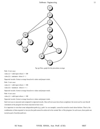
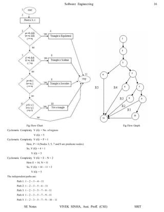
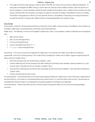
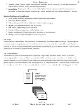
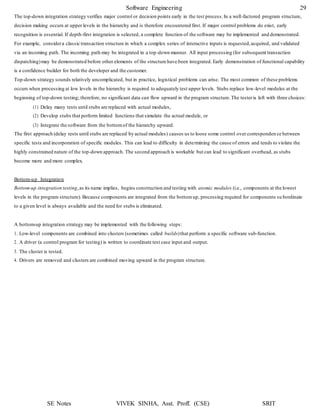
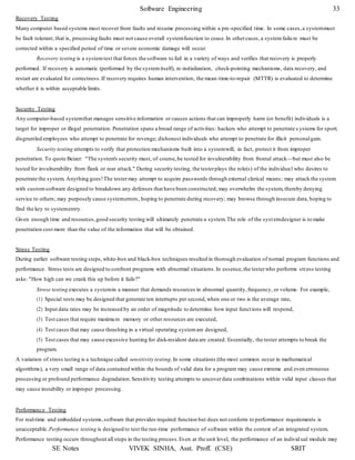
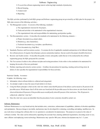
(c) Cyclomatic Complexity V (G) = No of regions
So, V (G) = 4
(d) Independent Paths:
Path 1: 1 – 2 – 3 – 7 – 8 – 12 – 11
Path 2: 1 – 2 – 4 – 5 – 9 – 10 – 11
Path 3: 1 – 2 – 4 – 5 – 6 – 10 – 11
Path 4: 1 – 2 – 4 – 5 – 10 – 11
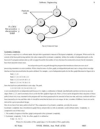
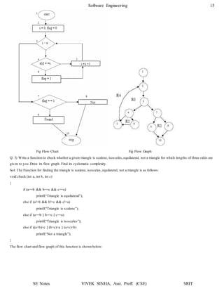
Q. 2) Determine the cyclomatic complexity for the function search.
void search (int a[ ], int n, int x)
{
int i = 0, flag = 0;
while (i<n)
{
if (a[i] == x)
{
}
i = i +1;
}
flag = 1;
break;
if (flag == 1)
printf(“found”);
else
}
printf(“Not”);
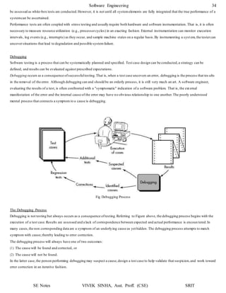
Sol:
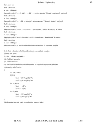
The flow chart & flow graph of function search is shown below:
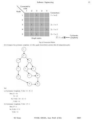
Cyclomatic Complexity V (G) = No. of Regions
V (G) = 4
Cyclomatic Complexity V (G) = E – N + 2
Here, E = 12
N = 10
So, V (G) = 12 – 10 + 2
V (G) = 4
Cyclomatic Complexity V (G) = P + 1
Here, P = 3 (Nodes 3, 4 and 7 are predicate nodes)
So, V (G) = 3 + 1
V (G) = 4](https://image.slidesharecdn.com/softwareenggunit4-200318102352/85/Software-engg-unit-4-14-320.jpg)
![Software Engineering 20
SE Notes VIVEK SINHA, Asst. Proff. (CSE) SRIT
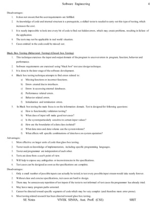
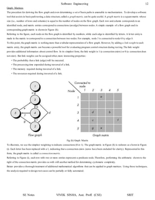
2. To illustrate the data flow testing approach, assume that each statement in a program is assigned a unique statement number a nd
that each function does not modify its parameters or global variables. For a statement with S as its statement number,
DEF(S) = {X | statement S contains a definition of X}
USE(S) = {X | statement S contains a use of X}
If statement S is an if or loop statement,its DEF set is empty and its USE set is based on the condition of statement S. The
definition of variable X at statement S is said to be live at statement S' if there exists a path from statement S to statement S' that
contains no other definition of X.
3. A definition-use (DU) chain of variable X is of the form [X, S, S'], where S and S' are statement numbers , X is in DEF(S) and
USE(S'), and the definition of X in statement S is live at statement S'.
4. One simple data flow testing strategy is to require that every DU chain be covered at least once. We refer to this strategy as the
DU testing strategy.
5. It has been shown that DU testing does not guarantee the coverage of all branches of a program. However, a branch is not
guaranteed to be covered by DU testing only in rare situations such as if-then-else constructs in which the then part has no
definition of any variable and the else part does not exist. In this situation, the else branch of the if statement is not necessarily
covered by DU testing.
6. Data flow testing strategies are usefulfor selecting test paths of a program containing nested if and loop statements.
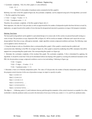
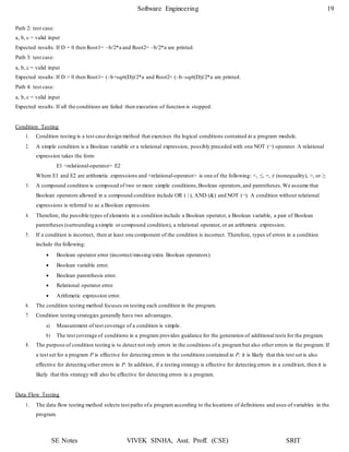
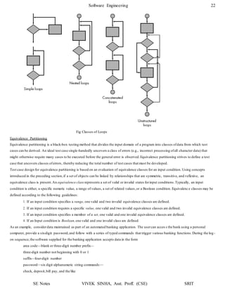
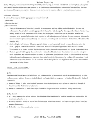
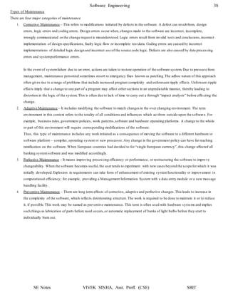
7. To illustrate this, consider the application of DU testing to select test paths for the PDL that follows:
proc x
B1;
do while C1
if C2
enddo;
B6;
end proc;
then
else
endif;
if C4
endif;
if C3
endif;
then B4;
else B5;
then B2;
else B3;
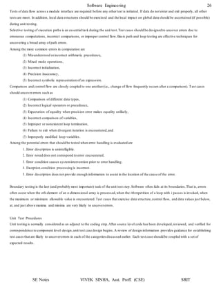
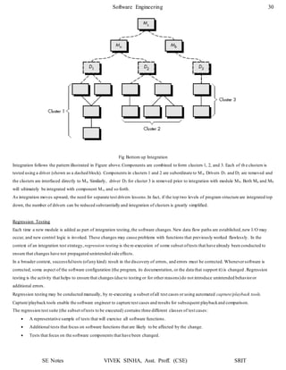
8. To apply the DU testing strategy to select test paths of the control flow diagram, we need to know the definitions and uses o f
variables in each condition or block in the PDL. Assume that variable X is defined in the last statement of blocks B1, B2, B3, B4,
and B5 and is used in the first statement of blocks B2, B3, B4, B5, and B6. The DU testing strategy requires an execution of the
shortest path from each of Bi, 0 < i ≤ 5, to each of Bj, 1 < j ≤ 6. (Such testing also covers any use of variable X in condit ions C1,
C2, C3, and C4.) Although there are 25 DU chains of variable X, we need only five paths to cover these DU chains. The reason is
that five paths are needed to cover the DU chain of X from Bi, 0 < i ≤ 5, to B6 and other DU chains can be covered by making
these five paths contain iterations of the loop.](https://image.slidesharecdn.com/softwareenggunit4-200318102352/85/Software-engg-unit-4-20-320.jpg)

1. The document discusses software testing and provides definitions, objectives, and types of testing. It defines testing as analyzing software to detect bugs and differences from requirements. 2. The primary objectives of testing are to design tests that systematically uncover errors with minimal time and effort. Exhaustive testing all possible inputs is not possible due to the large number of combinations. 3. White box testing uses the internal logic and structure of code to design test cases that execute all independent paths, loops, and internal data structures to ensure validity. It helps optimize code but does not ensure requirements are fulfilled and requires a skilled tester.