Download to read offline
![SE Notes VIVEK SINHA, Asst. Proff.(CSE) SRIT
Software Engineering 19
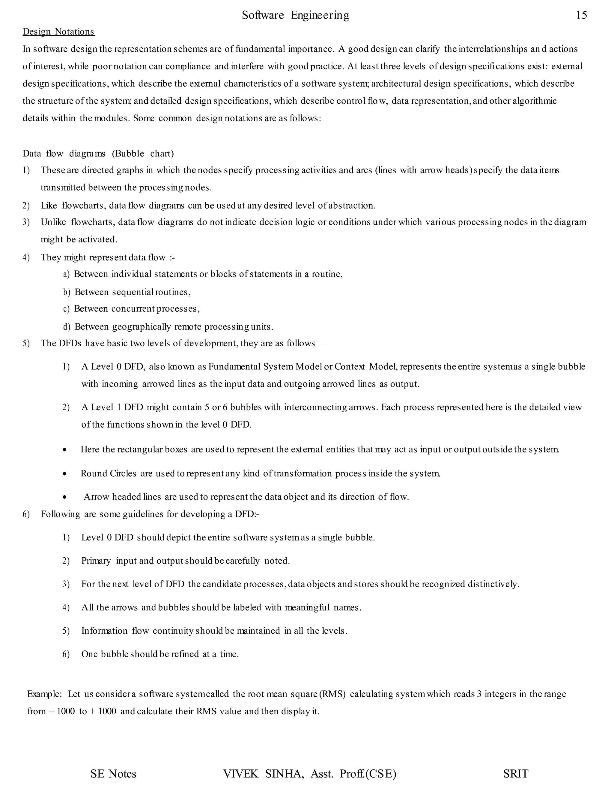
start
For example
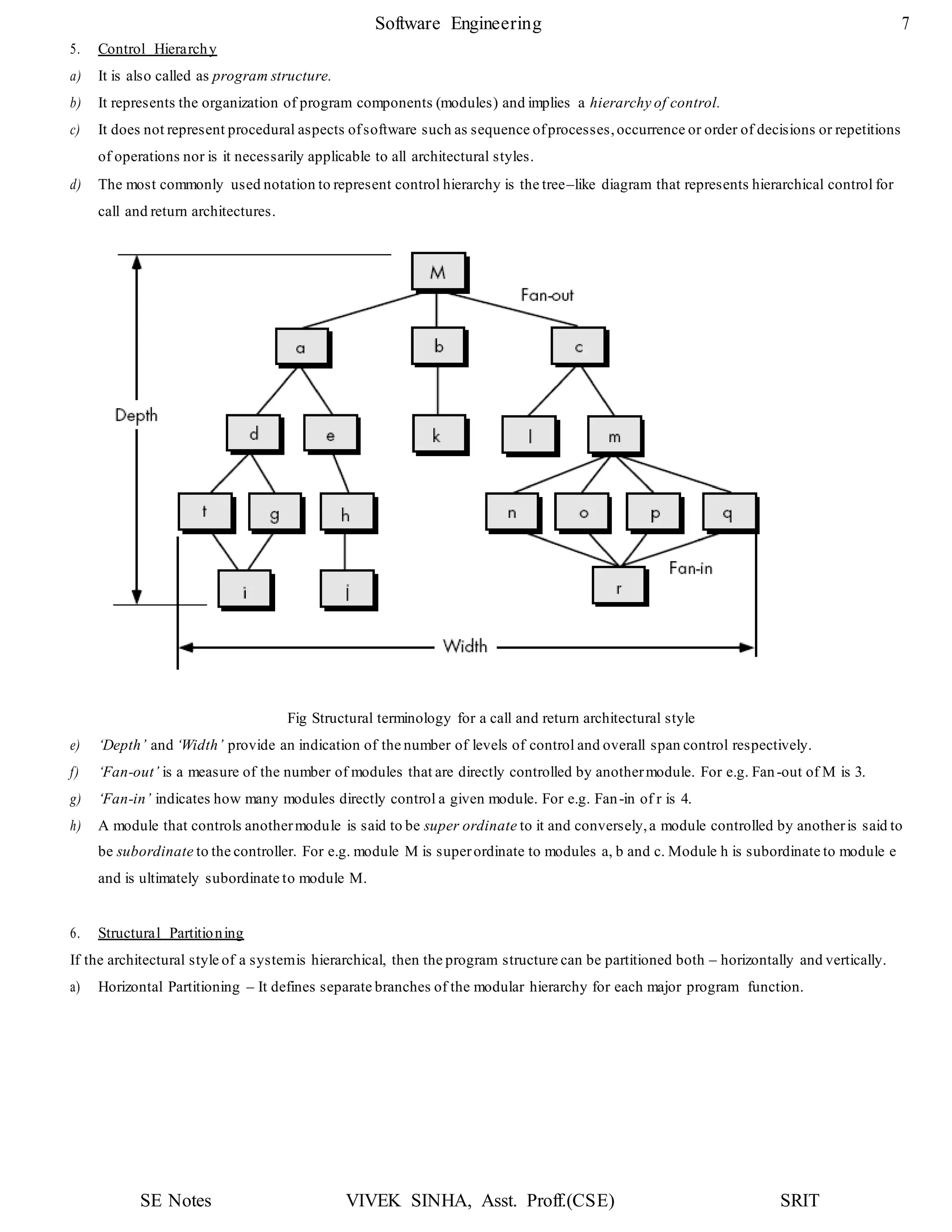
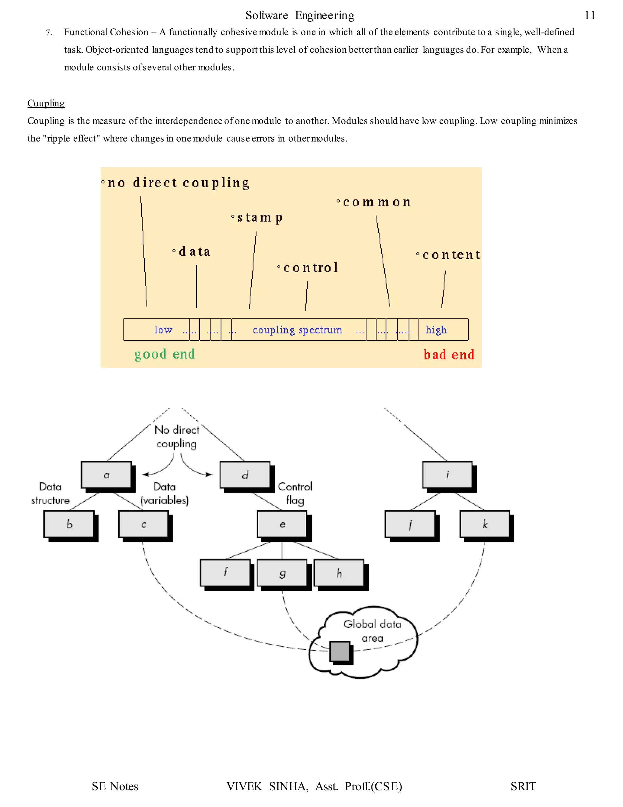
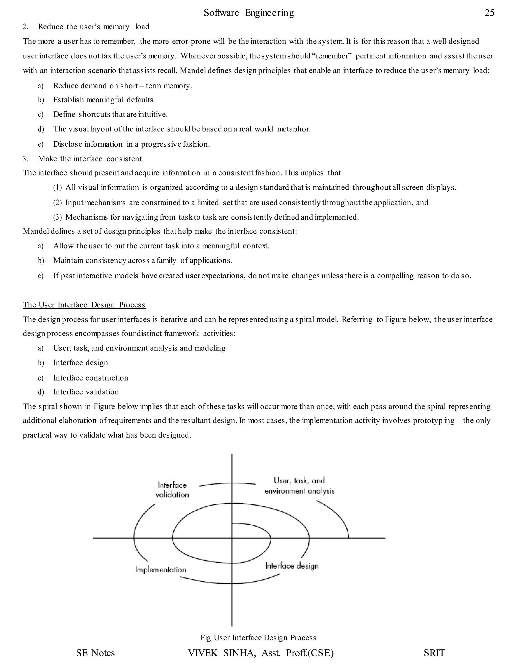
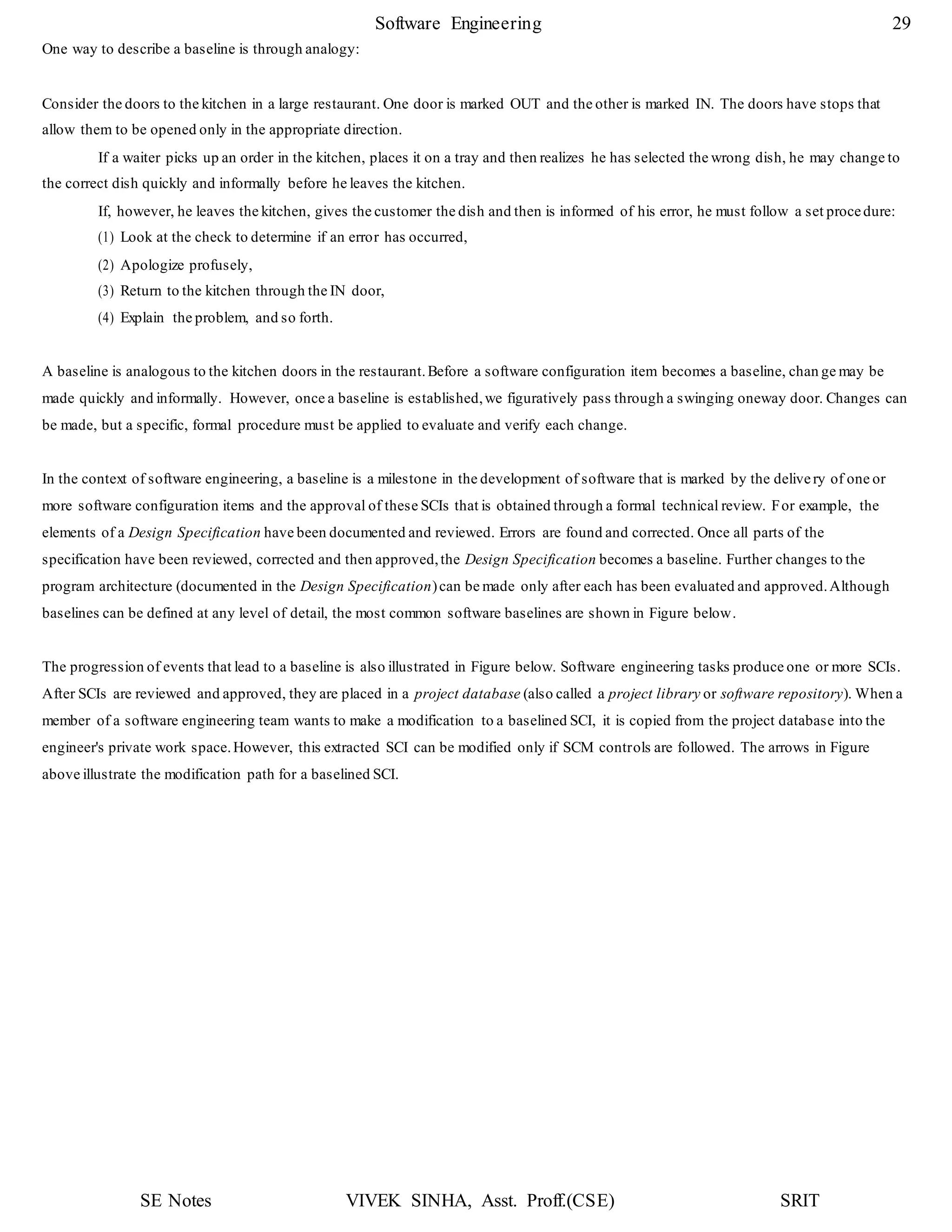
The flow chart of function search is shown below:
Decision tables
Decision tables can be used to specify complex decision logic in a high level software specification. They are also useful for specifying
algorithm logic during detailed design.At this level of usage,decision tables can be specified and translated into source c ode logic.
Pseudocode
Pseudocode notation can be used in both the architectural and detailed design.
It can be used at any desired level of abstraction.
Using pseudocode the designerdescribes systemcharacteristics using short,concise, English language phrases that are structured
by key words such as If- Then-Else, While-Do and End.
Key words and indentation describes the flow of control, while the English phrases describe processing actions.
Pseudocode can replace flowcharts and reduce the amount of external documentation required to describe a system.
Converting pseudocode to a programming language is much easier as compared to converting a flowchart.
i < n
a[i] = =x
flag = = 1
stop
flag = 1
i = i +1
Found
Not
i = 0, flag = 0](https://image.slidesharecdn.com/softwareenggunit3-200318102216/75/Software-engg-unit-3-19-2048.jpg)

![SE Notes VIVEK SINHA, Asst. Proff.(CSE) SRIT
Software Engineering 32
a) Basic object – It’s a “unit of text” created by a software engineer during analysis, design, coding or testing phases.
For example, a basic object might be a section of a requirements specification, a source listing for a component, or a
suite of test cases that are used to exercise the code.
b) Aggregate object – It’s a collection of basic objects and other aggregate objects.
For example, Design Specification is an aggregate object.
Each object has a set of unique features for distinct identification. Every object should have –
i. An unique name,
ii. A description of the object including its SCI type eg. Document, program or data, a project identifier and version
information,
iii. A list of resources,which are entities that are processed,provided or required by the object.
2) Version control – It combines various tools and procedures to manage and control different versions of SCI objects (as a result of
change) that are created during the software engineering process.Clemm describes version control in the context of SCM:
“Configuration management allows a user to specify alternative configurations of the software systemthrough the selection of
appropriate versions.This is supported by associating attributes with each software version, and then allowing a configuration to
be specified [and constructed]by describing the set of desired attributes”.
These "attributes" mentioned can be as simple as a specific version number that is attached to each object or as complex as a
string of Boolean variables (switches) that indicate specific types of functional changes that have been applied to the system.
3) Change control – For a large system development project, uncontrolled change rapidly leads to confusion and inconsistencies.
Change control includes human procedures and automated tools to control the reasons for change. The following processes take
place when a situation of change occurs:
i. Change request – A change request is first submitted and then it is evaluated to asses its –
i) Technical merit,
ii) Potential side effects, subsystems and the cost for implementing the change.
ii. Change report – After the evaluation is done,a change report is created that is submitted to the Change Control
Authority/Board (CCA or CCB). CCA or CCB is a group who are responsible for evaluating the change report and
makes the final decision on the status and priority of the change.This group generates an Engineering Change Order
(ECO) for each approved change.
iii. ECO (Engineering Change Order) – It consists of
i) The description of the change to be made,
ii) Constraints that has to be taken care of and
iii) Criteria for review and audit.
iv. Check out & check in – The object to be changed is “checked out” of the project database,the decided changes are
made and appropriate SQA (Software Quality Assurance)activities are performed. The object is then “checked in” the
project database and appropriate version control mechanisms are used to create the next version of the software.
4) Formal technical reviews (FTR) & Configuration audit – These two activities are required to ensure that the change made to
the software is properly implemented.](https://image.slidesharecdn.com/softwareenggunit3-200318102216/75/Software-engg-unit-3-32-2048.jpg)

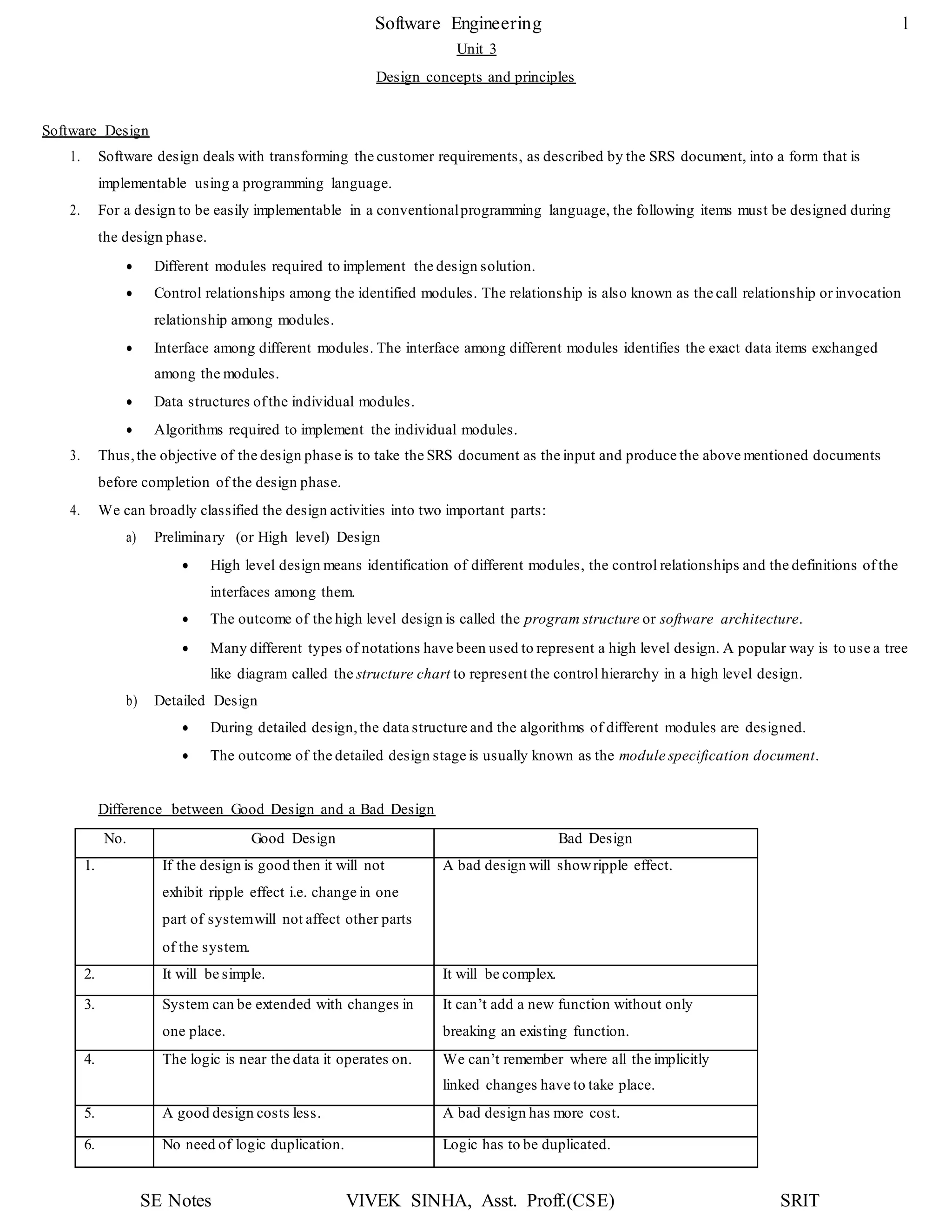
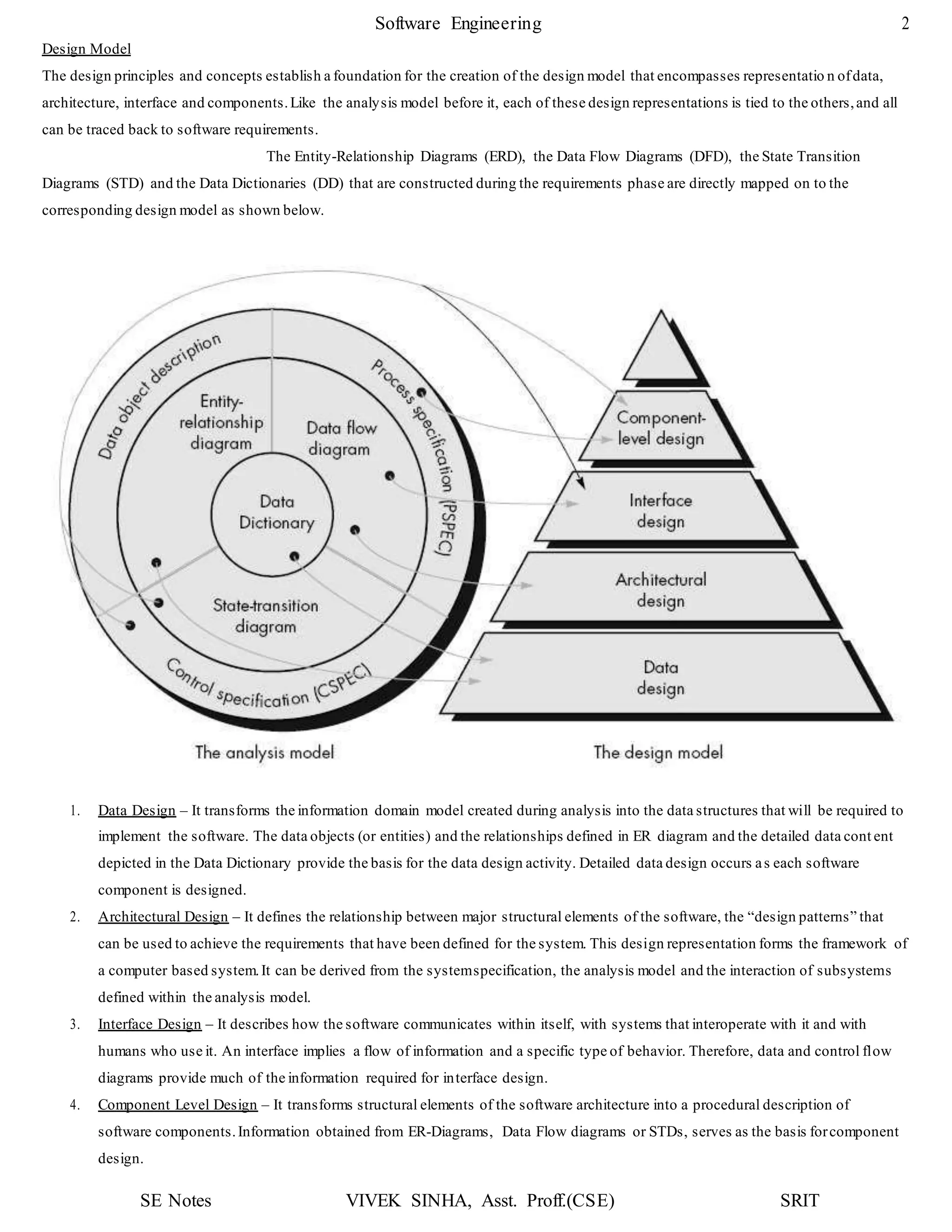
1. The document discusses key concepts in software design including transforming customer requirements into an implementable form, designing modules, control relationships, interfaces, data structures, and algorithms. 2. It also covers preliminary and detailed design phases, where preliminary design identifies modules and relationships, and detailed design specifies data structures and algorithms. 3. Design principles like abstraction, refinement, modularity, architecture, control hierarchy, and information hiding are explained as important concepts for creating a complete design model.