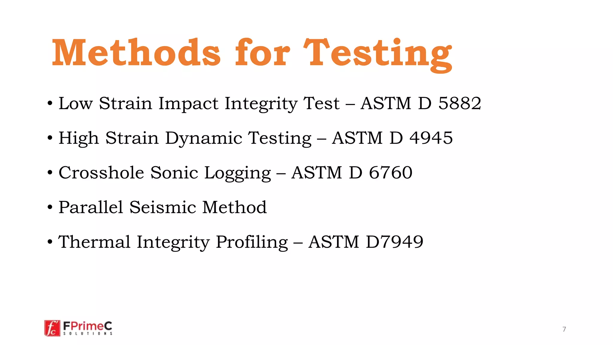
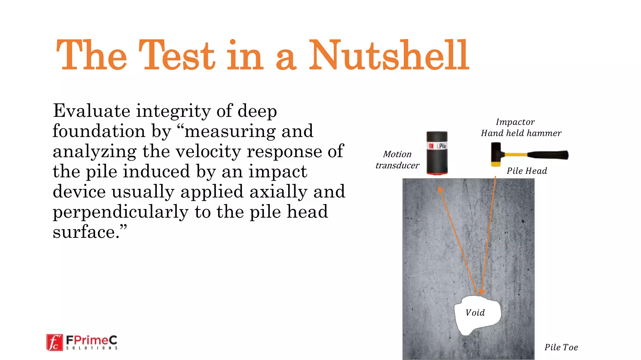
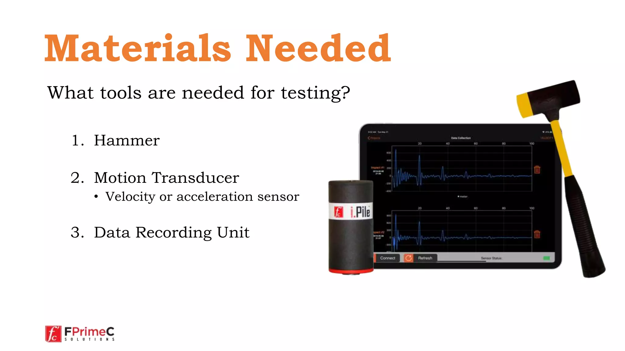
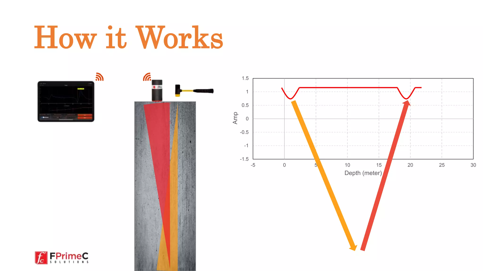
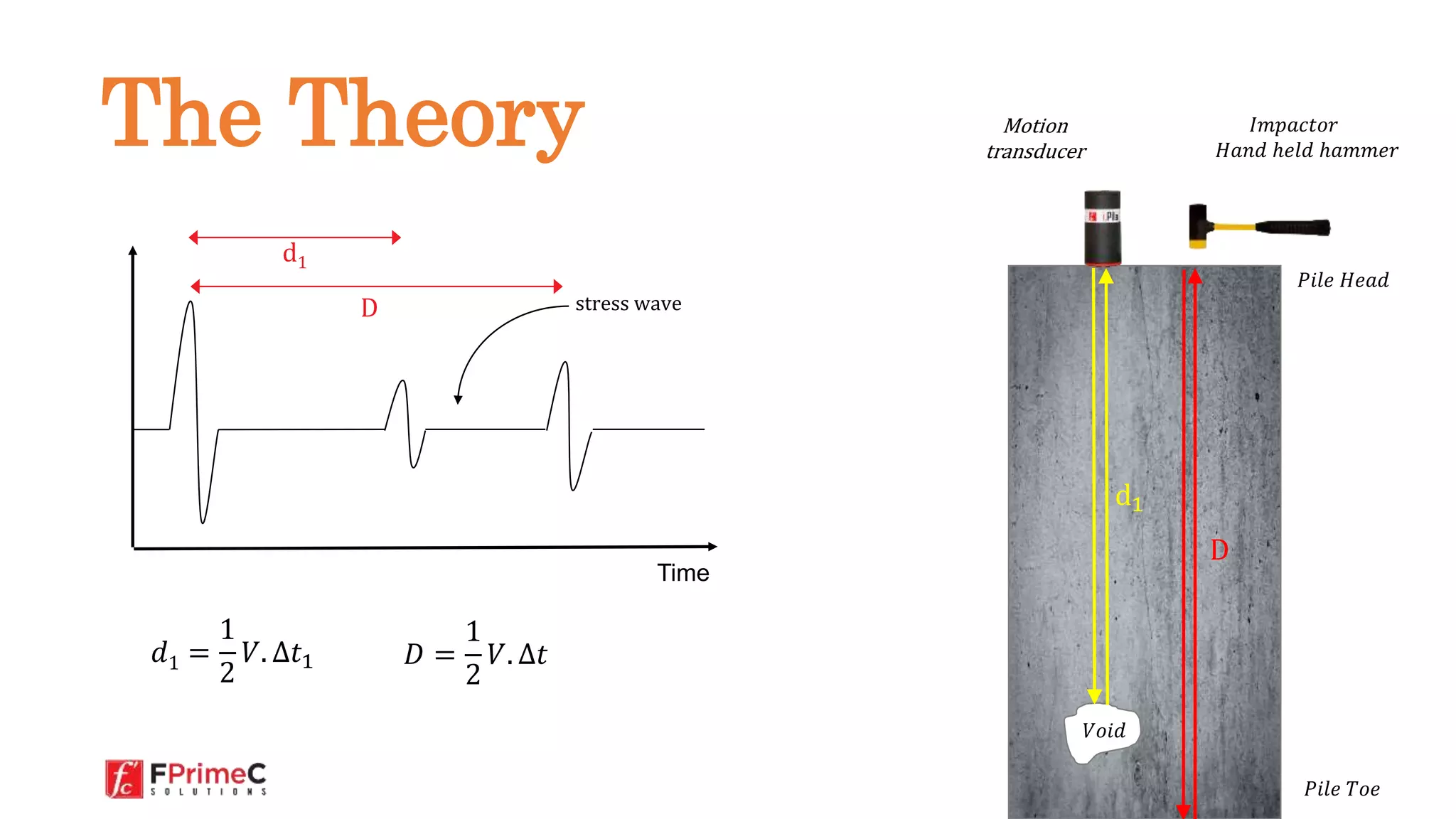
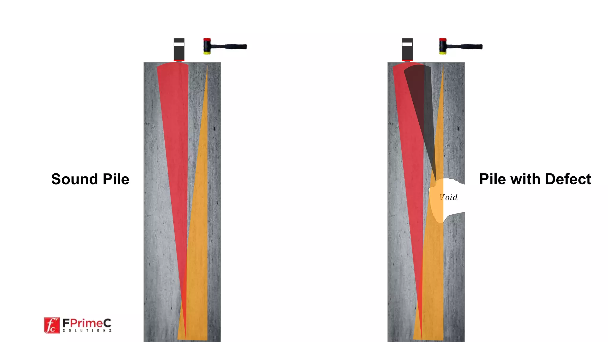
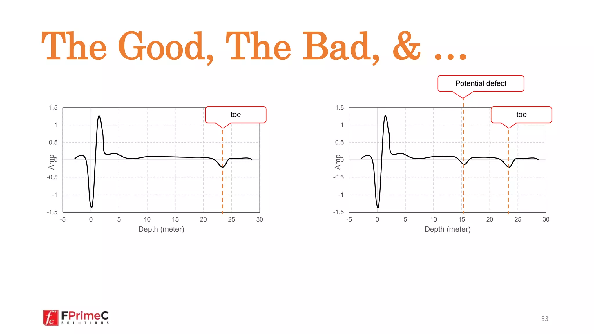
A quick review of low strain impact
tests for deep foundations
What is Pile Integrity?
In This Video
•What is Pile Integrity
•How To Evaluate Pile Integrity
•Low Strain Impact Integrity Test
•Practical Considerations
•Analysis and Reporting
2
“Pile integrity is the qualitative
evaluation of the physical
dimensions, continuity of a pile, and
consistency of the pile material.”
3
Why do we need to test?
4
Sound pile Major Defect Bulging Necking
How to Evaluate Pile Integrity
The theory behind the low strain impact integrity test
6
• Low Strain Impact Integrity Test – ASTM D 5882
• High Strain Dynamic Testing – ASTM D 4945
• Crosshole Sonic Logging – ASTM D 6760
• Parallel Seismic Method
• Thermal Integrity Profiling – ASTM D7949
7
Methods for Testing
The Sonic-Echo Method
8
Low Strain Impact
Integrity Test
The Test in a Nutshell
Evaluate integrity of deep
foundation by “measuring and
analyzing the velocity response of
the pile induced by an impact
device usually applied axially and
perpendicularly to the pile head
surface.”
Motion
transducer
𝑃𝑖𝑙𝑒 𝐻𝑒𝑎𝑑
𝑃𝑖𝑙𝑒 𝑇𝑜𝑒
𝑉𝑜𝑖𝑑
𝐼𝑚𝑝𝑎𝑐𝑡𝑜𝑟
𝐻𝑎𝑛𝑑 ℎ𝑒𝑙𝑑 ℎ𝑎𝑚𝑚𝑒𝑟
What tools are needed for testing?
1. Hammer
2. Motion Transducer
• Velocity or acceleration sensor
3. Data Recording Unit
Motion
transducer
Materials Needed
-1.5
-1
-0.5
0
0.5
1
1.5
-5 0 5 10 15 20 25 30
Amp
Depth (meter)
How it Works
Motion
transducer
𝑃𝑖𝑙𝑒 𝐻𝑒𝑎𝑑
Time
D
𝑑1 =
1
2
𝑉. ∆𝑡1
𝑃𝑖𝑙𝑒 𝑇𝑜𝑒
d1
𝑉𝑜𝑖𝑑
D
d1
𝐷 =
1
2
𝑉. ∆𝑡
𝐼𝑚𝑝𝑎𝑐𝑡𝑜𝑟
𝐻𝑎𝑛𝑑 ℎ𝑒𝑙𝑑 ℎ𝑎𝑚𝑚𝑒𝑟
stress wave
The Theory
• Evaluate integrity and consistency of pile material
• Evaluate unknown length of piles or shafts
• Evaluate pile cross-sectional area and length
13
Applications
• Pile preparation is relatively easy
• The process of testing and data collection is rapid and
inexpensive
• PIT can identify major defects
14
Advantages
• Can not be used to determine the load bearing capacity of
piles
• Interpretation of test results need experience
• Can’t be conducted over the pile cap
• Sensitive length (L) to pile diameter (D) ratio.
• Piles with highly variable cross-section or multiple
discontinuities/anomalies may be difficult to evaluate
15
Disadvantages
Practical Considerations
Some things to consider when testing.
16
You can test 7 days after casting or
after concrete achieve 75% of its
design strength.
17
Timing
Make sure the pile head is:
• Accessible,
• Above water,
• Clean of loose concrete, or soil
18
Surface Preparation
You will need bonding material to
attach the motion transducer. Use a
thin layer wax, petroleum jelly, or
putty.
19
Bonding material
Bonding Material
20
Pile Diameter < 500 mm Pile Diameter > 500 mm
Place sensor at
center
Place sensor at 3
different locations
Pile Placement
Location of
impacts
21
300 mm
Impactor Distance
22
90°
Motion Transducer
Position
When testing, ensure that
• The device is perpendicular to the pile
axis
• The impacts are applied parallel to the
motion transducer
• If individual impacts are recorded, collect at least 10
impacts per pile;
• Rule of thumb: perform 3 blows and use the average for
each record.
• General: The more hammer blows recorded, the greater
reduction in the effects of random noise. The background
noise can be reduced by a factor of √n, where n is the
number of superimposed signals from the same pile.
23
Number of Records
• Light Hammer
• Use for piles less than 1 m
• Less than 1kg
• Heavy Hammer
• Use for larger piles, more than 1m
in diameter
• Should be 1.5 – 6 Kg
Type of Hammer
Data Analysis
Some things to consider when testing.
25
-1.5
-1
-0.5
0
0.5
1
1.5
-5 0 5 10 15 20 25 30
Amp
Depth (meter)
26
Bottom echo
impulse
Pile Integrity Test Record
27
• Motion Transducers collect acceleration or velocity
induced by arriving echoes from the impact to the pile
head
• If an acceleration transducer is used, measurements
should be integrated and displayed in velocity format
• Given the stress wave speed, the time stamp, or
horizontal axis can be converted to depth
Pile Integrity Test Record
• Operators shall monitor the velocity from several impact
events for consistency.
• Do not use the records of impacts that cause the
measurement device to overload (saturated signal with
flat tip).
• Results should be repeatable. If they are not repeatable,
do not use the data. Check sensor placement and
attachment to pile head.
28
Data Quality Check
• Stress wave speed
depends on the quality
of pile material.
• Stress wave speed in
concrete is
approximately 3,600
m/s (medium strength)
to 4,400 m/s (high
quality).
• In most cases, 4,000
m/s (13,000 ft/s) is a
good first guess. 29
-1.5
-1
-0.5
0
0.5
1
1.5
-5 0 5 10 15 20 25 30
Amp
Time // or Depth (meter)
Stress Wave Speed
• Filtering minimizes noise
caused by:
• High frequency reflections
from boundary
• High frequency noise from
sudden or sharp changes in
cross section
• High frequency noise
induced by careless hammer
blow
• A Low Pass filter can be
used to reduce/remove the
effect of high frequency
noise 30
-1.5
-1
-0.5
0
0.5
1
1.5
-5 0 5 10 15 20 25 30
Amp
Time // or Depth (meter)
Filtering
 Amplification is used to
amplify low energy echoes.
 An exponential
amplification function is
applied to amplify the
reflections from pile toe or
defects in deep depths
𝑉𝑎𝑚𝑝 = 𝑉. 𝑒
ln 𝑋.
𝑡
𝑇
 Low Pass filter can be
used to reduce/remove
the effect of high
frequency noise. 31
-3
-2.5
-2
-1.5
-1
-0.5
0
0.5
1
1.5
-5 0 5 10 15 20 25 30
Amp
Time // or Depth (meter)
Amplification function
Amplification
𝑉𝑜𝑖𝑑
Sound Pile Pile with Defect
-1.5
-1
-0.5
0
0.5
1
1.5
-5 0 5 10 15 20 25 30
Amp
Depth (meter)
33
-1.5
-1
-0.5
0
0.5
1
1.5
-5 0 5 10 15 20 25 30
Amp
Depth (meter)
toe toe
Potential defect
The Good, The Bad, & …
 Concrete strength (samples/cores)
 Record pile diameter
 Initial estimation of pile length
 Initial estimation of wave speed in concrete
 Soil profile (soil stratigraphy)
 Construction record, observation
34
Other Information to
Record
 Email: support@fprimec.com
 Tel: +1 (647) 933 6633
 For more information: www.fprimec.com/ipile
FPrimeC Solutions Inc.
300 – 2 Simcoe St. S.
Oshawa, ON, L1H 8C1
35
Have Questions ?

What is Pile Integrity Test ?

  • 1.
    A quick reviewof low strain impact tests for deep foundations What is Pile Integrity?
  • 2.
    In This Video •Whatis Pile Integrity •How To Evaluate Pile Integrity •Low Strain Impact Integrity Test •Practical Considerations •Analysis and Reporting 2
  • 3.
    “Pile integrity isthe qualitative evaluation of the physical dimensions, continuity of a pile, and consistency of the pile material.” 3
  • 4.
    Why do weneed to test? 4
  • 5.
    Sound pile MajorDefect Bulging Necking
  • 6.
    How to EvaluatePile Integrity The theory behind the low strain impact integrity test 6
  • 7.
    • Low StrainImpact Integrity Test – ASTM D 5882 • High Strain Dynamic Testing – ASTM D 4945 • Crosshole Sonic Logging – ASTM D 6760 • Parallel Seismic Method • Thermal Integrity Profiling – ASTM D7949 7 Methods for Testing
  • 8.
    The Sonic-Echo Method 8 LowStrain Impact Integrity Test
  • 9.
    The Test ina Nutshell Evaluate integrity of deep foundation by “measuring and analyzing the velocity response of the pile induced by an impact device usually applied axially and perpendicularly to the pile head surface.” Motion transducer 𝑃𝑖𝑙𝑒 𝐻𝑒𝑎𝑑 𝑃𝑖𝑙𝑒 𝑇𝑜𝑒 𝑉𝑜𝑖𝑑 𝐼𝑚𝑝𝑎𝑐𝑡𝑜𝑟 𝐻𝑎𝑛𝑑 ℎ𝑒𝑙𝑑 ℎ𝑎𝑚𝑚𝑒𝑟
  • 10.
    What tools areneeded for testing? 1. Hammer 2. Motion Transducer • Velocity or acceleration sensor 3. Data Recording Unit Motion transducer Materials Needed
  • 11.
    -1.5 -1 -0.5 0 0.5 1 1.5 -5 0 510 15 20 25 30 Amp Depth (meter) How it Works
  • 12.
    Motion transducer 𝑃𝑖𝑙𝑒 𝐻𝑒𝑎𝑑 Time D 𝑑1 = 1 2 𝑉.∆𝑡1 𝑃𝑖𝑙𝑒 𝑇𝑜𝑒 d1 𝑉𝑜𝑖𝑑 D d1 𝐷 = 1 2 𝑉. ∆𝑡 𝐼𝑚𝑝𝑎𝑐𝑡𝑜𝑟 𝐻𝑎𝑛𝑑 ℎ𝑒𝑙𝑑 ℎ𝑎𝑚𝑚𝑒𝑟 stress wave The Theory
  • 13.
    • Evaluate integrityand consistency of pile material • Evaluate unknown length of piles or shafts • Evaluate pile cross-sectional area and length 13 Applications
  • 14.
    • Pile preparationis relatively easy • The process of testing and data collection is rapid and inexpensive • PIT can identify major defects 14 Advantages
  • 15.
    • Can notbe used to determine the load bearing capacity of piles • Interpretation of test results need experience • Can’t be conducted over the pile cap • Sensitive length (L) to pile diameter (D) ratio. • Piles with highly variable cross-section or multiple discontinuities/anomalies may be difficult to evaluate 15 Disadvantages
  • 16.
    Practical Considerations Some thingsto consider when testing. 16
  • 17.
    You can test7 days after casting or after concrete achieve 75% of its design strength. 17 Timing
  • 18.
    Make sure thepile head is: • Accessible, • Above water, • Clean of loose concrete, or soil 18 Surface Preparation
  • 19.
    You will needbonding material to attach the motion transducer. Use a thin layer wax, petroleum jelly, or putty. 19 Bonding material Bonding Material
  • 20.
    20 Pile Diameter <500 mm Pile Diameter > 500 mm Place sensor at center Place sensor at 3 different locations Pile Placement Location of impacts
  • 21.
  • 22.
    22 90° Motion Transducer Position When testing,ensure that • The device is perpendicular to the pile axis • The impacts are applied parallel to the motion transducer
  • 23.
    • If individualimpacts are recorded, collect at least 10 impacts per pile; • Rule of thumb: perform 3 blows and use the average for each record. • General: The more hammer blows recorded, the greater reduction in the effects of random noise. The background noise can be reduced by a factor of √n, where n is the number of superimposed signals from the same pile. 23 Number of Records
  • 24.
    • Light Hammer •Use for piles less than 1 m • Less than 1kg • Heavy Hammer • Use for larger piles, more than 1m in diameter • Should be 1.5 – 6 Kg Type of Hammer
  • 25.
    Data Analysis Some thingsto consider when testing. 25
  • 26.
    -1.5 -1 -0.5 0 0.5 1 1.5 -5 0 510 15 20 25 30 Amp Depth (meter) 26 Bottom echo impulse Pile Integrity Test Record
  • 27.
    27 • Motion Transducerscollect acceleration or velocity induced by arriving echoes from the impact to the pile head • If an acceleration transducer is used, measurements should be integrated and displayed in velocity format • Given the stress wave speed, the time stamp, or horizontal axis can be converted to depth Pile Integrity Test Record
  • 28.
    • Operators shallmonitor the velocity from several impact events for consistency. • Do not use the records of impacts that cause the measurement device to overload (saturated signal with flat tip). • Results should be repeatable. If they are not repeatable, do not use the data. Check sensor placement and attachment to pile head. 28 Data Quality Check
  • 29.
    • Stress wavespeed depends on the quality of pile material. • Stress wave speed in concrete is approximately 3,600 m/s (medium strength) to 4,400 m/s (high quality). • In most cases, 4,000 m/s (13,000 ft/s) is a good first guess. 29 -1.5 -1 -0.5 0 0.5 1 1.5 -5 0 5 10 15 20 25 30 Amp Time // or Depth (meter) Stress Wave Speed
  • 30.
    • Filtering minimizesnoise caused by: • High frequency reflections from boundary • High frequency noise from sudden or sharp changes in cross section • High frequency noise induced by careless hammer blow • A Low Pass filter can be used to reduce/remove the effect of high frequency noise 30 -1.5 -1 -0.5 0 0.5 1 1.5 -5 0 5 10 15 20 25 30 Amp Time // or Depth (meter) Filtering
  • 31.
     Amplification isused to amplify low energy echoes.  An exponential amplification function is applied to amplify the reflections from pile toe or defects in deep depths 𝑉𝑎𝑚𝑝 = 𝑉. 𝑒 ln 𝑋. 𝑡 𝑇  Low Pass filter can be used to reduce/remove the effect of high frequency noise. 31 -3 -2.5 -2 -1.5 -1 -0.5 0 0.5 1 1.5 -5 0 5 10 15 20 25 30 Amp Time // or Depth (meter) Amplification function Amplification
  • 32.
  • 33.
    -1.5 -1 -0.5 0 0.5 1 1.5 -5 0 510 15 20 25 30 Amp Depth (meter) 33 -1.5 -1 -0.5 0 0.5 1 1.5 -5 0 5 10 15 20 25 30 Amp Depth (meter) toe toe Potential defect The Good, The Bad, & …
  • 34.
     Concrete strength(samples/cores)  Record pile diameter  Initial estimation of pile length  Initial estimation of wave speed in concrete  Soil profile (soil stratigraphy)  Construction record, observation 34 Other Information to Record
  • 35.
     Email: support@fprimec.com Tel: +1 (647) 933 6633  For more information: www.fprimec.com/ipile FPrimeC Solutions Inc. 300 – 2 Simcoe St. S. Oshawa, ON, L1H 8C1 35 Have Questions ?