
Recommended
Recommended
More Related Content
What's hot
What's hot (20)
Similar to Quick return mechanism
Similar to Quick return mechanism (20)
More from Saif al-din ali
More from Saif al-din ali (20)
Recently uploaded
Recently uploaded (20)
Quick return mechanism
- 1. Yadash S Bankay EMT- 1220 Experiment No. 3 Quick Return Mechanism Page 1 of 18 QuickQuickQuick saif alden ali
- 2. Table Of content Cover Page …………………………………………………………………………………..1 Table of Content…………………………………………………………………………..2 Objective………………………………………………………………………………………3 Procedure…………………………………………………………………………………….4 Quick Return Mechanism…………………………………………………………..6-8 Link length vs Stroke…………………………………………………………………….9 Conclusion…………………………………………………………………………………..10 Question…………………………………………………………………………………..11-12 Internet Research Crank Shaper Mechanism…………………………………………………………….13 Quick Return Link…………………………………………………………………………14 Klann (Walking) linkage ……………………………………………………………….15 Double Parallel Crank …………………………………………………………………..16 Crest Spin Electric Toothbrush ……………………………………………………..17 Inductive Charging………………………………………………………………………..18 Page 2 of 18 saif alden ali saif alden ali
- 3. Objectives In this experiment, we will construct a quick return mechanism in order to transform uniform rotation motion on the crank into oscillatory motion of the follower link and linear reciprocating motion of the slider. In other words, the output motion, L R (Left to Right) or R L (Right to Left) will be visible faster than the other one. In addition, by altering the link lengths one at a time we will measure the slider stroke effect, also we are going to plot a graph of the crank angle versus the slider displacement going clockwise and counterclockwise of the crank motion which will be done on a computer. Moreover, we will be able to analyze the degrees crank rotation to determine where the slider will have zero linear velocity and where the slider will have Maximum Linear Velocity using physics terms. Procedure Page 3 of 18 saif alden ali saif alden ali
- 4. The breadboard were on the workbench in a vertical position in order to easily make adjustments. They were three fix pivots, one pivot with dial and two sliding pivots. I assembled the first fixed pivot with the dial in the center of the bread board, and the second pivots at the right extreme and one to the left extreme. Quick Return Starting Position Page 4 of 18 Extreme Left Extreme Right Slider Couple Follower Ground Stroke saif alden ali saif alden ali saif alden ali
- 5. Page 5 of 18 Extreme Right Extreme Left saif alden ali saif alden ali
- 6. Page 6 of 18 Coupler Slider Follower Ground Extreme Right Extreme Left saif alden ali saif alden ali
- 7. Quick Return Mechanism In this experiment, we were required to take data to conform that this is a quick mechanism and how to record the data. I measure the crank angle Vs the slider displacement, starting from zero degrees and increase it 20 ͦ at a time, the I record the data into excel. Crank Angle Vs Slider Displacement Crank Angle CW (Inches) CCW (Inches ) Crank Angle CW (Inches) CCW (Inches ) 0 0 0 200 3.45 3 20 0.125 0.125 220 2.9 2.5 40 0.375 0.5 240 2.25 2 60 0.875 1 260 1.975 1.5 80 1.25 1.5 280 1.5 1 100 1.875 2.1 300 0.875 0.5 120 2.25 2.5 320 0.375 0.3875 140 2.75 2.9 340 0.125 0.125 160 3.25 3.5 360 0 0 180 3.625 3.4 The data was plot using excel graph to analyze the crank angle X-axis Vs the slider displacement Y-axis clockwise and counterclockwise. 0 50 100 150 200 250 300 350 400 0 0.5 1 1.5 2 2.5 3 3.5 4 Crank Angle vs Slider Displacement Crank Angle Vs Slider Displacement CW (Inches) Moving average (Crank Angle Vs Slider Displacement CW (Inches)) Crank Angle Vs Slider Displacement CCW (Inches ) Slider Displacement inches " Crank Angle (Degrease) Page 7 of 18 saif alden ali saif alden ali
- 8. 0 50 100 150 200 250 300 350 400 0 0.5 1 1.5 2 2.5 3 3.5 4 0 0.13 0.38 0.88 1.25 1.88 2.25 2.75 3.25 3.63 3.45 2.9 2.25 1.98 1.5 0.88 0.38 0.13 0 Crank Angle Vs Slider Displacement ClockWise Slider Displacement CW" Crank angle (Degrease) 0 50 100 150 200 250 300 350 400 0 0.5 1 1.5 2 2.5 3 3.5 4 0 0.13 0.5 1 1.5 2.1 2.5 2.9 3.5 3.4 3 2.5 2 1.5 1 0.5 0.39 0.13 0 Crank Angle Vs Slider Displacement Counterclockwisw Slider Displacement CCW" Crank angle (Degrease) As we can see from the diagram above that the length of the crank increase, also there was an increase in the stroke. It is the same aspect for the counts for the ground as long as it increase we can see that the stroke also increase. Page 8 of 18 saif alden ali saif alden ali
- 9. Link lengths Vs Stroke A) As the length of the crank line increase the length of the stroke increase B) As the length of the ground decreases, the length of the stroke increase Alpha α 180 ͦ Beta 360 ͦ- 160 ͦ=200 ͦ Time Ratio= 200/160= 1.25 Second Stroke = 4 22/32 Conclusion Page 9 of 18 Crank (Inches) " Ground (Inches) " Stroke (Inches) "1 1/8 4 4 1/2 1 3/8 4 5 1/2 1 3/8 3 1/4 6 1/2 1 3/8 3 1/4 6 1/2 saif alden ali saif alden ali
- 10. In this experiment, we learn how to construct a quick return linkage to transform uniform rotation motion of the crank into oscillatory rocking motion of the follower link and liner reciprocating motion of the slider. Inclusion, the lab was successful and we have seen that the slider has higher velocity moving to the right to left. Questions 1. The constant angular velocity crank is transform into oscillatory motion for the follower link; also the slider has a linear reciprocating motion. Page 10 of 18 saif alden ali saif alden ali saif alden ali
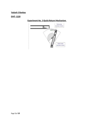
- 11. 2. The time ratio implies that the back and forth slider motion is meant to determine clockwise and counterclockwise which will always be faster than the forward motion since Beta cannot be greater than or equal to the slider. 3. The change of direction for the slider from clockwise to counterclockwise is that the slider value goes up. when the it is flip it is like a mirror image of one another. 0 50 100 150 200 250 300 350 400 Crank Angle vs Slider Displacement Crank Angle Vs Slider Displacement CW (Inches) Moving average (Crank Angle Vs Slider Displacement CW (Inches)) Crank Angle Vs Slider Displacement CCW (Inches ) Slider Displacement inches " Crank Angle (Degrease) 4) 0 50 100 150 200 250 300 350 400 0 0.5 1 1.5 2 2.5 3 3.5 4 0 0.13 0.38 0.88 1.25 1.88 2.25 2.75 3.25 3.633.45 2.9 2.25 1.98 1.5 0.88 0.38 0.13 0 Crank Angle Vs Slider Displacement ClockWise Slider Displacement CW" Crank angle (Degrease) 5) The slider have maximum velocity at 280 ͦ and have zero velocity at 240 ͦ. In addition, the slider higher velocity move from right to left that is because our crank was between 280 ͦ - 300 ͦ Page 11 of 18 saif alden ali saif alden ali saif alden ali
- 12. 6.) The slider crank mechanism and the four bar linkage had graphs that were symmetrical and have two points of maximum velocity. In addition, the Four bar linkage and the quick return mechanism graph is not parabola. Internet Research 1. Crank Shaper Mechanism The shaping machine is used to machine flat metal surfaces especially where a large amount of metal has to be removed. Other machines such as milling machines are much more expensive and are more suited to removing Page 12 of 18 saif alden ali saif alden ali saif alden ali
- 13. smaller amounts of metal, very accurately. The reciprocating motion of the mechanism inside the shaping machine can be seen in the diagram. As the disc rotates the top of the machine moves forwards and backwards, pushing a cutting tool. The cutting tool removes the metal from work which is carefully bolted down. 2. Quick Return linkage -In mechanical design, the designer often has need of a linkage that provides a certain type of motion for the application he/she is designing. Since linkages are the basic building blocks of almost all mechanisms, it is very important to understand how to design linkages for specific design characteristics.https://www.softintegration.com/chhtml/toolkit/mechanism/fou rbar/fourbarQuickReturn.html. Page 13 of 18 saif alden ali saif alden ali saif alden ali
- 14. 3. The Klann linkage is a planar mechanism designed to simulate the gait of legged animal and function as a wheel replacement. The linkage consists of the frame, a crank, two grounded rockers, and two couplers all connected by pivot joints.The proportions of each of the links in the mechanism are defined to optimize the linearity of the foot for one-half of the rotation of the crank. https://en.wikipedia.org/wiki/Klann_linkage Page 14 of 18 saif alden ali saif alden ali saif alden ali
- 15. Double Parallel Crank- A parallelogram system allows a movement similar output to the input movement 4. Page 15 of 18 saif alden ali saif alden ali saif alden ali
- 16. 5. Crest spin Electric Toothbrush The Crest spin electric toothbrush use a 1.5v battery with and electric motor to move a four bar linkage in the toothbrush in order to rotate in the middle of the toothbrush to rotate the brush the top. The spin brush Page 16 of 18 saif alden ali saif alden ali saif alden ali saif alden ali
- 17. pro use a slider crank linkage for the removable brush.http://kmoddl.library.cornell.edu/leonardo/ 6.) Inductive charging (also known as wireless charging) uses an electromagnetic field to transfer energy between two objects. This is usually done with a charging station. Energy is sent through an inductive coupling to an electrical device, which can then use that energy to charge batteries or run the device. Page 17 of 18 saif alden ali saif alden ali saif alden ali
- 18. Page 18 of 18 saif alden ali saif alden ali saif alden ali