
More Related Content
Similar to siphon&HTI 2
Similar to siphon&HTI 2 (20)
More from Dr. Ezzat Elsayed Gomaa
More from Dr. Ezzat Elsayed Gomaa (20)
Recently uploaded
Recently uploaded (20)
siphon&HTI 2
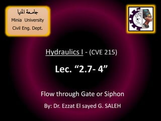
- 1. Minia University Civil Eng. Dept. ـــعةمجا يانملا Flow through Gate or Siphon By: Dr. Ezzat El sayed G. SALEH
- 2. ” داء للك به سطابُي اءود هل .......... الا يداوهيا من يتعأ امحلاقة “
- 3. Sluice Gate – Old Assuit Barrage
- 5. (2) Sluice Gate Geometry Sluice gate of width “W” (1) y1 y2 HGL EGL yG Sluice gates are often used to regulate and measure the flow rate in open channel yG is the gate opening (1) Sectional Elevation Through a Sluice Gate
- 6. (2) Sluice gate of width “W” (1) y1 y2 HGL EGL yG yG is the gate opening (1) Vena-contracta Sectional Elevation Through a Sluice Gate Taking the bed of the channel as a reference datum
- 7. y2 y1 yG Sectional Elevation Through a Sluice Gate yG is the gate opening (1) (2) y3 y
- 8. Radial Gate
- 9. y2 y1 yG y3 Sectional Elevation Through a Radial Gate yG is the gate opening (1) (2) lip
- 10. y2 y1 yG y3 Sectional Elevation Through a Drum Gate yG is the gate opening (1) (2)
- 11. y2 y1 yG Sectional Elevation Through a Drum Gate yG is the gate opening (1) (2) y3 y
- 12. Siphon Liquid
- 14. d (1) (2) Vsiphon H Reference Datum (3) VOrifice h H - h
- 16. Flow Rates ₪ Volume flow rate: is the volume of fluid flowing past a section per unit time. ₪ Mass flow rate: is the mass of fluid flowing past a section per unit time. ₪ Weight flow rate: is the weight of fluid flowing past a section per unit time.
- 17. GB Units SI Units Definition Symbol Name ft3/s m3/s = A V Volume flow rate Slug/s Kg /s = Q = (A V) M Mass flow rate Ibf/s N /s = g Q = g (A V) W Weight flow rate Flow Rates Q
- 18. Time of Empting and Filling
- 19. Atank H1 H2 dh H g 2 A C Q orifice d out 0 Qin dh A dt . Q tank out dh . Q A dt t 0 H H tank 2 1 dh . h g 2 A . C A dt t 0 H H 5 . 0 orifice d tank 2 1 Qout
- 20. Atank H1 H2 dh g 2 V D L f h 2 ) f ( L dh A dt Q tank . dh Q A dt t H H tank . 0 2 1 dh . h g 2 A D L f 5 . 1 A dt t 0 H H 5 . 0 pipe tank 2 1 0 Qin g 2 V2 g V 2 5 0 2 . D L f 5 . 1 g 2 V g 2 V g 2 V D L f g 2 V 5 . 0 h 2 2 2 2 5 . 0 h . D L f 5 . 1 g 2 V 5 . 0 . 5 . 1 2 . . h D L f g A V A Q pipe pipe Q F, L, D V : the velocity through the pipe
- 21. 5 cm 5 cm 5 cm 0.4 cm dia.
- 22. 5 cm 5 cm 5 cm 0.4 cm dia. Water flows from a 10-cm diameter container that contains three holes as shown in the figure. The diameter of each fluid stream is 0.4cm, and the distance between holes is 5cm. If viscous effects are negligible and quasi- steady conditions are assumed. Determine the time at which the water stops draining from the top hole. Compare it with the time required to stop draining from the container. Quasi-steady flow: means that at any moment of time, we can solve the problem as if the flow were steady.
- 25. Siphon
- 26. Irrigation canal & siphon tubes
- 28. 28 Comparison between Absolute and Gage Pressures
- 29. Barometer: instruments used for measuring atmospheric pressure. At sea level the average atmospheric pressure is: 101.3 kPa = 760 mm of mercury = 14.7 psi = 2117 Ib/ft2 Atmospheric Pressure
- 30. Absolute Pressure: is the total pressure measured above zero (perfect vacuum), Gage Pressure: is the pressure measured above atmospheric pressure. Absolute Pressure = gage pressure + atmospheric pressure Suppose that the tire gage measure measures 30 psi (gage), Absolute pressure = 30 psi + 14.7 psi = 44.7psi, Absolute and Gage Pressure
- 31. 4.6 m A 50mm dia. 25mm dia. 0.9 m B water » The volume flow-rate of water from the nozzle. » The pressure at points “A” and “B”. For the siphon shown in the figure, calculate: Worked Example
- 32. 4.6 m A 50mm dia. 25mm dia. 0.9 m B water » Because p1 = p2 = patm. = 0, the remaining terms are 2 1 2 2 1 2 2 2 g V g p Z g V g p Z » Applying Bernoulli’s Equation between points “1” and “2” s m Z Z g V / 5 . 9 6 . 4 0 81 . 9 2 2 2 1 2 Reference Datum » The volume flow rate of water, Q s L V D V A Q / 66 . 4 5 . 9 4 025 . 0 4 2 2 2 2 2 2 Worked Example
- 33. The continuity equation gives: water of m Z g p g p A B 19 . 1 9 . 0 29 . 0 B A g V g p Z g V g p Z 2 2 2 2 s m D D V V siph Siph / 39 . 2 25 50 5 . 9 2 2 . 2 2 . » To determine the pressure at point “A”, apply Bernoulli’s Equation between points “1” and “A” gives, water of m g V g p siph A 29 . 0 81 . 9 2 39 . 2 2 0 2 2 » Similarly, since the siphon cross section is constant (VA =VB), the pressure at point “B” can be determined as, 2 3 3 / 85 . 2 10 81 . 9 10 29 . 0 m kN 2 3 3 / 67 . 11 10 81 . 9 10 19 . 1 m kN Worked Example
- 34. 1.0 m 25mm dia. h water » Does changing the elevation, h, of the siphon centerline above the water level in the tank vary the volume flow-rate through the siphon? Explain. » What is the maximum allowable value of h ? A siphon is used to draw water from a large container as indicated in the figure. Worked Example
- 35. A 7.5cm dia. water » Determine the flow rate involved? A water siphon having a constant inside diameter of 7.5cm is arranged as shown in the figure. If the friction losses between A and B is 0.8 V2/2g, where V is the velocity of flow in the siphon. 1.0 m 1.0 m 3.0 m B Worked Example
- 36. Venturi-meter
- 37. What throat diameter is needed for a Venturi-meter in a 200cm horizontal pipe carrying water with a discharge of 10m3/s if the differential pressure between the throat and upstream section is to be limited to 200kPa at this discharge? (take Cd = 0.98) Solution 4 1 2 2 1 2 2 1 2 4 D D g p p g D C Q d act The basic discharge equation for a Venturi-meter is: m g p 39 . 20 81 . 9 1000 10 200 3 D1 =2.0m = 0.98 10 m3/s ………….. (1) Worked Example
- 38. Eliminating Eq. (1) gives: 2 2 2 16 8 . 6400 13 D D Solving by trial and error: D2 = 0.80m ………….. (2)
- 39. Water flows through a Venturi-meter that has a 30cm throat. The Venturi-meter is installed in a 60cm pipe. What deflection occur in a water-mercury manometer connected between the upstream and throat sections if the discharge of 0.57m3/s. (Cd = 0.98) Solution 4 1 2 2 1 2 2 1 2 4 D D g p p g D C Q d act The basic discharge equation for a Venturi-meter is: D1 =0.60 m = 0.98 0.57 m3/s ………….. (1) 1 / 2 1 i h g p p D2 =0.30 m Worked Example
- 40. For the given case, 6 . 13 0625 . 0 16 1 60 . 0 30 . 0 0706 . 0 4 3 . 0 4 4 4 1 2 2 2 2 2 2 w m L i D D m D A Substituting these values into Eq. (1) gives 0625 . 0 1 1 6 . 13 81 . 9 2 0706 . 0 98 . 0 57 . 0 h ………….. (2) Solving for h, h (the deflection in the manometer) = 25.70cm Worked Example
- 43. Pitot Tube
- 44. What is Pitot tube: Pitot Tube is a device used for measuring the velocity of flow at any point in a pipe or a channel. The Pitot tube was invented by the French Engineer Henri Pitot. The principle of Pitot tube is based on the Bernoulli's equation, where each term can be interpreted as a form of pressure.
- 45. Pitot Tube It is used to measure flow rate at a particular point in a flowing fluid. Such devices are frequently used as air speed indicators in aircraft The Pitot tube consists of a tube with a small opening at the measuring end. This small hole faces the flowing fluid, When the fluid contacts the Pitot tube, the fluid velocity is zero and the pressure is maximum. This small hole or impact opening, provide the higher pressure for pressure measurement. The purpose of the static ports is to sense the true static pressure of the free airstream.
- 46. The true static pressure hole Impact Opening with higher pressure hole Pitot Static tube
- 47. Note: the gray circles outlined in dotted red boxes are Pitot-static ports, which, combined with an aircraft's Pitot tubes
- 48. With no flow, the pressure at both ports is the same and the level in each “leg” of the U-tube is the same. Flow Sensors are typically a Form of Pitot Tube.
- 49. The Pitot tube is used to find the Velocity of a fluid. The parameters for the model include density of fluid “L”, density of manometer liquid (i), differential head (h).
- 51. Laminar flow: slow, organized, parallel to vessel walls, parabolic profile. Vortex flow: swirling, often countercurrent eddies seen at bifurcations and after stenosis Turbulent flow: disorganized, random, with high velocities.
- 52. Types of Flow Laminar Flow Low velocity Particles flow in straight lines No Mixing Rare ( اندرة ) in water system Turbulent Flow High velocity Particles move in irregular paths Mixing Most common type of flow.
- 53. Additional to Weirs By: Dr. Ezzat El-sayed Gomaa SALEH
- 55. Siphon Venturi
- 56. The weir is one of the oldest, cheapest, most straight forward and reliable structures for the determination of flow in channels where sufficient water depth is available. A simple weir consists of a structure in wood, metal or concrete placed perpendicular to the flow in a channel. The structure has a sharp-edged opening or notch of specific shape and dimension through which the water can flow. Weirs are identified by shape as indicated below. Weir
- 57. Rectangular Shape Trapezoidal Shape Triangular Shape Parabolic Shape Circular Shape Shapes of Canal
- 58. Sharp crested weir: (a)Rectangular, (b)Cipoletti or trapezoidal and (c) Triangular or (V- notch). (a) (b) (c)
- 59. Typical Weir Shapes Cipolletti Weir V- notch Weir Rectangular Weir
- 60. Each type of weir has certain advantages under specific conditions. Generally, for accurate readings, a standard V- notch or a rectangular suppressed (parallel sides with no side contractions) weir should be used. The Cipolletti and rectangular weirs with full end contractions are especially suited for water division. Normally the observer has a reasonable idea of the quantities to be measured and taking the following into account, a choice can be made of the suitable weir for particular circumstances: Choice of weir
- 61. The maximum expected water height above the weir must be at least 60 mm to prevent the nape from adhering to the weir crest. Furthermore it is difficult to take accurate readings on the measuring scale if (h) is too low. The length of the rectangular and Cipolletti weirs must be at least equal to three times the water height above the weir crest. The V-notch is the most suitable for measurements smaller than 100 m³/h.
- 62. The V-notch is as accurate as the other weir types for flows between 100 and 1 000 m³/h provided that submergence does not occur. The weir crest must be as high above the channel floor as possible so that free overflow (of the nape) will take place. The flow depth over the weir should not exceed 600 mm.
- 63. When the channel feeding the water to the weir is wider than the weir crest, the sides of the stream will narrow where it crosses the weir. The width of the stream flowing over the weir will be slightly narrower than crest width. The phenomenon is known as end contraction. To make allowance for end contractions, the overflow width in the basic equation must be modified as follows: L' = L – 0.1 n h (8.4) where: L' = effective length of weir [m] L = measured length of weir [m] n = number of end contractions h = overflow depth [m]. End Contractions
- 64. A rectangular weir that does not span the whole channel is called a weir with end contractions. The effective length of the weir will be less than the actual weir length due to contraction of the flow jet caused by the sidewalls. where, N = the number of contractions, and L‘ = measured length of the crest. L = L' – 0.1 n h L'
- 65. A lined channel is provided with a lining of impervious material on its bed and banks to prevent the seepage of water. Lined Canal
- 66. Lined Canal
- 67. Lined Canal
- 68. Advantages of Canal Lining: It reduces the loss of water due to seepage and hence the duty is enhanced, It controls the water logging and hence the bad effects of water-logging are eliminated, It provides smooth surface and hence the velocity of flow can be increased. Advantage of Canal Lining
- 69. Disadvantages of Canal Lining: Higher initial investment, Repair is costly, Shifting of outlet is costly because it involve dismantling and relaying of lining, ( يلهاصتوو نةاالبط تفكيك يشمل نهل ملكف اخملرج نقل نا ) Longer construction period, Sophisticated construction equipment and labor is needed. { هناك حاجة ىلا معدات بناءلا املتطورة العامةلو } Dis - advantage of Canal Lining
- 74. Pumps in Series Volume Flow- rate V . Performance Curve “one pump” Performance Curve “two pump” System Curve A B Head H p When two pumps are placed in series, the resulting pump performance curve is obtained by adding heads at the same flow-rate. As shown in the figure, for two identical pumps in series, both the actual head gained by the fluid and the flow- rate increased, but neither will be doubled if the system curve remains the same. The operating point is at “A” for one pump and moves to “B” for two pumps in series. For two pumps in series, added heads
- 75. Pumps in Parallel Volume Flow- rate V . Performance Curve “one pump” Performance Curve “two pump” System Curve A B Head H p For two identical pumps in parallel, the combined performance curve is obtained by adding flow-rates at the same head. As shown in the figure above, the flow-rate for the system will not be doubled with the addition of two pumps in parallel (if the same system curve applies). However, for a relatively flat system curve (see the shown figure), a significant increase in flow-rate can be obtained as the operating point moves from point “A” to point “B”. For two pumps in parallel, added flow-rates
- 76. y D sin 8 , 2 D A Area 2 , D P perimeter Wetted 4 sin , D P A R raduis hydraulic The h Where is in radians If the section is laid on a constant slope “So”, and the Manning coefficient “n” 3 2 3 5 3 2 3 8 2 1 sin 4 8 , D S n k Q discharge The o The above equation can be written in terms of the flow depth, y, using 2 sin 1 2 D y Uniform Flow in a Circular Section
- 77. V2 = 6m/s V1 = 4m/s V3 10 cm 12 cm 90o The water jets collide and form one homogenous jet as shown in the figure. Determine: » The speed, V, and direction, , of the combined jet. » The loss for a fluid particle flowing from “1” to “3” and from “2” to “3”. Gravity is negligible. Linear Momentum Equation
- 78. V2 = 6m/s V1 = 4m/s V3 10 cm 12 cm 90o V3 cos V3 sin s m Q / 0314 . 0 4 1 . 0 4 3 2 1 s m Q / 0679 . 0 6 12 . 0 4 3 2 2 s m Q Q Q / 1 . 0 0679 . 0 0314 . 0 3 2 1 3 Applying momentum equation in x-direction gives, 2 2 3 3 3 3 2 2 ) ( cos cos 0 V Q V Q A p A p F x Substituting p2 = p3 = patm (gage) and incompressible flow ( is constant), ….. (1) 2 2 3 3 cos V Q V Q 2 2 2 3 2 3 cos A Q A Q or For Q3 = 0.1 m3/s , Q2 = 0.0679 m3/s 2 2 3 2 2 2 3 2 3 2 2 4 1 . 0 0679 . 0 cos D A A A Q Q (2) Linear Momentum Equation
- 79. Applying momentum equation in y-direction gives, 2 1 3 2 2 1 3 2 3 2 1 4 1 . 0 0314 . 0 sin D A A A Q Q ….. (4) 1 1 3 3 3 3 1 1 ) ( sin sin 0 V Q V Q A p A p F x ….. (3) Similarly, Solving Eq. (2) and Eq. (4) for , 2 2 2 1 2 2 10 . 0 12 . 0 0679 . 0 0314 . 0 0679 . 0 0314 . 0 tan D D 308 . 0 10 . 0 12 . 0 0679 . 0 0314 . 0 0679 . 0 0314 . 0 tan 2 2 2 1 2 2 D D and 12 . 17 Linear Momentum Equation
- 80. y2 y1 yG y3 yG is the gate opening (1) (2) Sectional Elevation Through a Radial Gate
- 81. o 5m 35m 20m 5m Hydrostatic Forces “HTI Dec. 2012”
- 82. 20m o 5m 35m 20m 5m Hydrostatic Forces “HTI Dec. 2012” F1 2 cp ) y ( 2 CG ) y ( CG cp 5 m m 77 25 20 25 62 20 y 2 CG . . ) ( m 14 27 62 20 200 77 25 12 62 20 200 77 25 y 3 2 cp . ) . ( . ) / . ( . ) ( o 1 96 . 75 5 20 tan
- 83. Hydrostatic Forces “HTI Dec. 2012” N 10 525 . 24 ) 5 200 ( ) 2 / 5 ( 81 . 9 10 A h g F 6 3 1 1 1 The hydrostatic force on the vertical face of the dam, F1 It acts at a vertical distance = ⅔ 5 =3.33 m below the water surface The hydrostatic force on the inclined face of the dam, F2 N 10 85 . 606 ) 62 . 20 200 ( ) 2 / 20 5 ( 81 . 9 10 A h g F 6 3 2 2 2 cos F F 2 F F F 2 1 2 2 2 1 t = 165.96
- 84. Weight = 250kg Gate Hinge 1.0 m 100 kg 45o Hydrostatic Forces “HTI Dec. 2012”
- 85. 45o 500 mm dia- pinlet = 1000 KN/m2 Linear Momentum Equation “HTI Dec. 2012”
- 86. 45o 500 mm dia- pU.S = 1000 KN/m2 2 0 0 m m d i a - Linear Momentum Equation “HTI Dec. 2012) A reducing pipe bend is shown in the figure. If the discharge is 500L/s and the upstream pressure is1000kN/m2, find the magnitude and direction of the force on the bend. Linear Momentum Equation “HTI Dec. 2012”
- 87. 45o 500 mm dia- P inlet = 103 KN/m2 V1 V2 p1 p2 P2 cos 45o P2 sin 45o C V Linear Momentum Equation “HTI Dec. 2012”
- 88. Section “2” Section “1” P2 in KN P1 in KN A2 in m2 D2 ( m) A1 in m2 D1 ( m) 0.0314 0.20 0.196 0.50 ??? 103 The data given are: To calculate the pressure at the outlet section P2, we use the Bernoulli’s equation. The Bernoulli’s equation for a streamline passing through the centerline of the pipe bend is expressed as 2 2 1 2 g 2 V g p g 2 V g p The pipe bend is in a horizontal position Linear Momentum Equation “HTI Dec. 2012”
- 89. or The inlet and outlet velocities, V1 and V2, may be determined using the continuity equation as g 2 V g 2 V g p g p 2 2 2 1 1 2 ………… (1) s / m 55 . 2 196 . 0 5 . 0 A Q V 1 1 s / m 92 . 15 0314 . 0 5 . 0 A Q V 2 2 and Then, substituting the given data in Eq. (1), water of m 35 . 89 92 . 15 55 . 2 81 . 9 2 1 81 . 9 10 10 10 g p 2 2 3 3 3 2 Linear Momentum Equation “HTI Dec. 2012”
- 90. or Hence, the pressure forces on the pipe bend ends are: 2 3 2 m / kN 53 . 876 35 . 89 81 . 9 10 35 . 89 g p ……… (2) P2 . A2 in KN P1 .A1 in KN 876.530.0314 = 27.52 1030.196 = 196 The reducing pipe bend, surrounded by a suitable control volume, is shown in the figure. The forces acting in the bend are due to the change in direction and the reduction in diameter. Linear Momentum Equation “HTI Dec. 2012”
- 91. The momentum equations along the x- and y- directions are ) V 45 cos V ( Q 45 cos A p A p F 1 2 2 2 1 1 ) x ( …… (3) Substituting the given values, Eq. (3) gives ) 0 45 sin V ( Q 45 sin A p 0 F 2 2 2 ) y ( (where all terms are taken positive with x- and y- axis) ) 55 . 2 45 cos 92 . 15 ( 5 . 0 10 45 cos 10 52 . 27 10 196 F 3 3 3 ) x ( kN 19 . 172 F ) x ( Similarly, Linear Momentum Equation “HTI Dec. 2012”
- 92. Hence ) 0 45 sin 92 . 15 ( 5 . 0 10 45 sin 10 52 . 27 0 F 3 3 ) y ( and kN 09 . 25 F ) y ( kN 174 09 . 25 19 . 172 F F F 2 2 2 ) y ( 2 ) x ( t ' ) x ( ) y ( 17 8 19 . 172 09 . 25 F F From negative x-direction to negative y-direction Then the total force of the elbow on the control volume is 174 KN Fy Fx Ft Linear Momentum Equation “HTI Dec. 2012”
- 93. kN 174 F F t flange on t From Newton’s third law, the force exerts on the bend is the negative of Ft Fx Fy Ft Linear Momentum Equation “HTI Dec. 2012”
- 94. Air S.g. = 0.80 water 0.85 ft 1.60 ft 2.50 ft 4.0 ft 6 . 0 f t The figure shows a container holding oil and water. Air at 710Ibf / ft2 below atmospheric pressure is above the oil. Calculate: ₪ The pressure and force at the bottom of the container in Ibf /ft2 (gage). B The pressure at the bottom of the container 2 f w w oil oil air B ft / Ib 946.13 ) 5 . 2 6 . 1 8 . 0 ( 2 . 32 94 . 1 710 h g h g P P The force at the bottom of the container f B B B Ib 707 22 ) 6 4 ( 13 . 946 A P F Hydrostatic Pressure Forces “HTI Dec. 2012)
- 95. o 5m 35m 20m 5m Hydrostatic Forces “HTI Dec. 2012) A mass concrete dam has the section shown in the figure and spans a channel 200m wide. I) Estimate the magnitude of the resultant force, II) Its angle to the horizontal, and III) The point at which its line of action passes through the base line. Hydrostatic Pressure Forces “HTI Dec. 2012)
- 96. Air S.g. = 0.80 water 0.85 ft 1.60 ft 2.50 ft 4.0 ft