1) The document discusses methods for improving commutation and reducing sparking in single-phase series motors, including reducing the ampere-turns of short-circuited coils, using hard or thin brushes, increasing magnetic reluctance, and adding resistances between the armature winding and commutator.
2) It analyzes the electromotive forces present during commutation, including reactance, resistance, speed, and transformer voltages, and how the flux and currents are affected by short-circuited coils using vector diagrams.
3) The most common modern method is to add resistances in the armature slots to increase the resistance of the short circuit, though this reduces efficiency by increasing losses and temperature
Eet3082 binod kumar sahu lecturer_05 & 6 newBinodKumarSahu5
This document discusses techniques for eliminating harmonic components from the induced electromotive force (emf) waveform in electrical machines. It provides an example calculation of the RMS value and instantaneous value of induced emf containing fundamental, third, and fifth harmonic components. Methods discussed to eliminate harmonics include using a star-connected armature winding to remove triplen harmonics, implementing short-pitched windings, and selecting the short pitch angle to eliminate specific higher harmonics such as the fifth harmonic. The document also examines the effect of short-pitched and distributed windings on the induced emf waveform.
Eet3082 binod kumar sahu lecturer_05 & 6 newBinodKumarSahu5
This document discusses techniques for eliminating harmonic components from the induced electromotive force (emf) waveform in electrical machines. It provides an example calculation of the RMS value and instantaneous value of induced emf containing fundamental, third, and fifth harmonic components. Methods discussed to eliminate harmonics include using a star-connected armature winding to remove triplen harmonics, implementing short-pitched windings to reduce harmonics by introducing a pitch factor, and selecting the short pitch angle to eliminate specific higher harmonics such as the fifth harmonic component. The document also examines how full-pitched and short-pitched windings affect the resultant induced emf.
The document discusses transformers and DC machines. It provides definitions, explanations of principles of operation, parts, types and equations for transformers, DC generators and DC motors. Key points include:
- Transformers transfer power from one circuit to another via electromagnetic induction without changing frequency.
- DC generators convert mechanical energy to electrical energy via the principle of dynamically induced EMF. DC motors operate inversely.
- Transformers, generators and motors each have windings, cores/frames and produce/use magnetic fields in their operation.
- Equations provided relate induced EMF, current, voltage, speed and other variables.
This document discusses alternating current (AC) circuits. It begins by describing how an alternating electromotive force (EMF) is generated using a coil rotating in a magnetic field. Equations are provided showing that both the induced EMF and current vary as sine functions. Common terms used in AC circuits like cycle, frequency, phase, and root mean square (RMS) value are defined. Phasor diagrams are introduced to represent AC quantities in terms of magnitude and direction. Derivations of average and RMS values are shown. Finally, a purely resistive AC circuit is analyzed, showing the current is in phase with voltage and both follow sine waves. Power calculations are also demonstrated.
The document discusses direct current (DC) machines and their operation. It provides details on:
1) The basic components and construction of a DC machine including its armature winding, commutator, and field poles.
2) How an alternating current induced in the armature coils is converted to direct current via the commutator and brush assembly.
3) Different types of armature windings including lap and wave windings.
4) Factors that affect the performance of DC machines such as armature reaction and how it can be mitigated through techniques like using interpoles.
5) Equations for calculating the generated electromotive force (EMF) in a DC generator.
This document discusses synchronous motors and provides information on:
- The key differences between synchronous motors and induction motors, including excitation type, speed, starting capability, and efficiency.
- The advantages of synchronous motors such as ability to operate at lagging or leading power factor and disadvantages like higher cost and need for external excitation.
- The equivalent circuit model of a cylindrical rotor synchronous motor and voltage equation.
- The operation of a synchronous motor at no load and under loaded conditions, explaining how an increase in load causes the rotor to lag the stator by the load angle to draw more current.
- Phasor diagrams showing the voltage and current relationships under lagging and leading power factor operation.
- An example numerical
1. A DC motor converts direct current electrical energy into mechanical energy through electromagnetic induction. It consists of field magnets, an armature, a commutator, and brushes.
2. The motor's working principle is that a current-carrying conductor in a magnetic field experiences a mechanical force based on Fleming's left-hand rule. Back EMF is induced in the armature as it rotates, opposing the applied voltage.
3. A DC motor's speed can be controlled through various methods like adjusting the field flux, armature resistance, or applied voltage. The speed-torque characteristics differ between series, shunt, and compound wound DC motor types.
Power Circuits and Transforers-Unit 1 Labvolt Student Manualphase3-120A
This document discusses fundamentals of electrical circuits, including basic concepts, symbols, and terminology. It covers topics like voltage, current, resistance, and Ohm's law. The document contains detailed information and diagrams about atomic structure, electric fields, resistance of materials, and measuring voltage and current using a data acquisition system. It provides objectives and procedures for an exercise to demonstrate and apply Ohm's law using circuit measurements.
Eet3082 binod kumar sahu lecturer_05 & 6 newBinodKumarSahu5
This document discusses techniques for eliminating harmonic components from the induced electromotive force (emf) waveform in electrical machines. It provides an example calculation of the RMS value and instantaneous value of induced emf containing fundamental, third, and fifth harmonic components. Methods discussed to eliminate harmonics include using a star-connected armature winding to remove triplen harmonics, implementing short-pitched windings, and selecting the short pitch angle to eliminate specific higher harmonics such as the fifth harmonic. The document also examines the effect of short-pitched and distributed windings on the induced emf waveform.
Eet3082 binod kumar sahu lecturer_05 & 6 newBinodKumarSahu5
This document discusses techniques for eliminating harmonic components from the induced electromotive force (emf) waveform in electrical machines. It provides an example calculation of the RMS value and instantaneous value of induced emf containing fundamental, third, and fifth harmonic components. Methods discussed to eliminate harmonics include using a star-connected armature winding to remove triplen harmonics, implementing short-pitched windings to reduce harmonics by introducing a pitch factor, and selecting the short pitch angle to eliminate specific higher harmonics such as the fifth harmonic component. The document also examines how full-pitched and short-pitched windings affect the resultant induced emf.
The document discusses transformers and DC machines. It provides definitions, explanations of principles of operation, parts, types and equations for transformers, DC generators and DC motors. Key points include:
- Transformers transfer power from one circuit to another via electromagnetic induction without changing frequency.
- DC generators convert mechanical energy to electrical energy via the principle of dynamically induced EMF. DC motors operate inversely.
- Transformers, generators and motors each have windings, cores/frames and produce/use magnetic fields in their operation.
- Equations provided relate induced EMF, current, voltage, speed and other variables.
This document discusses alternating current (AC) circuits. It begins by describing how an alternating electromotive force (EMF) is generated using a coil rotating in a magnetic field. Equations are provided showing that both the induced EMF and current vary as sine functions. Common terms used in AC circuits like cycle, frequency, phase, and root mean square (RMS) value are defined. Phasor diagrams are introduced to represent AC quantities in terms of magnitude and direction. Derivations of average and RMS values are shown. Finally, a purely resistive AC circuit is analyzed, showing the current is in phase with voltage and both follow sine waves. Power calculations are also demonstrated.
The document discusses direct current (DC) machines and their operation. It provides details on:
1) The basic components and construction of a DC machine including its armature winding, commutator, and field poles.
2) How an alternating current induced in the armature coils is converted to direct current via the commutator and brush assembly.
3) Different types of armature windings including lap and wave windings.
4) Factors that affect the performance of DC machines such as armature reaction and how it can be mitigated through techniques like using interpoles.
5) Equations for calculating the generated electromotive force (EMF) in a DC generator.
This document discusses synchronous motors and provides information on:
- The key differences between synchronous motors and induction motors, including excitation type, speed, starting capability, and efficiency.
- The advantages of synchronous motors such as ability to operate at lagging or leading power factor and disadvantages like higher cost and need for external excitation.
- The equivalent circuit model of a cylindrical rotor synchronous motor and voltage equation.
- The operation of a synchronous motor at no load and under loaded conditions, explaining how an increase in load causes the rotor to lag the stator by the load angle to draw more current.
- Phasor diagrams showing the voltage and current relationships under lagging and leading power factor operation.
- An example numerical
1. A DC motor converts direct current electrical energy into mechanical energy through electromagnetic induction. It consists of field magnets, an armature, a commutator, and brushes.
2. The motor's working principle is that a current-carrying conductor in a magnetic field experiences a mechanical force based on Fleming's left-hand rule. Back EMF is induced in the armature as it rotates, opposing the applied voltage.
3. A DC motor's speed can be controlled through various methods like adjusting the field flux, armature resistance, or applied voltage. The speed-torque characteristics differ between series, shunt, and compound wound DC motor types.
Power Circuits and Transforers-Unit 1 Labvolt Student Manualphase3-120A
This document discusses fundamentals of electrical circuits, including basic concepts, symbols, and terminology. It covers topics like voltage, current, resistance, and Ohm's law. The document contains detailed information and diagrams about atomic structure, electric fields, resistance of materials, and measuring voltage and current using a data acquisition system. It provides objectives and procedures for an exercise to demonstrate and apply Ohm's law using circuit measurements.
Electrical Technology Notes for preparation.
Kindly note :- Don't forget to use class note book while studying.
Use my theory questions to clear ET and solved all the problems.
armature reaction effect and minimization methodsNayan Solanki
This document discusses armature reaction in DC machines and methods to minimize it. It describes how armature reaction demagnetizes and distorts the main magnetic flux, weakening it in some areas and strengthening it in others. Compensating windings and interpoles are introduced to counteract the cross-magnetizing effect. Commutation, the process of reversing current in armature coils, is also covered. Resistance commutation using carbon brushes and emf commutation using interpoles are two methods discussed to improve commutation and reduce sparking. Interpoles produce a reversing emf that neutralizes reactance voltage during commutation for smooth current reversal.
The document discusses armature reaction and commutation in DC machines. It describes how armature reaction demagnetizes and distorts the main magnetic field, requiring brush shift. Commutation involves the reversal of current in armature coils as they pass between poles. Sparking can occur due to reactance voltage impeding quick current reversal. Methods to improve commutation include resistance commutation using carbon brushes and EMF commutation using interpoles to neutralize reactance voltage.
1. The document summarizes key concepts about AC circuits including sinusoidal waveforms, complex numbers, phasor analysis, complex power, and three-phase AC circuits.
2. Phasor analysis allows AC circuits to be studied in the phasor domain using complex numbers where differential equations are replaced by algebraic equations. Circuit elements like resistors, inductors, and capacitors can be represented by their impedances.
3. Complex power in AC circuits includes both active power P and reactive power Q. Active power represents the energy consumption in the circuit while reactive power is a fictitious power.
This document provides instructions for connecting the windings of a three-phase transformer in delta-delta and wye-wye configurations. It describes verifying the phase relationships by measuring voltages before closing the secondary windings. For a delta connection, the voltage within the closed delta must be zero to avoid high currents. The procedure involves connecting the transformer, measuring voltages to check phase relationships, closing the secondary delta if voltages are correct, and measuring secondary line voltages.
Power Circuits and Transformers-Unit 4 Labvolt Student Manualphase3-120A
The document discusses equivalent inductance for series and parallel inductors. It states that equivalent inductance is greater for series combinations and smaller for parallel combinations, similar to equivalent resistance. Formulas are provided to calculate equivalent inductance for series and parallel configurations. The exercise objective is to determine equivalent inductance using these formulas and circuit measurements of voltage and current.
Power Circuits and Transforers-Unit 8 Labvolt Student Manualphase3-120A
This exercise explores connecting transformers in parallel and measuring their efficiency. Two 100-VA transformers are connected in parallel to supply a 200-VA load. Efficiency is calculated as the ratio of output power to input power. Measurements of input and output power will be taken to determine the overall efficiency and verify that the load is shared between the two transformers. Connecting transformers in parallel allows supplying power greater than the rating of a single transformer.
This document discusses different types of armature windings used in DC motors and generators including lap, wave, simplex, duplex, and triplex windings. It explains the characteristics of each type of winding such as the number of parallel paths through the armature, the relationship between back and front pitch, and how they are connected to the commutator segments. The document also covers closed winding configurations and how they provide multiple parallel paths while maintaining a zero resultant EMF around the complete armature circuit.
Part of a lecture series delivered by me on DC machines to BE Third Year Students, Z. H. College of Engg. & Technology, AMU, Aligarh, 2012-13.
Please comment and feel free to ask anything related. Thanks!
Power Circuits and Transforers-Unit 6 Labvolt Student Manualphase3-120A
This document provides instruction on analyzing balanced three-phase AC circuits connected in wye and delta configurations. It discusses the differences between line and phase voltages and currents. Formulas are presented for calculating active, reactive, and apparent power in balanced three-phase circuits. Exercises are included to measure voltages and currents in wye- and delta-connected resistive loads to verify the theoretical calculations and relationships between line and phase values.
Synchronous motors operate at a constant synchronous speed determined by the supply frequency. They require an external DC excitation source to start and synchronize the rotor speed with the rotating stator magnetic field. Synchronous motors can develop torque through a wide range of speeds and loads, and are well-suited for applications requiring constant speed operation or power factor correction.
Power Circuits and Transformers-Unit 2 Labvolt Student Manualphase3-120A
This document discusses alternating current (AC) and sine waves. It explains that AC voltage continually changes polarity and amplitude, and can be considered a DC voltage that is changing. The frequency of an AC voltage is the number of times per second its polarity changes. Sine waves are well-suited for electrical systems as they allow for efficient power transfer. Key parameters of sine waves include amplitude, frequency, phase, and phase shift. Circuit laws like Ohm's Law apply to AC circuits as well.
This document discusses armature reaction and commutation in DC machines. It defines armature reaction as the effect of armature magnetic flux on the main field flux produced by the stator poles. This causes the magnetic neutral axis to shift and the main flux to weaken. Commutation is defined as the process of reversing the current direction in armature coils as they pass from one pole to the next. Methods to improve commutation include using interpoles and adjusting brush position.
This document provides information about determining the voltage regulation of an alternator using the synchronous impedance or EMF method. It discusses measuring the armature resistance, obtaining the open circuit characteristic (OCC) and short circuit characteristic (SCC) of the alternator. The synchronous impedance is calculated from the OCC and SCC for a given field current. This is used along with the armature resistance to determine the no-load emf and voltage regulation for different load conditions. Two numerical examples are provided to demonstrate calculating the voltage regulation from test data using this method.
This document provides an overview of electrostatics and electric current concepts. It defines electrostatics as electricity from the Greek word for amber, where static electricity is generated by rubbing materials together. The key concepts covered include:
- Coulomb's law which describes the force between electric charges.
- The properties of electric fields and field intensity.
- How capacitors store electric charge and the differences between capacitors connected in parallel versus series.
- Definitions of electric current, resistance, voltage, and potential drop in circuits.
1) Effective current in an AC circuit is 0.707 times the maximum current. Effective voltage is 0.707 times the maximum voltage.
2) Inductive reactance is directly proportional to frequency and inductance. Capacitive reactance is inversely proportional to frequency and capacitance.
3) Impedance is the total opposition to current flow in an AC circuit consisting of resistance and reactance. Power is consumed only by the resistive component of impedance and is proportional to the cosine of the phase angle.
Commutation is the process by which the current in a short circuited coil is reversed as it crosses the MNA. During commutation, the coil is briefly short-circuited. If current reversal from positive to zero to negative is completed by the end of the short circuit period, commutation is ideal. If not completed, sparking can occur in the brushes, making commutation non-ideal. Commutation is illustrated through figures showing the current in a coil decreasing to zero and then reversing as it transitions from one side of the brush to the other during the short circuit period.
This document discusses different types of DC generators, including separately excited, self-excited, shunt, series, and compound generators. It describes the characteristics of shunt generators, including their open circuit characteristics curve and how terminal voltage is affected by load current and armature reaction. The document also defines terms like rated voltage, voltage regulation, residual voltage, and critical resistance. Sample problems are included to demonstrate how to calculate generator voltage based on field current, speed, and load.
Okay, here are the steps to solve this problem:
1) The circuit consists of two resistors (R1 and R2) in series. So we can find the total resistance (Rt) by adding the individual resistances:
Rt = R1 + R2
= 2 Ω + 3 Ω
= 5 Ω
2) Use Ohm's Law to calculate the current drawn (I) from the battery:
V = I × R
5 V = I × 5 Ω
I = 5 V/5 Ω
= 1 A
Therefore, the current drawn from the 5 volt battery is 1 Ampere (1 A).
Here are the answers to the questions on DC generator characteristics:
1. The external characteristic gives the relation between terminal voltage and load current.
2. The three most important characteristics or curves of a DC generator are: the no-load saturation characteristic (E0/If), internal or total characteristic (E/Ia), and external characteristic (V/I).
3. Critical speed of a shunt generator means the speed for which the given shunt field resistance represents critical resistance.
4. One condition necessary for the build-up of a self-excited shunt generator is that there must be some residual magnetism in the generator poles.
5. Some other factors which affect the voltage building of
This chapter discusses a.c. circuits containing resistors, inductors, and capacitors connected in series. It introduces the concepts of reactance and impedance to analyze simple a.c. series circuits. The key learning outcomes are to understand phasor and waveform diagrams for resistance, inductance, and capacitance, and analyze circuits using impedance and power triangles. The chapter also covers power dissipation calculations and introduces the concept of series resonance.
1) An inductor opposes changes in current through self-induction, generating a counter-EMF when current increases or decreases. This causes the current in an AC inductive circuit to lag 90 degrees behind the voltage.
2) Inductive reactance represents an inductor's opposition to AC current, and increases with frequency and inductance. It can be calculated using XL=2πfL.
3) A purely inductive AC circuit does not consume any power on average, as energy stored in the magnetic field during one half of the cycle is returned during the other half.
Universal motors can operate on either AC or DC power. They have high starting torque because the armature and field windings are connected in series. Speed control of a universal motor is achieved by varying the terminal voltage, which changes the current and electromagnetic torque. The motor's angular velocity is determined by solving the differential equation for the electrical system, which depends on the induced back EMF. Back EMF is produced by the motion of the rotor in the magnetic field and opposes the applied voltage, with its magnitude proportional to speed. Varying the applied voltage allows control of the motor's speed and torque.
This document provides an overview of different types of electrical machines including DC machines, synchronous machines, induction machines, and transformers. It begins with the basic construction and operating principles of electrical machines, explaining how they can convert between mechanical and electrical energy. It then discusses DC machines in more detail, covering the construction and working principles of DC generators and DC motors. The document also discusses various types of DC generators including separately excited, self-excited, shunt, series and compound wound generators. Speed control methods for DC motors are also summarized.
Construction and components of DC Machine – Principle of operation – Lap and wave windings-EMF equations– circuit model – armature reaction –methods of excitationcommutation – interpoles compensating winding –characteristics of DC generators.
This document discusses series and parallel circuits. It begins by explaining series circuits, noting that the same current flows through every part of the circuit and the total resistance is calculated by adding individual resistances. It then explains parallel circuits, noting multiple current paths and that individual voltages are equal to the supply voltage. The document provides examples of calculating current, resistance, and voltage in series and parallel circuits. It concludes by discussing practical applications of series and parallel circuits in voltmeters and ammeters.
1) The document discusses the Blondel two-reaction method for analyzing alternators, which separates the armature magnetomotive force (MMF) into sine and cosine components to account for non-uniform air gaps in salient pole machines.
2) It derives an expression for the demagnetizing component of armature reaction, which is proportional to the sine of the angle between voltage and current.
3) It also derives an expression for the cross-magnetizing component of armature reaction, which is proportional to the cosine of the angle between voltage and current.
1) The document presents a transient model of a squirrel cage induction machine that considers the effects of air-gap flux saturation harmonics.
2) The model directly calculates winding fluxes from the air-gap magnetomotive force to avoid using complex inductance harmonics.
3) It incorporates the effects of the fundamental and 3rd harmonic components of the air-gap flux through two saturation models.
4) Simulation results show the model can predict machine transient states and distortions in voltages and currents under saturated conditions.
Alternator,Uses of Alternator ,Working principle ,Basic structure
,Types of Rotor ,Pitch Factor,Distribution Factor,Speed of alternator
,Unity Power Factor ,Zero Power Factor Lagging,Zero Power Factor Leading ,Alternator on Load
This document discusses electromagnetic induction and Faraday's laws of induction. It begins by explaining the relationship between magnetism and electricity, and how changing magnetic flux can induce an electromotive force (emf) in a conductor. It then describes Michael Faraday's experiments in the 1820s and 1830s that led him to formulate his two laws of electromagnetic induction. The first law states that an emf is induced in a conductor whenever the magnetic flux through the conductor changes. The second law relates the magnitude of the induced emf to the rate of change of magnetic flux. The document goes on to discuss examples of dynamically and statically induced emf, and how Lenz's law determines the direction of induced currents. It also covers
This document discusses the operating characteristics of synchronous machines under conditions of variable load and excitation. It examines the power-angle characteristic and phasor diagrams of synchronous machines in generating and motoring modes. The machine behavior is analyzed at constant load with variable excitation, showing that the power angle varies to keep real power constant as excitation changes. Minimum excitation is defined as the stability limit where the power angle reaches 90 degrees. In summary, real power depends on mechanical input while excitation controls only power factor in a synchronous machine.
1) The document discusses the equivalent circuit of an alternator and how to determine the induced emf and voltage regulation.
2) The equivalent circuit accounts for armature resistance, synchronous reactance due to armature reaction, and leakage reactance.
3) Voltage regulation is defined as the percent change in terminal voltage from no-load to full-load conditions with constant field current and speed. It can be positive, zero, or negative depending on the load power factor.
The document discusses different types of AC and DC motor starters and electronics components. For AC motors, it describes DOL starter, star-delta starter, and auto transformer starter. For DC motors, it mentions three point starter and four point starter. It then provides an overview of semiconductor components used in electronics like semiconductors, diodes, transistors, SCRs, LEDs, and basic rectifier circuits.
1) The internal generated voltage (EA) in a synchronous generator is different from the output voltage (Vφ) due to armature reaction, self-inductance, and resistance of the stator coils.
2) Armature reaction, caused by the distortion of the air-gap magnetic field by the stator current, is the largest effect. It can be modeled by an inductor in series with EA.
3) The full equivalent circuit model of a 3-phase synchronous generator includes a DC power source for the rotor field, and a per-phase equivalent circuit with EA in series with resistance and inductance to represent the combined effects of armature reaction and self-inductance.
Transformer wikipedia, the free encyclopediaBibek Chouhan
The document summarizes key aspects of transformers:
1. Transformers transfer energy through inductive coupling between winding circuits, with a varying current in the primary winding creating a varying magnetic flux that induces a voltage in the secondary winding.
2. Transformers range in size from small units in microphones to large units connecting power grids. They are essential for transmission, distribution and use of electrical energy.
3. An ideal transformer induces a secondary voltage proportionate to the primary voltage and winding turn ratios, with no losses. Real transformers have additional factors like core losses, winding impedances and leakage flux.
Transformer wikipedia, the free encyclopediaBibek Chouhan
The document summarizes key information about transformers:
- Transformers transfer energy through inductive coupling between winding circuits. A changing current in the primary winding creates a changing magnetic field that induces a voltage in the secondary winding.
- Transformers come in various sizes, from thumb-sized to units weighing hundreds of tons used in power grids. They are essential for transmitting, distributing, and utilizing electrical energy.
- An ideal transformer transfers power without losses according to turns ratio. Real transformers have losses from winding resistance, leakage flux, and magnetic core properties like hysteresis and eddy currents.
The back emf is an induced voltage in the armature of a DC motor that opposes the applied voltage according to Lenz's Law. The magnitude of the back emf can be calculated using the formula provided, and is always less than the applied voltage. The relationship between the applied voltage, back emf, armature current, and armature resistance is V = Eb + IaRa, where V is the applied voltage, Eb is the back emf, Ia is the armature current, and Ra is the armature resistance.
Wind parks are made up of a large number of
saturable inductances (power transformers, inductive voltage
transformers (IVTs)), as well as capacitors (cables, wind turbine
harmonic filters, capacitor voltage transformers (CVTs), voltage
grading capacitors in circuit-breakers). Therefore, they may
present scenarios in which ferroresonance occurs. This paper
presents the scenarios that can lead to ferroresonant circuits in
doubly fed induction generator (DFIG) based wind parks.
The document discusses the autotransformer, which can be considered as a special case of either a transformer or a single-winding coil with an iron core. It has a single winding wound on the core, but with four terminals - two for each circuit. This gives it common characteristics with a transformer. The document analyzes the structure, operation principles, equivalent circuits, losses, efficiency and three-phase connections of autotransformers. It explains that autotransformers can reduce size and costs compared to standard transformers for the same power rating, though they have some disadvantages to consider for the application.
Similar to Single phase alternator by Nikola Tesla (20)
Automatic Power Factor Detection And Correction using ArduinoSouvik Dutta
Automatic Power Factor Detection And Correction using Arduino as pername sujjest makes a Arduino based project detecting power factor of running loads in a system and correcting them .It can display running power factor on its lcd screen and compensated value of power factor .capacitors bank used to minimize power factor deflection from unity s most of the loads are inductive.
Generator synchronization is the process of matching the frequency and phase of an incoming generator to a busbar before connecting the two. Several lamp methods are used to check synchronization by observing the flickering of lamps connected across the generator and busbar phases. The dark lamp method uses three lamps, where synchronizing occurs when the lamps flicker and go dark together at the same time. The three bright lamp method connects the lamps across non-corresponding phases, and synchronizing occurs when the lamps brighten and dim together. The two bright one dark lamp method connects one lamp directly across phases and two lamps across non-corresponding phases, with synchronizing when the straight lamp is dark and cross lamps are bright.
This document provides information about a book on electrical machines published by Nodia & Company. It contains sample questions and answers from previous years' GATE exams on the topic of electrical machines. The document notes that the information is obtained from sources believed to be reliable but the publisher does not guarantee accuracy. It is intended as a study guide and not for rendering professional engineering services. The publisher information and copyright are also provided.
Doping introduces impurities into a semiconductor crystal to modify its conductivity. N-type doping uses elements with 5 valence electrons like phosphorus, which provides an extra electron that is loosely bound and can move freely. P-type doping uses elements with 3 valence electrons like boron, which accepts an electron from the semiconductor, leaving behind a positively charged hole. Both doping types increase the number of charge carriers, with n-type providing free electrons and p-type providing free holes. This allows control over whether the semiconductor behaves as an electron or hole conductor.
Fundamental elements of-electrical-engineering circuit theory basic stardeltaSouvik Dutta
The document discusses various topics related to magnetism. It defines key terms like magnetic pole, magnetic axis, and pole strength. It describes different types of magnets such as natural magnets, permanent magnets, and electromagnets. Permanent magnets retain their magnetic properties indefinitely, while electromagnets only exhibit magnetism when electric current is passed through them. Electromagnets are widely used in applications like electric generators, motors, cranes and medical devices due to their adjustable magnetic field strength. Soft iron can be magnetized temporarily using an electromagnet, while steel retains magnetism and is used to make permanent bar magnets.
This document discusses the risk of steam turbine damage from reverse power or anti-motoring. It provides an example where a steam turbine experienced mechanical damage after a generator it was connected to drove the turbine like a synchronous motor for 20 minutes following a power disconnection from the network. Key contributing factors were a failure of the anti-motoring protection relay and lack of dedicated electrical technicians during commissioning. It recommends annual testing of anti-motoring protection systems and training operators on identifying generator motoring conditions and shutdown procedures.
This document discusses faults on electrical systems. It begins with an acknowledgement section thanking those who helped with the research. It then provides an abstract stating that faults cause unbalances in three-phase systems and can now be prevented using digital or analog protection techniques. The document proceeds to cover topics like transient stability, sequence networks, fault types including single line-to-ground, line-to-line, double line-to-ground and three phase faults. It discusses fault points and symmetrical components including positive, negative and zero sequences. The methodology section describes how to analyze unbalanced faults using bus impedance matrices for different fault types like single line-to-ground, line-to-line and double line-to-ground
This document provides an overview of a Department of Energy handbook on engineering symbology, prints, and drawings. It discusses electronic diagrams and schematics. The module introduces electronic schematic drawing symbology and provides examples of electronic schematic diagrams. It also discusses how to read electronic prints, diagrams, and schematics. Additionally, it introduces block drawing symbology and provides examples of block diagrams. The overview aims to provide personnel with a foundation for reading, interpreting, and using engineering prints and drawings.
The document provides an overview of engineering prints and drawings, including:
- The typical components of drawings such as the title block, grid system, and revision block.
- The main categories of drawings like piping and instrumentation diagrams, electrical schematics, and fabrication drawings.
- Views and perspectives commonly used in drawings such as orthographic, isometric, and exploded views.
Energy efficient-electric-motor-selection-handbookSouvik Dutta
This document provides a summary of a handbook that was created to help industry identify opportunities to save energy and costs through the use of energy-efficient electric motors. The handbook covers the economic and operational factors to consider when purchasing motors, and includes a motor performance database and guidance on conducting a motor improvement program. It was funded by the Bonneville Power Administration to promote conservation in the industrial sector, where electric motors are large energy users.
The document provides information on the competency-based curriculum for the trade of Electrician under the Craftsman Training Scheme (CTS) in semester pattern. It discusses the job roles of an Electrician, which includes installing, maintaining, and repairing electrical equipment and fittings. It also lists the National Occupational Standards (NOS) and National Classification of Occupations (NCO) codes that are applicable to the role. The curriculum aims to align the qualification with the National Skills Qualification Framework (NSQF) at level 4. It provides details on the learning outcomes, course structure, syllabus, assessment standards and infrastructure requirements for the training.
Electrical power supply and distributionSouvik Dutta
This document is a technical manual that provides guidance on electrical power supply and distribution systems for the Army and Air Force. It covers topics such as voltage selection, main electric supply stations/substations, aerial and underground distribution lines. The manual establishes standards and procedures for designing, evaluating, and selecting electrical power systems to ensure reliable and efficient power delivery to military installations.
1) This guide provides information to help design protection systems for electrical power networks. It discusses power system architectures, neutral earthing systems, short circuits, sensors, protection functions, and discrimination techniques.
2) The guide has two parts: the first discusses theoretical aspects of power system studies, while the second provides solutions for protecting different applications such as transformers, motors, and generators.
3) Protection systems aim to safely detect and clear faults while maintaining continuity of power supply. Proper coordination of protection devices is important to isolate only the faulty sections of the network.
This document is an electrical installation handbook that provides guidance on selecting and dimensioning electrical system components. It covers standards for electrical installations, protection of feeders and equipment, power factor correction, protection of humans, short circuit current calculation, and calculation tools. The handbook aims to supply tables and selection criteria for common electrical plant design situations in a single reference document.
The document discusses standards related to electrical installations, including IEC standards, European directives such as the Low Voltage Directive and EMC Directive, and standards organizations such as IEC, CENELEC, and national standards bodies. It covers the purpose of standards, key directives governing electrical equipment in Europe, conformity markings, and naval certification standards for equipment used in marine environments.
The document provides formulas and definitions for basic electrical engineering concepts. It includes formulas for resistance, inductance, capacitance, impedance, and energy for series and parallel circuits. Kirchhoff's laws and Ohm's law are defined. Maxwell's equations in free space are listed. Magnetic field units and equations are given, including for magnetic induction, field strength, flux, magnetization, and permeability. Formulas are provided for inductance, emf, and magnetic circuits. Definitions include SI and CGS units with conversion factors.
This document discusses synchronous motors and generators. It begins by providing details about a large synchronous motor that was used to power the ocean liner Queen Elizabeth 2. It then discusses the construction and operation of synchronous motors, noting that their rotors lock with the rotating magnetic field from the stator. The document continues by describing the construction of synchronous generator/alternator stators and rotors. It provides equations for synchronous speed and induced electromotive force in an alternator. The document concludes by discussing methods for determining the voltage regulation of synchronous generators.
1) A synchronous generator produces AC voltage through induction in its stator windings caused by a rotating magnetic field generated by its rotor. The rotor contains field windings energized by DC current to produce the magnetic field.
2) The internal generated voltage of the generator depends on its rotational speed and magnetic flux. However, armature reaction and impedance effects cause the terminal voltage to differ from the internal voltage under load conditions.
3) Equivalent circuits are used to model synchronous generators, representing the internal generated voltage and impedance effects. Phasor diagrams illustrate the relationship between voltages and currents under different load power factors.
Earthing of mv and lv distribution linesSouvik Dutta
1) Earthing and bonding of power distribution systems requires balancing safety, reliability, and various fault conditions. Factors like step and touch potentials, fault clearing, lightning protection, and wood pole damage must be considered.
2) Transferring ground potential rise voltages from the MV system to the LV system can be lethal, so the paper focuses on optimally bonding wood poles that carry MV, LV, and other services.
3) Environmental factors like lightning, pollution, and wood properties influence earthing and bonding design choices to prevent equipment and pole damage while maintaining reliability.
Determining correction factor of power cable sizingSouvik Dutta
This document is a thesis submitted by Muhammad Mokhzaini Bin Azizan to fulfill the requirements for a Master of Science degree in December 2008. It acknowledges those who provided guidance and support during the research. The thesis examines determining the correction factor of power cable sizing under nonlinear load conditions. It includes chapters on the introduction, literature review, experiment methodology, experimental results and discussions, and conclusions.
Comparative analysis between traditional aquaponics and reconstructed aquapon...bijceesjournal
The aquaponic system of planting is a method that does not require soil usage. It is a method that only needs water, fish, lava rocks (a substitute for soil), and plants. Aquaponic systems are sustainable and environmentally friendly. Its use not only helps to plant in small spaces but also helps reduce artificial chemical use and minimizes excess water use, as aquaponics consumes 90% less water than soil-based gardening. The study applied a descriptive and experimental design to assess and compare conventional and reconstructed aquaponic methods for reproducing tomatoes. The researchers created an observation checklist to determine the significant factors of the study. The study aims to determine the significant difference between traditional aquaponics and reconstructed aquaponics systems propagating tomatoes in terms of height, weight, girth, and number of fruits. The reconstructed aquaponics system’s higher growth yield results in a much more nourished crop than the traditional aquaponics system. It is superior in its number of fruits, height, weight, and girth measurement. Moreover, the reconstructed aquaponics system is proven to eliminate all the hindrances present in the traditional aquaponics system, which are overcrowding of fish, algae growth, pest problems, contaminated water, and dead fish.
Introduction- e - waste – definition - sources of e-waste– hazardous substances in e-waste - effects of e-waste on environment and human health- need for e-waste management– e-waste handling rules - waste minimization techniques for managing e-waste – recycling of e-waste - disposal treatment methods of e- waste – mechanism of extraction of precious metal from leaching solution-global Scenario of E-waste – E-waste in India- case studies.
Understanding Inductive Bias in Machine LearningSUTEJAS
This presentation explores the concept of inductive bias in machine learning. It explains how algorithms come with built-in assumptions and preferences that guide the learning process. You'll learn about the different types of inductive bias and how they can impact the performance and generalizability of machine learning models.
The presentation also covers the positive and negative aspects of inductive bias, along with strategies for mitigating potential drawbacks. We'll explore examples of how bias manifests in algorithms like neural networks and decision trees.
By understanding inductive bias, you can gain valuable insights into how machine learning models work and make informed decisions when building and deploying them.
Use PyCharm for remote debugging of WSL on a Windo cf5c162d672e4e58b4dde5d797...shadow0702a
This document serves as a comprehensive step-by-step guide on how to effectively use PyCharm for remote debugging of the Windows Subsystem for Linux (WSL) on a local Windows machine. It meticulously outlines several critical steps in the process, starting with the crucial task of enabling permissions, followed by the installation and configuration of WSL.
The guide then proceeds to explain how to set up the SSH service within the WSL environment, an integral part of the process. Alongside this, it also provides detailed instructions on how to modify the inbound rules of the Windows firewall to facilitate the process, ensuring that there are no connectivity issues that could potentially hinder the debugging process.
The document further emphasizes on the importance of checking the connection between the Windows and WSL environments, providing instructions on how to ensure that the connection is optimal and ready for remote debugging.
It also offers an in-depth guide on how to configure the WSL interpreter and files within the PyCharm environment. This is essential for ensuring that the debugging process is set up correctly and that the program can be run effectively within the WSL terminal.
Additionally, the document provides guidance on how to set up breakpoints for debugging, a fundamental aspect of the debugging process which allows the developer to stop the execution of their code at certain points and inspect their program at those stages.
Finally, the document concludes by providing a link to a reference blog. This blog offers additional information and guidance on configuring the remote Python interpreter in PyCharm, providing the reader with a well-rounded understanding of the process.
ACEP Magazine edition 4th launched on 05.06.2024Rahul
This document provides information about the third edition of the magazine "Sthapatya" published by the Association of Civil Engineers (Practicing) Aurangabad. It includes messages from current and past presidents of ACEP, memories and photos from past ACEP events, information on life time achievement awards given by ACEP, and a technical article on concrete maintenance, repairs and strengthening. The document highlights activities of ACEP and provides a technical educational article for members.
CHINA’S GEO-ECONOMIC OUTREACH IN CENTRAL ASIAN COUNTRIES AND FUTURE PROSPECTjpsjournal1
The rivalry between prominent international actors for dominance over Central Asia's hydrocarbon
reserves and the ancient silk trade route, along with China's diplomatic endeavours in the area, has been
referred to as the "New Great Game." This research centres on the power struggle, considering
geopolitical, geostrategic, and geoeconomic variables. Topics including trade, political hegemony, oil
politics, and conventional and nontraditional security are all explored and explained by the researcher.
Using Mackinder's Heartland, Spykman Rimland, and Hegemonic Stability theories, examines China's role
in Central Asia. This study adheres to the empirical epistemological method and has taken care of
objectivity. This study analyze primary and secondary research documents critically to elaborate role of
china’s geo economic outreach in central Asian countries and its future prospect. China is thriving in trade,
pipeline politics, and winning states, according to this study, thanks to important instruments like the
Shanghai Cooperation Organisation and the Belt and Road Economic Initiative. According to this study,
China is seeing significant success in commerce, pipeline politics, and gaining influence on other
governments. This success may be attributed to the effective utilisation of key tools such as the Shanghai
Cooperation Organisation and the Belt and Road Economic Initiative.
Batteries -Introduction – Types of Batteries – discharging and charging of battery - characteristics of battery –battery rating- various tests on battery- – Primary battery: silver button cell- Secondary battery :Ni-Cd battery-modern battery: lithium ion battery-maintenance of batteries-choices of batteries for electric vehicle applications.
Fuel Cells: Introduction- importance and classification of fuel cells - description, principle, components, applications of fuel cells: H2-O2 fuel cell, alkaline fuel cell, molten carbonate fuel cell and direct methanol fuel cells.
Optimizing Gradle Builds - Gradle DPE Tour Berlin 2024Sinan KOZAK
Sinan from the Delivery Hero mobile infrastructure engineering team shares a deep dive into performance acceleration with Gradle build cache optimizations. Sinan shares their journey into solving complex build-cache problems that affect Gradle builds. By understanding the challenges and solutions found in our journey, we aim to demonstrate the possibilities for faster builds. The case study reveals how overlapping outputs and cache misconfigurations led to significant increases in build times, especially as the project scaled up with numerous modules using Paparazzi tests. The journey from diagnosing to defeating cache issues offers invaluable lessons on maintaining cache integrity without sacrificing functionality.
1. THE SINGLE PHASE -.ALTERNATING
CURRENT SERIES MOTOR.
(A p!lper read before Ihe Sydney University Enginuing Socz't(y,
on Oc/oblr 9/h. 1907.
By H. R. HALLORAN, M.M.E. (Comell), Assoc. A.I.E.E.
THE SINGLE PHASE SERIES MOTOR.
Although written under the general head of the S·ingl.
Phase Series Motor, this paper will be confined rather to the
starting and sparking troubles and the possible means of over-
coming them. J
The simple uncompensated motor is so much of a bygone
that it is not worthy of consideration, and so we shall treat
only of the compensated types. The compensation of this
motor may be accomplished in practiC'e by one of two methods,
viz.: Conductively or Inductively.
The conductively compensated motor is shown diagramati-
cally in Figure 1. The compensating winding in eonnem ed in
series with the main field and armature. It consists of a wind-
ing of the Ryan or Deri type, distributed in slots over the pole
face. It is obvious that by this method we can vary the com-
pensation at will by means of a shunt, and can so arrange
to have a little over-compensation, thus assisting commutation.
This arrangement is, of course, applicable to both D.C. and A.C.
motors, although in the former case Interpoles seem to be more
efficient chiefly on the basis of first cost. Figure 2 shows the
Inductively compensated motor in which the compensating
winding as before is wOlmd in the pole face, but is not in
electrical connection to the main circuit. It is short-circuited
on itself, and thus acts as the short-circuited secondary of a
static transformer, the primary being the motor armature.
Here the compensation is practically complete at all loads since
the secondary ampere turns will exactly counterbalance those
of the primary except for leakage reactance, which is extre-
mely small and negligible.
The conductive method of compensation, or, as it is some-
times called, forced compensation, is in almost universal use-
G. E. Co., Westinghouse Co.. and on the Continent, Messrs.
Siemens Schuckert.
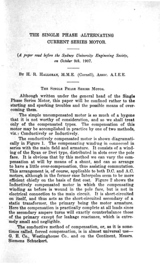
2. /I
fic.1
Flti.Z
A !t._
~
FIIi. tJ Fie. 10
Flc./3
--=--=-...!...-~:;/. '''''~:''::=:: '--=-~
FiD.l6 AHRIIN(;CMCNT J" WIItDlNfi$ lit STATOR SLOTS
0
A
o Fic.4-
Iz
l.J
J,
0
'Fic.8
FII~/d [oil,
F
~
"'~
lUi. 'II rie.lz
1
3. 55
Neglecting for the moment the effect of the short-circuited
armature coils, let us construct the vector diagram of the
motor for a constant current, assuming negligible leakage, and
no iron loss, i.e., for an Ideal Motor. Referring to Figure 3,
let OA represent the direction of the current, and hence also,
that of the field and armature magnetomotive forces. The
armature flux will be zero on account of the compensation, and
that of the field will be in phase with OA, and proportional
to the current-if we neglect the effect of saturation, which
can, however, be taken into account in any special case. Let
this exciting flux be represented by OB. The potential due to
the motor resistance is represented by E10, in phase opposi-
tion to the current. The e.m.f. of self-induction of the field
winding is represented by ~E, in quadrature with the cur-
rent. EsE~ repre~ents the c.e.m.f. of rotation at a certain
speed U. The resultant e.m.f. of the motor is EsO, and calls
for an applied voltage of OEs·
To take into account the effect of the short-circuited
armature coils, let us ·consider the electromotive forces pre-
sent in any such coil at the instant of commutation.
We have here four component voltages as follows :-
E1• . The re-actance voltage of the coil which acts in direct
opposition to any change in current, and is directly propor-
tional to the current.
&. The resistance e.m.f. due to the ohmic resistance of
the coils, leads, and brush contact.
Ea. The speed e.m.f. due to the rotation of the conductors
in the magnetic field.
The above three voltages appear in all commutator
motors, whether they be of the direct or alternating current
type.
In the A.C. we have in addition a transformer e.m.f. E.,
due to the fact that the field flux threading the coil is altern-
ating. To appreciate the effect of this, it should be borne in
mind that the whole field flux threads the coil.
Hence, the . sparking voltage of the motor is the vector
sum of-
E1 +E2 +Ea +E.
With the brushes on the neutral point, as in all motors for
railway work which have to run in both directions, the -value
of Es is obviously zero. Again, since the reactance of the
coils is very small in comparison with their resistance, in-
cluding the leads and brushes, we may safely neglect ~, as
compared with~, and write the sparking voltage as-
= ~ + E.
:a~p.ce it is seep. th&t the cllrrent ip the short-circuited coil is
4. 56
ill. phase with the transformer, e.m.f., so that, as the trans-
former, e.m.f. is in lagging quadrature with the flux producing
it, the current in the short-circuited coils, aud .hence the flux,
due to this current is in laggjng quadrature with the resultant
fl~. -
The e.m.f. due to the self-induction of the coil is in quad-
rature with the current, and if of sufficient size to make the
previous assumption incorrect it may be represented by a
fl~ in phase with the resultant fiux. We have above called
this the reactance e.m.f.
Figure 4 is constructed to take into account the effect
of the short-circuited coil on the diagram, for the same cur-
rent as figure 3.
OA is as" before the current, and OB the exciting flux.
BBI is the fiux' corresponding to the. e.m.f. of self-induc-
tion of the coil.
~B2 is flux due to the transformer e.m.f. in the coil.
ElO is the voltage due to resistance as above. .
~EI is .the voltage induced in the field winding by the
resultant flux, and is composed of the e.m.f. of self-induction
of the field coil E'2Eb corresponding to E zE l in figure 3, and
the e.m.£. due to the flux produced by the short-circuited coil
(BB2), viz. : E2E'2'
E'E2 is the speed e.m.f. due to the field flux OB, and is
the same as EsE2 in figure 3.
EE' is the speed e.m.f. due to the coil fl~ BB2 . !
The subdivision of the voltages EE2 and ~El is purely
arbitrary, and is onlr introduced to show the derivation.
From a comparison of figures 3 and 4, we can draw the
following conclusions :-The r0action of the short-circuited
coil produces:-
1. A displacement of the resultant flux from the current
with an increase or decrease in the absolute value of the flux
-probably increase-depending to a great extent on 1fue
value of the self-induction of the short-circuited coil, the
greater the self-induction, the greater the flux. This is not of
practical value since the self-induction is kept as low as pos-
sible for commutation purposes. The actual effect of the
phase displacement of the current and flux is a decrease in
torque for the same flux. This is obvious from the fundamental
relation :-
Torque = Flux X Component of current.in phase with flux X Const.
2. An increase in power factor.
This is wholly harmful, and is due to the ohmic losses in
the short-circuited coil.
3. An increase in voltage for the same speed or a reduc-
tion in speed at a constant applied voltage.
5. 57
We have assumed complete compensation in the armature
which is never realised in the inductively compensated motor,
although it may even be exceeded in the conductively com-
pensated motor. In any case the effect is very small, but for
th.e sake of completeness it is well to consider its effect. Refer-
ring to figure 5. OA represents the armature ampere turns,
and OB those of the compensating winding. It is noticed that
the compensating ampere turns are not in direct phase oppo-
sition to the armature ampere turns. This is due to the obvious
fact that we cannot have any inductance without appreciable
resistance. Now the voltage induced in the compensating
winding-on open circuit-due to the m.m.f. of the armature
is in lagging quadrature with that m.m.f., and further were
the power factor of that compensating winding zero, the cur-
rent which would flow on the circuit being closed would lag
another quarter pcriod resulting in direat phase opposition.
Due to the resistance the second angle is less than 90 degrees.
Again the windings have some mutual leakage reactance,
so that the most conven'ieht method of introducing the armature
self-induction due to incomplete compensation, is by consider-
ing that only a part of the armature m.:)ll.f. affects the stator
and vice versa. AOh is that part of the armature m.m.f.
which affects the stator, and OBI is that same for the stator
m.m.f.
The vector sum of OA and OB is OC, and induces in the
compensating winding a voltage sufficient to overcome the
resistance of that winding.
Similarly OE is the vector sum of OA and OBu and re-
presents the ampere turns which give rise to the self-induc-
tion of the armature. OE produces in the armature winding
an e.m.f. E10, such as requires an applied e.m.f. to counter-
balance it = OE1.
In figure 6 is given the complete diagram of e.m.f.s. and
fluxes. The only additional vector to figure 4 is the E., E8
which represents t~e e.m.f. required to overcome the armature
self-induction.
The transfor,mer voltage in t he short-circuited coil can be
neutralised when running by a rotation voltage, but when
starting this is impossible, so that other means must be found
to suppress as far as possible the trouble from this cause.
Many methods have been suggested for improving con-
ditions, among which may be mentioned the following :-
1. Reducing the Ampere Turns of the Short-circuited
Coils.-With a given armature and flux density we may reduce
the transformer e.m.f. by increasing the number of poles
keeping the number of armature turns per pole the same, and
also the number of turns per commutator segment the same.
This applies only to lap wound armatures for obvious reasons.
6. 58
In this way the flux cutting the coil is less than before, and
hence also the induced voltage1s less. This method, however,
increases the number of commutator segments, and also in-
creases the total m.m.f. required since it must be the same per
pole as before. 'This n e~itates an increase in copper, or
reduction in efficiency, with accomp{tnying greater rise in
temperature.
Again, if we have more than one turn per commutator
segment, we can incr ease the number of commutator segments
with obvious advantage.
.We may also reduce the length of armature, thus calling
for more turns for the same flux density, voltage, and speed.
This permits of an increase in the munber of commutator seg-
ments.
In all cases we have a practical ~echanical limit to these
alterations since the number of poles and diameter of arma-
ture are generally fixed by other consiuerations, &nd further,
any narrowing down of the armature means a reduction in
cooling surface, and also an increased ohmic resistance since
the proP9rtion of end connection to active conductor becomes
greater. Also, we cannot continue to increase our commutator
indefinitely, because even if space permitted the mechanical
difficulties increase immensely in the construction so that it
becomes a question of cost.
Another method, and one now worked to the limit in all
machines, is to make the &rmature very strong with regard
to the field when we reach a limit due to distortion.
2. The Use of H ard Brushes.-This is a very effective
method as it increases the contact resistance, but we musCallow
only ar educed current density in these brushes, thus re-
quiring a larger commutator with a greater friction loss.
3. The Use of 'Thin Brushes.-We may reduce the thick-
ness of the brush until it covers only' one, or even less than
one commutator segment, thus greatly reducing the period of
short-circuit, but although there is an immense gain, especially
at starting, the brushes are very brittle and liable to break in
service, thus requiring a lot of attention. Furthermore, tiley
require a ·longer commutator, and its attendant evils. A me-
thod of avoiding the lengthening of the commutator is to use
a double' winding, each half complete in itself, and connect-
ing to alternate commutator bars.
The two windings thus work i.n parallel, and the brush is
made thih enough so that no short circuit can occur between
adjacent segments of the same winding. Two brushes are
used separated a short distance on the periphery of the com-
mutator and connected together through a large inductance
which is so wound that it is nOJl-inductive to the main current,
and,highly inductive to the short-circuit current. The obvi9uS
7. <•
59
, ,
effect is to reduce the short circuit current without expen<.~itt1,re
of energy, To prevent sparking on breaking this l:ighl.v inrllC-
~ tive circuit a resistance is shunted across the inductance.
Figure 7 shows the arrangement of brushes on th.e commuta-
tor.
4. Increasing the Reluctance of the Magnetic Path.-This
will cause an increase in the exciting m.m.f., and the com-
parative effect of the short-circuit m.m.f. will to ip.ss. 'fhis
is open to the ohjection that it ,invol res an increase in the
self-induction of the field winding and a consequent reduction
in power .factor. ,
5. Putting a choke'coil in multiple with the field winding.
ing.-This is of little nse, especially if the leakage between the
short-circuited coil and the field is large. Further, it seems
almost impossible to get an economically lower power factor
than that of the field winding. Assuming such a possibility,
the current in the choke coil 011 will lag behind that in the
field coil 012 (figure ~) , and the armature current 018 being
the resultant of these two will lag behind 012, thus coming
more nearly into phase with the resultant flux. This does not
help the sparking, 'but increases the output of the machine.
6. Connecting Resistances Between the Armature Wind-
ing and the Commutator.-This is almost universal. The
effect of these r.esistances is obvious if we consider their
effect on the commutation voltage.
1'he increase in resistance causes a reduction in the effec-
tive short-circuit current: Thus we reduce not only the spark-
ing tendency, but also the reactive effect on the field. It is not
easy, however, to arrange these resistances without unduly
increasing the length of the motor. The most practicable
solution of the difficulty is in placing the resistances in the
armature slots as introduced on the Continent of Europe some
years ago by,Messrs. Ganz and Co., and used with variations
in U.S.A.
In this way it is possible to arrange large enough resist-
ances between the windings and the commutator to ensnre
satisfactory starting.
But here we, of course, sacrifice efficiency. · Further, the
windings take up slot space and increase the armature losses,
and hence temperature rise in the armature, giving only the
one advantage of increased resistance of short-circuit. Again,
for the same amount of active armatUl'e copper the insertion
of the ,resistances means an increase in depth of slot, and lmless
placed themselves at the bottom of the slot increase, the react-
ance of the main winding and thus in some measure counter-
act their own beneficial effect. As regards their own react-
ance, they are, when employed, straight and wound doubled
back on themselves, thus having no reactance. The method
8. sO
employed by the W estinghouse Co. is to place the resistance
connections in separate slots below the main armature slots as
indjcated in plllching shown in figure 9. In small sizes of
machines in which the current carrying capacity of the resist-
ances has not to be very large~e firm of Siemens-Schuckert,
employ strip resistances. OWIng to the limited length of strip
we must run the current densities very high, .and a perforated
strip is used to increase the radiating surface without increas-
ing the effective conductor cross-section. •
In larg~ sizes it is impossible to get sufficient carrying
capacity and resistance in these strips, and the above company
reverts to the practice of placing the resistances in the slots.
They have just brought out a new arrangement, a descrip-
tion of which appeared in the" Elektrotechnische Zeitschrift,"
about August, 1906, and although the claims of a 15 per cent.
increase in output, and 3 per cent. increase in efficiency, may
be realised over the plain resistance in the main armature
slots, it is hard to see where the method can compare with·
the Lamme method used by the Westinghouse Qo~pany.
RUNNING CONDI'l 'IONS.
It was mentioned above that the conditions could be more
easily improved while running than at rest, due to the .pos-
sibility of neutralising the transformer voltage. Could the
transformer voltage be neutralised by an opposing 'Voltage, then
one would obtain not only favourable conditions for spark-
less running, but also one could build an armature for a
smaller effective current-due to absence of short-circuit----:and
thus reduce the size of commutator. It is obvious at a glance
that it is impossible to neutralise the transformer voltage with
an induced voltage in the opposite direction, since wheil the
resultant e.m.f. falls to zero, so also must the turning moment.
The only course open is to neutralise the transformer e.m.f.
by an e.m.f., induced by rotation of the armature in a. cross
field. 'The mechanical position of the field will be in the centre
between the main field poles, and so any flux there will not
affect the main filled flux in value.
. The required. e.m.f. must be produced by a flux whose
time phase is one quarter period ahead of the main field flux
-as is the ease in repulsion motors.
As . any methods applicable to conductively compensated
motors are also applicable to Conductively compensated motors,
a discussion of the latter will include the former.
In the conductively compensated motor, the armature and
field and compensating winding all carry the sa~e current, r.
The m.m.f. Ml of the armature and that M2 of the compen-
sating winding act in opposition to one. another, so that the
9. 61
resultant m.m.f. Ms is 180 degrees out of phase with the cur-
. rent 1. "'vVe, of course, assume that the compensation will be
enough, or more than enough, in which case only we have the
resultant Ms· In order, however, to neutrailse the transformer
e.m.f. by an e.m.f. due to rotation, it is necessary to produce
a flux which is 90 degrees ahead of the phase of the excitation
current. In o~der to neutralise the reactance voltltge, we need
a voltage sucli as would be produced by Ms· . Hence, in order
to neutralise both of these two voltages, the flux in the neutral
zone must be at an agnle between 90 degrees and 180 degrees,
.according to which is the greater, with the excitation current.
A resultant m.m.f. of this nature is obtained if one allow
either the eurrent 12 to lag behind the current 11 as in figures
10 and 11 or the phase of the armature current 11 ·to be in
advance of the motor current I'll as in figures 12 and 13.
The first case will occur when an inductionless resistance
is connected in parallel with the compensation winding figure
11. The current in lthe compensated winding will then lag
90 degrees behind that in the resistance, and their resultant
flows through the armature and the field winding.
The magnitude and phase position of the resultant m.m.f.
can, by suitably proportionnig the parrallel resistance, and
the numbJlr of windings · of the compensating coils, be so ar-
ranged that the rmlultant m.m.f. of the armature coils be-
comes zero.
The second case will occur when a choking coil is con-
nected in parallel with the armature figure 13. Neglecting
the armature reactance, the armature current when running
will be in phase with the armature voltage, but the current
of the choke coil will lag 90 degrees behind. Their sum will
flow through the field and compensating winding. Here also
we can jl.djust the phase position and magnitude of Ms to
suit.
If one wishes to avoid regulation of the choking coil, the
connections shown in Figure 11 have the advantage that the
resultant m.m.f. is directly proportional to the armature cur-
rent-but only when the field is unsaturated is the transformer
voltage proportional to the armature current.
Against this arrangement we must count a reduced
efficiency.
Against that of figure 13 we must count a lower power
factor and a higher speed due to the phase difference in flux
• and current. Neither of the above arrangements are very
satisfactory on account of the complicated regulation re-
quired. .
The latest method of Messrs. Siemens-Schuckert is to neu-
tralise the reactance voJtage by an interpole Winding, as com-
monly done on direct clrrent machinery, and to neutralise
10. 62
the transformer voltage by 'a speed voltage induced by a flux
which is supplied by a winding arranged in shunt either with
the armature or the whole machine.
The diagrammatic arrangftment of windings and vector
diagram for the same are sllown in figures 14 and 15, while
figures 16 and 17 show the method of arranging them in the
stator slots.
In the vector diagram-
OI represents the direction of motor current
Ef is the voltage dl'op due to field inductance.
Er is the voltllige drop due to motor resistance.
E is the e.m.f. induced in the armature by its
rotation at a speed U.
This gives a total voltage at motor terminals of Et ,
The m.m.f. of the shunt winding is shown by M-shunt, in
quadrature, with the voltage Et , the winding being so arranged
that the m.m.f. leads the terminal voltage.
'The m.m.f. of the interpole winding is shown by M-series,
its change in direction being obtained by reversal of the wind-
ing.
The resultant of these two is shown by M, which is the
flux due to the composite excitation of the auxili&ry pole.
In figure 16 that part of the compensation winding whose
m.m.f. is completely neutralised by that of the armature is
shown by the large cirlces, and that part which is used for
compensating the reactance voltage of the short-circuited coil
-shown in the diagram figure 14, as the series coil-is indi-
cated by the small circles. The direction of currents is shown
by the familiar convention of dots and crosses.
It will be noticed that in the slots, a. a.,.the m.m.f. of the
series coil opposes that of the compensation winding, and in
the others assists. _ It would obviously be better to omit the
opposing coils and reduce the turns of the compensation wind-
ing correspondingly, in a similar manner the 8ther coils could
be included in the compensation winding.
In the slots where we omit the opposing coils we also have
the slnmt winding--which is shown by the finer lines and
circles~so that we may use the space thus made available for
the shlmt winding.
In jigure 16 the dotted lines indicate the direction of the
series, and shunt fluxes, and from a study of the same it is •
obvious that the arrangement there shown obviates any mutual
inductive effects.
As the strength of 1he shunt excitation required depends
QP th(;l.cllrrent talren by- the motorl it -is obyiolls th~t tQ obtf!,m
11. 63
complete compensation at all loads we must regulate the shunt
field. This is done with a variable inductance in series with
it.
Since the current in the shunt coil should-for the best
effect-be in quadrature with the current.in the armature, it is
generally found advisable to connect the shunt field across the
armature instead of the motor as shown in figure 14. This
is'due to ihe fact that the armature voltage and current are
nearly in phase due to compensation.
P. N.RuSSELL
SCHOOL
OF
ENGIN EERING
W. H. WARREN
COLLECTION