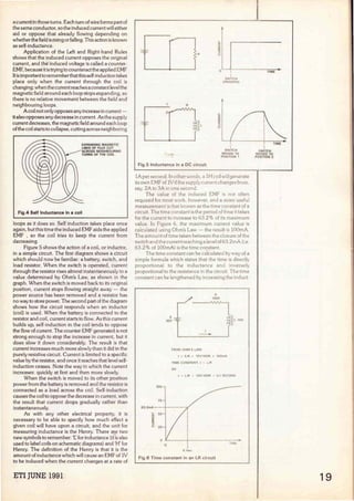
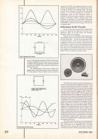
1) An inductor opposes changes in current through self-induction, generating a counter-EMF when current increases or decreases. This causes the current in an AC inductive circuit to lag 90 degrees behind the voltage.
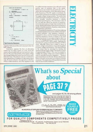
2) Inductive reactance represents an inductor's opposition to AC current, and increases with frequency and inductance. It can be calculated using XL=2πfL.
3) A purely inductive AC circuit does not consume any power on average, as energy stored in the magnetic field during one half of the cycle is returned during the other half.
Model Call Girl in Narela Delhi reach out to us at 🔝8264348440🔝
BACK to BASIC 5.pdf
1. 5
This month Paul
Coxwell examines the
concept oíInductance
18
RackToBasics
----......-----
Fig.1 The magnetic field around a coil
A
t this point in the series you should have
a good knowledge of basic electrical
circuits. Back in part 2 we examined the
link between magnetism and electricity,
and saw that a magnetic field is gener-
ated around a current-carrying conductor. The
existence of this field can be proven by placing a small
compass next to the conductor. The electromagnet
is a device which puts this field to good use. If a wire
is wound into a coil, the magnetic field surrounding
each turn of the conductor combines with those next
to it. This results in a much stronger magnetic field
surrounding the coil (Figure. 1).
The magnetic field may be strengthened by
increasing the current flowing through the coil or by
adding extra turns to the coil. The amount of magnetic
power available is called the magneto-motive force
(MMF) and is measured in ampere-turns. For
example, if a current of 2A is passed through a 10-turn
coil of wire, the MMF is 20 ampere-turns. The same
MMF could also be obtained by passing lA through
a 10-turn coil, or 0.5A through a 40-turn coil. Air is
(l
CDRE---..
COIL
ARROWS INDICATE THE MOVEMENT Of
ARMATURE WHEN RELAY IS ENERGISED
Fig.2 The Relay
not one of the best conductors of magnetic lines of
flux, and practical electromagnets are wound with a
soft iron core. This core concentrates the magnetic
field and the resulting electromagnet can be used in
a variety of applications. One application is that of the
relay (Figure 2) . A relay can be thought of as a remote
switch;jnstead of a small lever being used to open or
close the switch contacts, an electromagnet is
employed instead. When a current is passed through
the coil it generates a magnetic field. This field causes
the relay's armature to be pulled clown, thus activating
the contacts.
Relays are available in many different sizes, from
miniature types intended for remote-control of models
right up to industrial power relays that are capable of
switching very powerful equipment on and off. The
relay allows current flow in one circuit to control
another, without there being any direct electrical
connection between the two. lt is, for instance, a
common requirement to be able to remotely control
a very large electric motor. The cables that supply
power to the motor may need to be very thick in order
to carry the high current; to run such cables over
severa! hundred yards would be impractical, not to
mention very expensive.If a relay is fitted at the motor
site, however, much lighter wires can be used to
connect to the relay' s coil to provide remote control.
Figure 3 shows another way in which electromagnets
Fig.3 The Electric Bell
are used: a common electric bell. Notice that the bell
also has a pair of contacts, just like the relay, only this
time they form part of the circuit to the coils
themselves. When power is applied, the coils generate
a magnetic field which attracts the armature, causing
it to strike the bell gong. At the same time, the
movement of the armature has opened the switch
contacts, thus removing power to the coils. A spring
returns the armature to its former position, which
doses the contacts and applies power to the coils once
again. The whole process is repeated several times a
second, with the result that the gong is repeatedly hit
to produce a continuous ringing sound.
The relay and the electric bell are just two
examples of the way in which a coil may be used to
control externa! events by way of the generated
magnetic field. There is another important aspect of
the coil, however, in that it can influence the circuit
of which it forms a part. This property is called
inductance.
lnductance
Recall that when a conductor is moved across a
magnetic field (or vice versa), a current is induced.
This is the converse relationship to a current causing
a magnetic field to be generated. Thinking carefully
about the construction of a coil (Figure 4) , as current
through the coil increases, a magnetic field is formed
around each loop of the coil. As this field expands,
it cuts across neighboring turns of the coi!, and induces
ETI JUNE 1991
2. a current in those turns. Each turn of wire forms part of
the same conductor, so the induced current will either
aid or oppose that already flowing depending on
whether the field is rising orfalling. This action is known
as self-inductance.
Application of the Left and Right-hand Rules
shows that the induced current opposes the original
current, and the induced voltage is called a counter-
EMF, because it istryingto counteractthe applied EMF
lt is importantto rememberthatthis self-induction takes
place only when the current through the coi! is
changing;when the currentreaches a constantleve1the
magnetic field around each loop stops expanding, so
there is no relative movement between the field and
neighbouring loops.
A coi! not only opposes any increase in current -
italso opposes any decrease in current. As the supply
currentdecreases, the magneticfield around each loop
ofthe coi!startsto collapse, cutting across neighboring
EXPAlllOING MAGNETIC
LllllES OF FLUX CUT
ACROSS lllEJGHBOURING
TURlllS Of THE COIL
Fig.4 Self lnductance in a coil
loops as it does so. Self induction takes place once
again, but this time the induced EMF aids the applied
EMF , so the coi! tries to keep the current from
decreasing.
Figure 5 shows the action of a coi!, or inductor,
in a simple circuit. The first diagram shows a circuit
which should now be familiar: a battery, switch, and
load resistor. When the switch is operated, current
through the resistor rises almost instantaneously to a
value determined by Ohm's Law, as shown in the
graph. When the switch is moved back to its original
position, current stops flowing straight away - the
power source has been removed and a resistor has
no way to store power. The second part of the diagram
shows how the circuit responds when an inductor
(coi!) is used. When the battery is connected to the
resistor and coi!, current starts to flow. As this current
builds up, self-induction in the coi! tends to oppose
the flow of current. The counter-EMF generated is not
strong enough to stop the increase in current, but it
does slow it clown considerably. The result is that
current increases much more slowly than it did in the
purely resistive circuit. Current is limited to a specifíc
value by the resistor, and once it reaches that leve! self-
induction ceases. Note the way in which the current
increases: quickly at first and then more slowly.
When the switch is moved to its other position
power from the battery is removed and the resistor is
connected as a load across the coi!. Self-induction
causes the coil to oppose the decrease in current, with
the result that current drops gradually rather than
instantaneously.
As with any other electrical property, it is
necessary to be able to specify how much effect a
given coil will have upon a circuit, and the unit for
measuring inductance is the Henry. There are two
new symbols to remember: 'l.'. for inductance (it is also
used to label coils on schematic diagrams) and 'H' for
Henry. The definition of the Henry is that it is the
amount of inductance which will cause an EMF of lV
to be induced when the current changes at a rate of
ETI JUNE 1991
R
R
1
n
Fig.5 lnductance in a OC circuit
o 1
1
SWITCH
OPEAATEO
1
SWITCH
MOVED TO
POSITION 1
lA persecond. ln other words, a lH coil will generate
its own EMF of lVifthe supply current changes from,
say, ZA to 3A in one second.
The value of the induced EMF is not often
required for most work, however, anda more useful
measurement is that known as the time constan! of a
circuit. The time constan! is the period of time it takes
for the current to increase to 63.2% of its maximum
value. In Figure 6, the maximum current value is
calculated using Ohm's Law - the result is lOOmA.
The amount of time taken between the closure of the
switch and the currentreaching a leve! of63.ZmA (i e
63.2% of lOOmA) is the time constant.
The time constant can be calculated by way of a
simple formula which states that the time is directly
proportional to the inductance and inversely
proportional to the resistance in the circuit The time
constant can be lengthened by increasing the induct-
100
75
63 2roA--
,_ 50
~
a:
:>
u 25
o
.l
10V --=--
1
-
FROM OHM'S LAW:
R
100R
1 = E/R = 10V/100R = 100mA
TIME CONSTANT. t = L/R
so
11 L lOli
t = L/R = 10H/100A = O1 SECOND
Fig.6 Time constant in an LR circuit
TIME
SWITCH
MOVED TO
POSITION 2
19
3. 20
+16
p
-10 ~~-,-~~-.-~~.....-~-..~~-.-~---,.....-~-..~--.
o 46 90 135 180 226 270 315 360
DEGREES
1
-
·O·
CURRENT AND VOLTAGE
IN PHASE
Fig.7 Resistive AC circuit
... 10 so•
p
anee or reducing the resistance. Notice that the time
constant is affected by the entire circuit, not just the
coi! itself. In the circuit shown, the current through the
coi! will reach 63.2% of its maximum value in one-
tenth of a second.
The measurement of the time constant also
applies when current through the coil is decreasing.
lt is the period of time it takes for the curren! to
CURRENT LAGS VOLTAGE BY 90°
VOLTAGE LEADS CURRENT BY 90°
AVERAGE POWER ~ O
- IOL-~--,..~~-.-~~r-~--,..~~-.-~~r-~-,-~--,
O 45 90 135 180 225 Z70 315 380
DEGREES
Fig.8 lnductive AC circuit
diminish by 63.2% of its original value (or, to put it
another way, the length of time it takes for the current
to drop to 36.8% of its starting value). We have
covered sorne importan! concepts in the preceding
section, so it is worth pausing for a moment to
recapitulate. Here are the importan! points to
remember: Inductance always opposes a change in
curren!; increasing supply curren! causes self-
induction to generate a counter-EMF; decreasing
su¡:íply curren! causes self-induction to generate an
aiding EMF; an inductor stores energy in the form of
a magnetic field.
lnductance In AC Circuits
So far we have seen how inductance affects OC
circuits by delaying the build-up of curren! to its
maximum value. In an AC circuí!, the situation
becomes a little more complex.
Figure 7 shows a simple AC circuí! consisting of
just one load resistor anda power source. The graph
should look familiar - it is the one we used last month
to examine power in AC circuits. Notice how the
voltage and curren! curves, E and 1, are in phase with
each other (i.e. they both reach their positive peak at
the same time, both cross the zero point at the same
time, and so on) . Recall that the power curve never
goes negative, because the product of two negative
values (E and 1) is always a positive value.
In Figure 8 the resistor has been replaced by an
inductor. Look closely at the voltage and curren!curves
and you will see thatthey are 90° out of phase - as E
reaches its negative peak,for instance, 1is just crossing
zero on its way to the negative peak. We can say either
that the curren! lags the voltage by 90° or that the
voltage leads the curren! by 90°.The descriptions are
equivalen! and are justtwo different ways ofsayingthe
same thing. The reason for this phase shift is the self-
inductance ofthe coil. The phase ofthe source voltage
is determined by the power supply, but the inductor
causes the current to lag behind. The graph in Figure
8 also shows how the power curve would appear.
When voltage and curren! are both positive or both
negative, the resulting product (P) is positive. When
either E or 1is positive and the other is negative, the
power curve drops below zero. As has been already
stated, a negative power levelimplies that the circuí! is
supplying power instead of consuming it. During the
positive parts ofthe powercyclethe inductoriscreating
an expanding magnetic field. During the negative
portions, the magnetic field is collapsing and returning
its energy to the circuí!.
You will see that the power curve is symmetrical
and centered on zero, so its average level is, therefore,
zero. This leads to an importan! fact: A purely
inductive circuit, such as the one shown, does no!
consume any power. Ali the power taken to create a
ETI JUNE 1991
4. OHM'S LAW FOR REACTANCE:
1 = E/X THEREFORE E = IX ANO X = E/I
X = REACTANCE
XL = INDUCTIVE REACTANCE
XL = 2rrfL
WHERE L = INDUCTANCE. f = FREQUENCY
EXAMPLE:
XL = 2nfl
1
-
= 2 X 3.14 X 60 X 2
=~
XL =?
l = ,
L 2H
1 = E/XL = 120V/753 6R = 159mA
Fig.9 lnductive Reactance
magnetic field around the coi! is returned when the
field collapses.
Inductance opposes the flow of alternating
current but not direct current. In a DC circuit the
current will eventually build up to its maximum value,
but in an AC circuit the polarity of the supply voltage
has changed before the curren! has had time to reach
that same leve!. The inductor may be considered to
have a special kind of 'resistance' to alternating current
only. To avoid confusion, this opposition to the flow
of AC is called reactance, and when applied to coils
it is called inductive reactance (you will come across
another type of reactance Jater in this series).
Reactance is not constan! for any particular coi! - it
varíes with the frequency of the alternating current.
lf the frequency of the AC supply is increased, the
curren! does not have as much time to increase before
the supply voltage changes polarity. The result is that
current decreases as frequency increases, orto put it
more formally, inductive reactance is directly
proportional to frequency. The inductance value of
the coi! itself also affects the amount of reactance;
more inductance gives a longer time constan! for the
circuit, thereby preventing curren! from increasing so
rapidly. lnductive reactance, therefore, is also directly
proportional to inductance.
The symbolfor reactance is 'X' and when referring
to inductivereactance itis usual to addthe subscript 'l.:
to avoid confusion. Like resistance, reactance is
measured in ohms, and the formula for calculating
inductive reactance is shown in Figure 9. For most
practica) purposes it is accurate enough to take rr as
3.14. The example shows a 2H inductor connected
directly across'"a 120V 60Hz supply. Applying the
formula for XL gives an inductive reactance of 753.6
ohms. Although Ohm's Law is stated in terms of
curren!, voltage, and resistance, it may also be applied
to current, voltage, and reactance. The curren!flowing
in the circuit may be calculated by dividing the
reactance into the supply voltage. The result is a curren!
of approximately 159mA. One may be tempted to
multiply the supply voltage and current together in
order to calculate the power dissipation - doing so
gives aresult ofjusiover 19 watts. We have alreadyseen
that an inductive circuit does not in theory consume
any power. The explanation ofthis problem forms the
basis of next month's installment.
and pages 45, 55, 58 among others
Simply that these are sorne of the pages whlch show how
exceptionally wide and varled are the ranges of
COMPONENTS, PRODUCTSand MATERIALStobefound
in our 1991 Catalogue. Much practica! information is
included and it's ali well presented, illustrated and easy to
look up - and to order from.
WE ARE SPECIALIST SUPPLIERS FOR SIEMENS FINEQUALITY COMPONENTS
Please send f1SO (cash/P.O.loheque/stamps) for your
1991 EV catalogue (postage paid In UK) We give you a
refund voucherfor f1.50 usable towards your next order
for E:5.00 or more.
FOR QUALITY COMPONENTS COMPETITIVELY PRICED
Catalogue orders to:-
ELECTROVALUE LTD, 28a ST. Jude's Ad., Englefield Green, Egham, SurreyTW20 OHB
Phone: 0784 433 603 Fax: 0784 435 216
ETI JUNE 1991 21