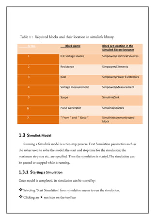
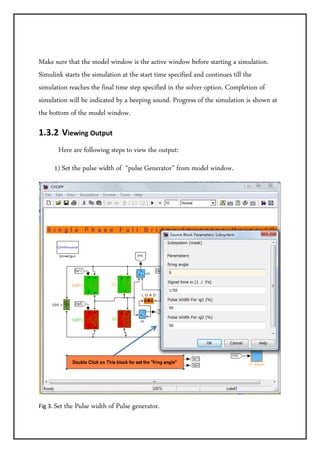
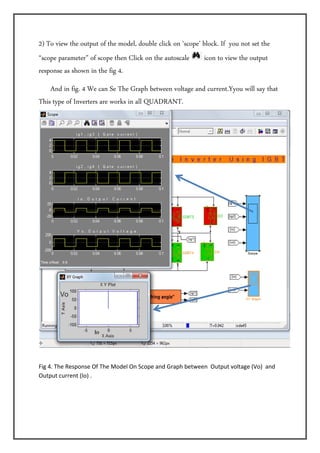
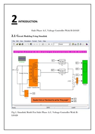
Downloaded 467 times
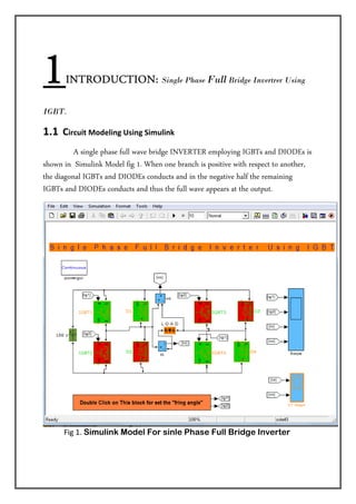

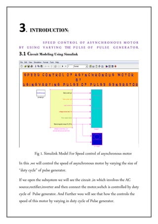
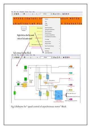
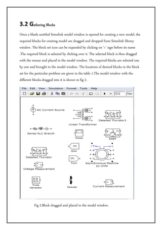


The document describes simulations of various power electronic circuits using Simulink. It includes simulations of a single-phase full bridge inverter using IGBTs, an AC voltage controller with an R-load using thyristors, and speed control of an asynchronous motor by varying the pulse of a pulse generator. The key steps are modeling the circuits in Simulink, selecting the required blocks from the library, setting simulation parameters, and viewing the output on scopes to analyze the performance of the circuits.


![Getting Started with Apache Spark: Big Data Made Simple [Free Meetup]](https://cdn.slidesharecdn.com/ss_thumbnails/apachesparkgettingstarted-260203175547-8361bcc3-thumbnail.jpg?width=640&height=640&fit=bounds)


