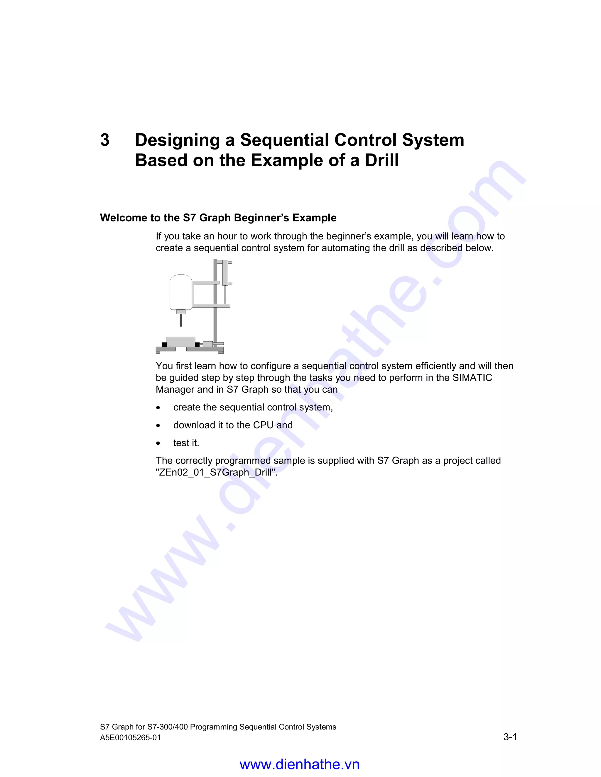
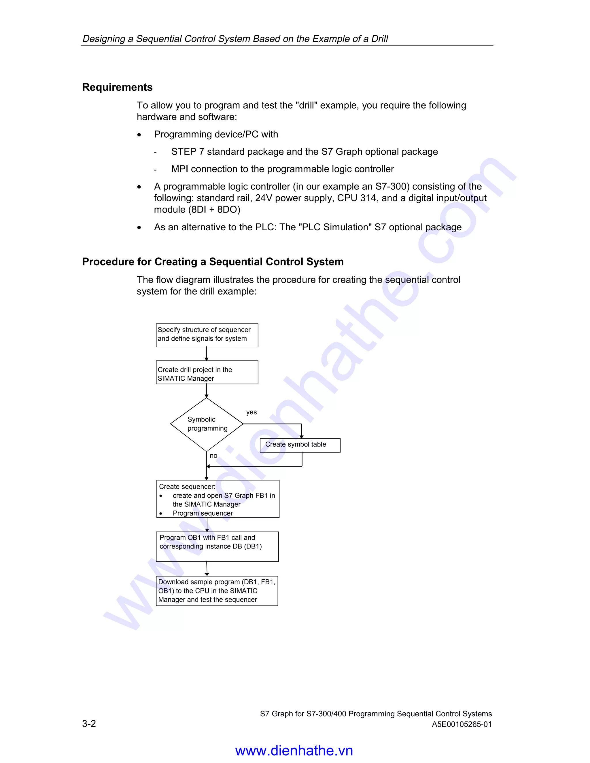
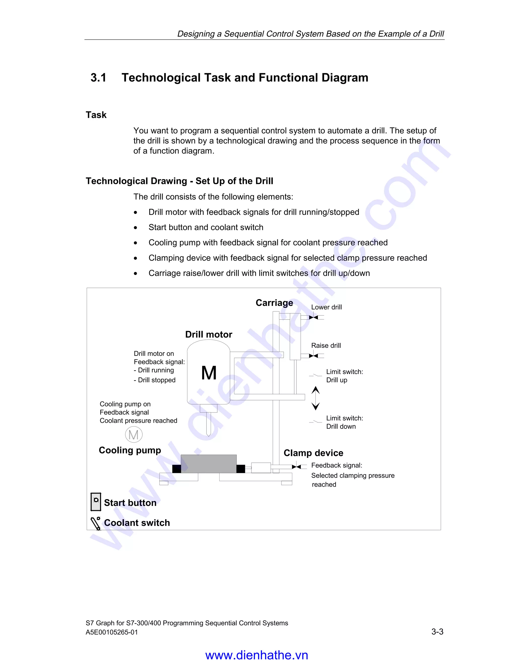
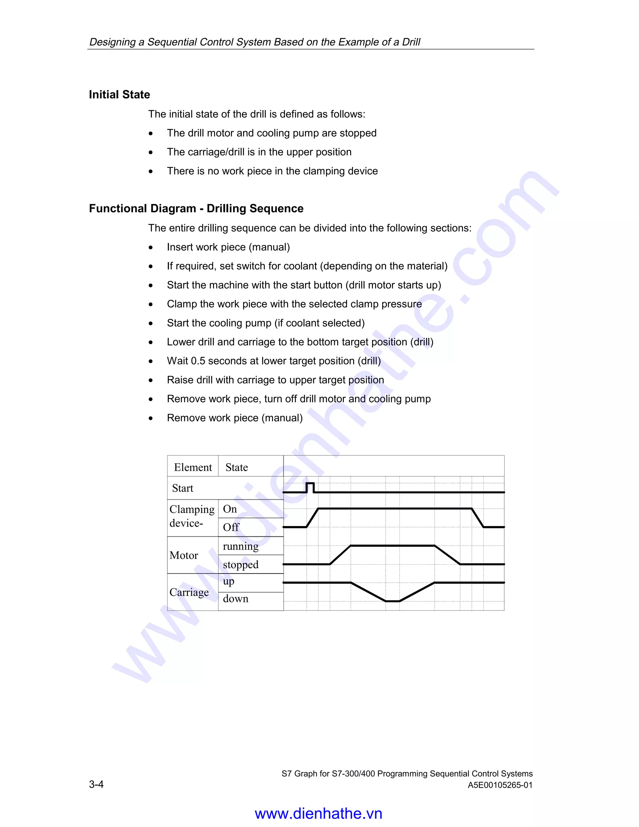
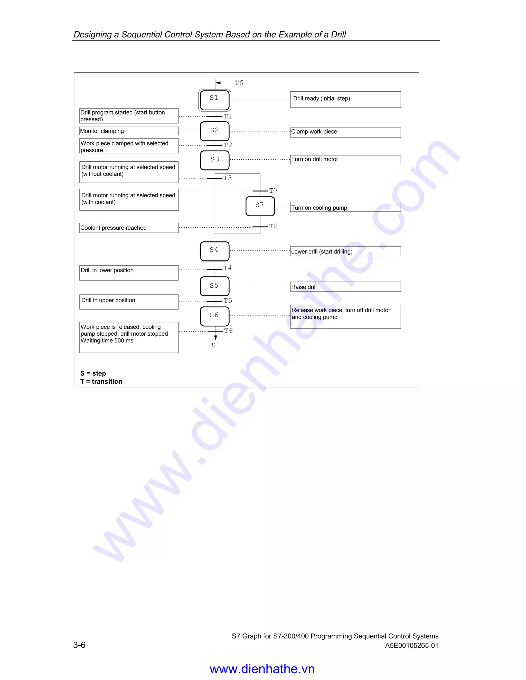
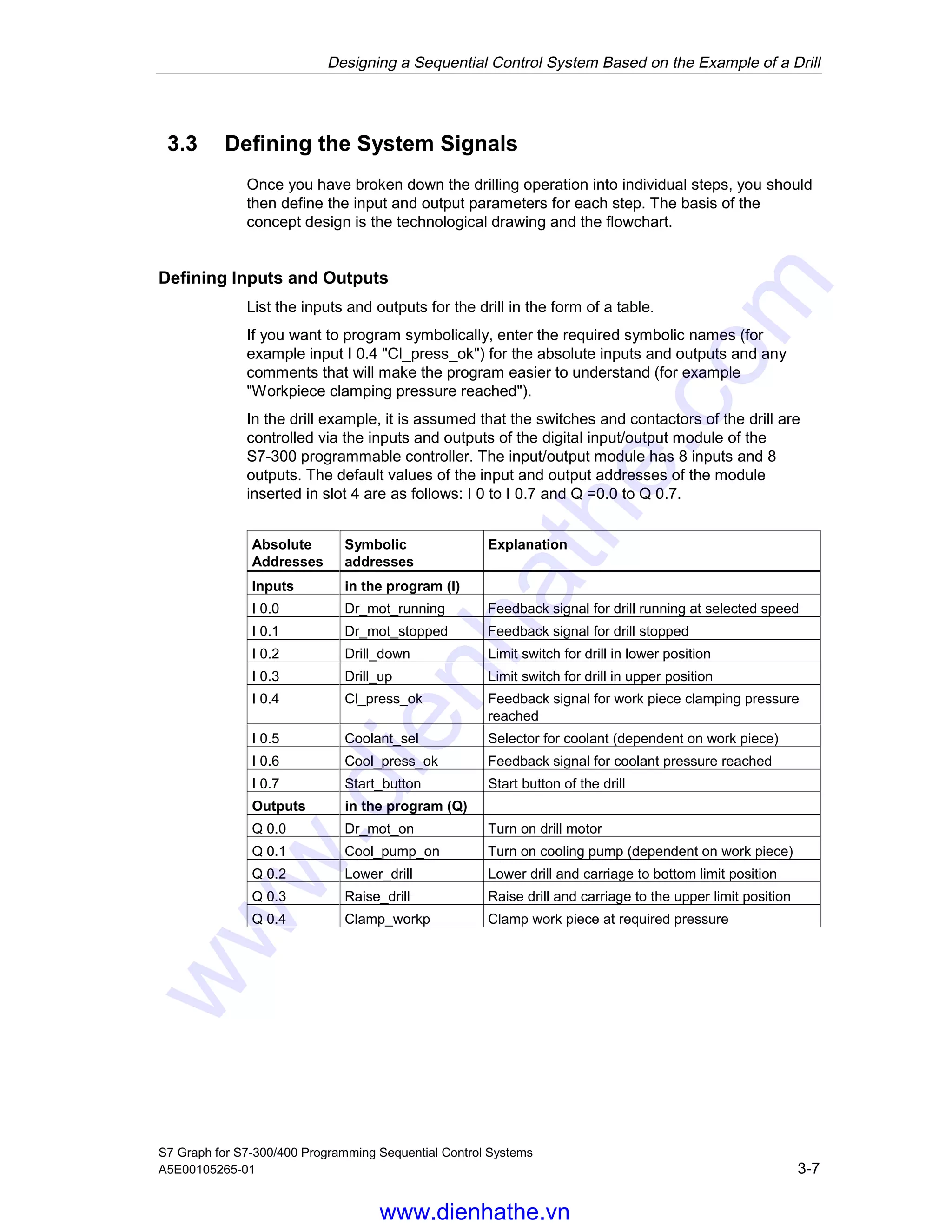
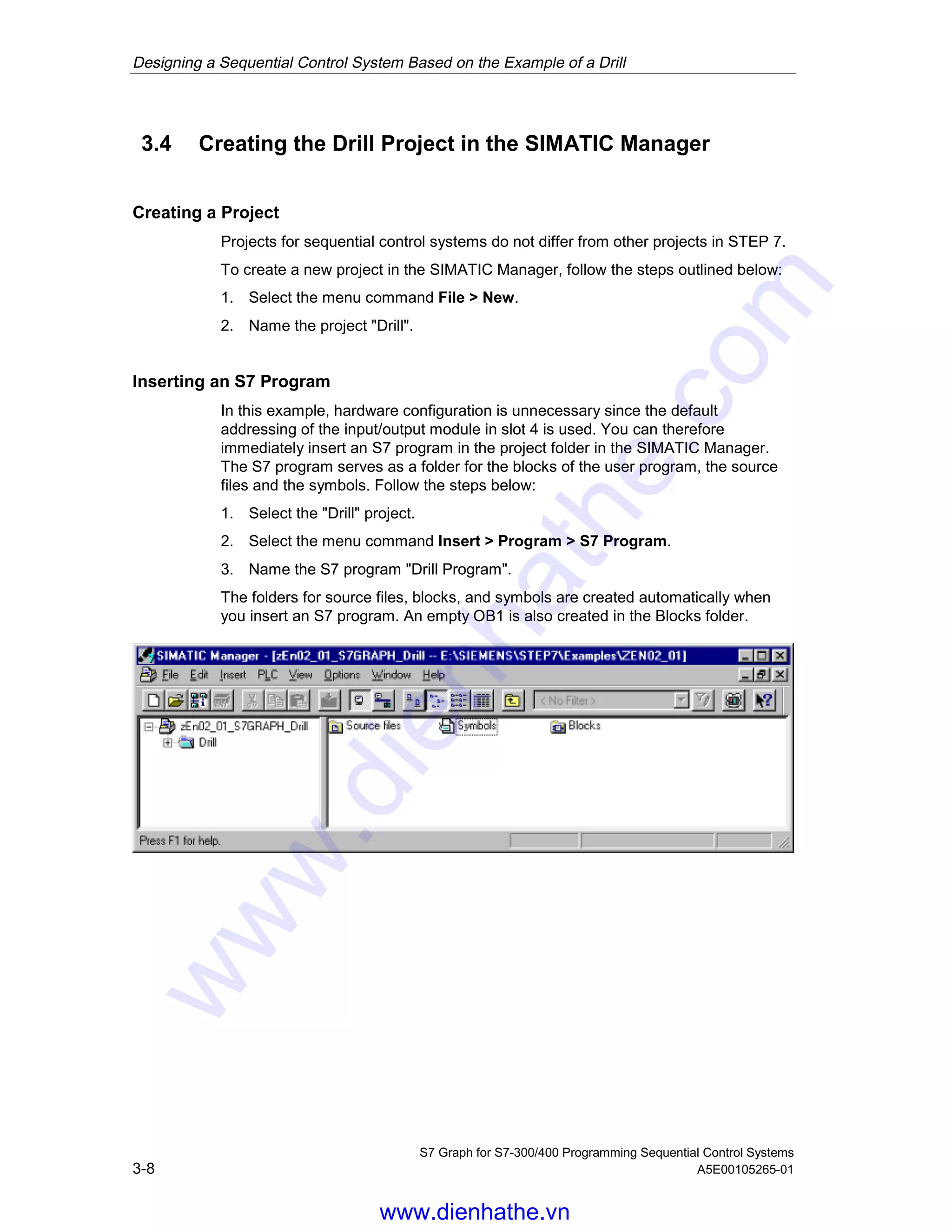
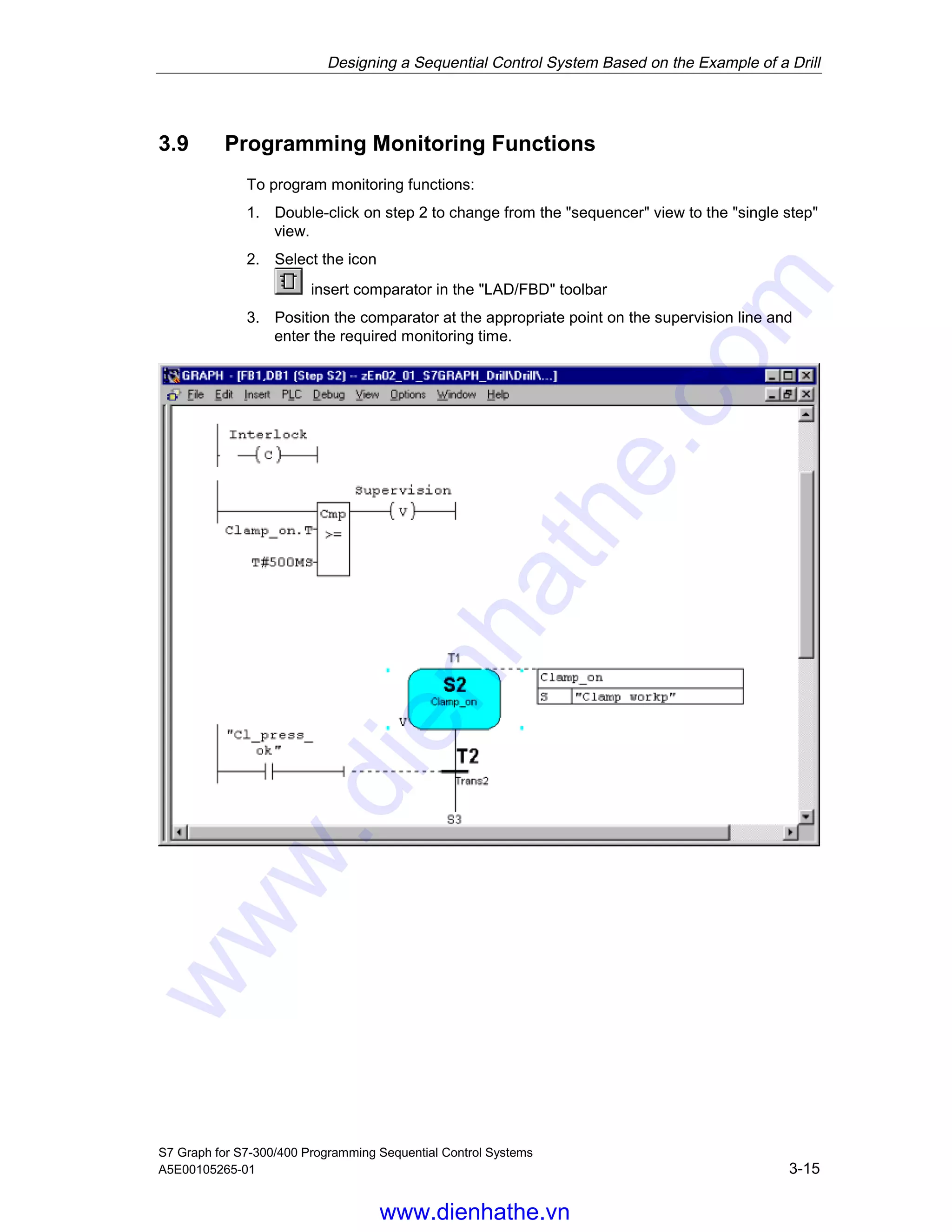
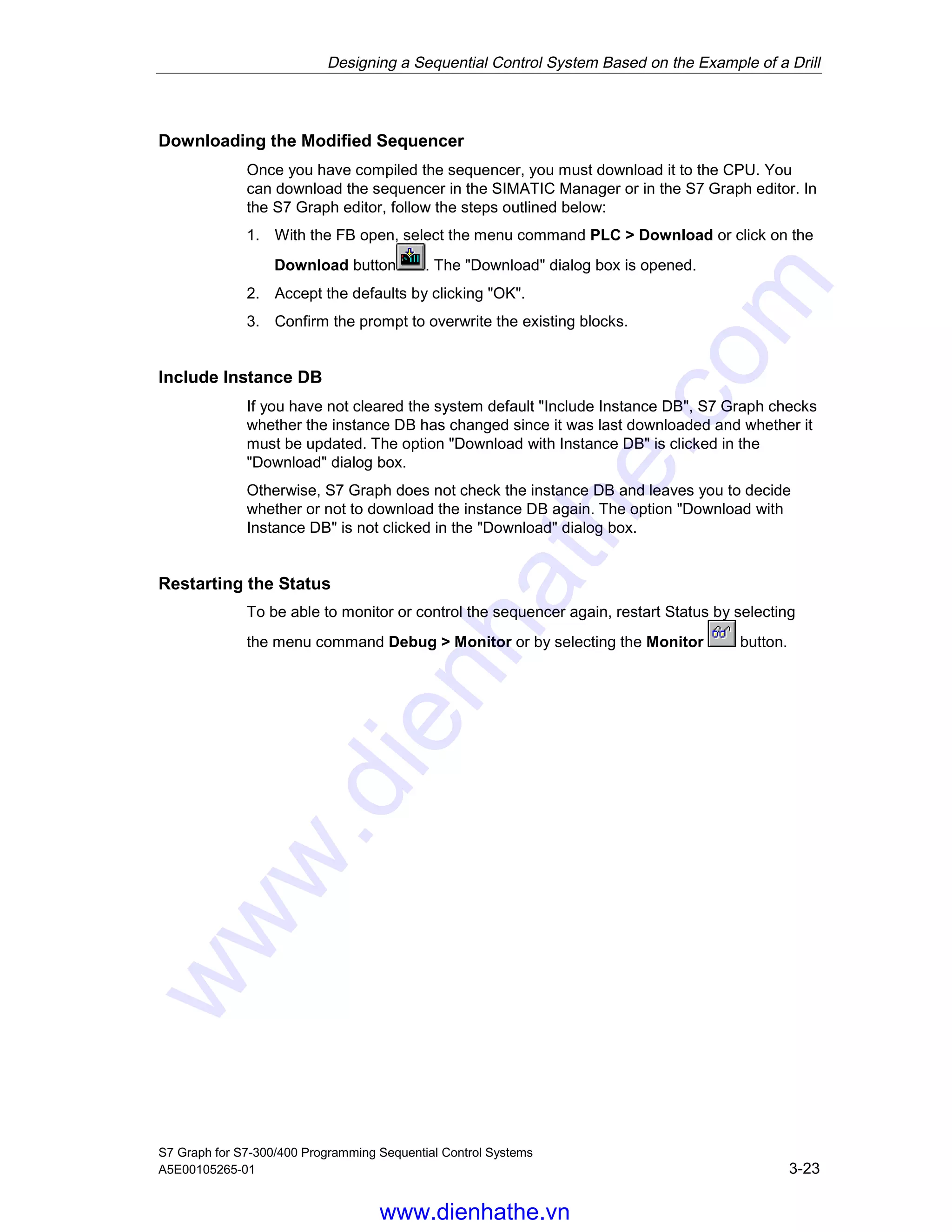
Siemens,
Catalog Thiết Bị Tự Động Siemens, Catalog Thiết Bị Tự Động
Catalog Phụ Kiện Siemens, Catalog Phụ Kiện,
Catalog Siemens, Catalog,
https://www.dienhathe.com,
Chi tiết các sản phẩm khác của Siemens tại https://dienhathe.com
Xem thêm các Catalog khác của Siemens tại https://dienhathe.info
Để nhận báo giá sản phẩm Siemens vui lòng gọi: 0907.764.966
1) The document is a daily summary of posts from an industrial automation forum hosted on Control.com.
2) It includes questions and responses on topics like wiring a limit switch to control a fan, troubleshooting high vibration readings on a gas turbine, and replacing relay logic with a single chip controller.
3) Recommendations provided in the responses include checking valve positions and limit switches, reviewing maintenance records for clues on vibration increases, and considering programmable logic controllers or microcontrollers as replacements for relay logic systems.
This Siemens plc programming example PDF 2 is an expansion the counter PDF example 1.and has counter structured text programming example. Also a supporting video and more programming samples can be found at http://bin95.com/Siemens-Training/siemens-plc-programming-examples.htm
This 3-page technical manual provides an introductory guide to programming Omron PLCs. It discusses Omron addressing schemes for inputs, outputs, memory, timers, counters, and more. It also describes common ladder programming blocks like timers, counters, jumps, and subroutines. Finally, it explains how to interface an Omron PLC with SCADA software by setting up I/O drivers and defining tags for monitoring inputs/outputs and controlling the PLC. The document was prepared in March 2012 by Sanjay AJ for educational purposes.
A few sample slides from a PowerPoint our instructor made of a NY on-site PLC Training class. Our customers receive the full slides with instructor’s notes, tips and references.
This document provides information about the G7F-ADHA A/D-D/A module for use with GM7 and MASTER-K80S PLCs. It can convert analog inputs like voltage and current to 12-bit digital values, and convert digital values to analog outputs. Specifications and characteristics of the analog input and output are provided. Examples show how to control an inverter's frequency using 0-10VDC or 4-20mA control signals from the module. Wiring diagrams, programming examples, and attached documents are included to help interface the module with an inverter. Frequently asked questions about the module and interfacing with an inverter are also listed.
This document provides an introduction to PID controllers and PLC systems. It discusses the basic components and functions of PID controllers, including proportional, integral and derivative controls. It also summarizes the basic architecture of PLC systems, including the CPU, memory, input/output units and programming methods like ladder logic, statement lists and function block diagrams. Common instructions for timers, counters and logic operations are also covered.
The document introduces ladder diagrams and their basic components and logic. Ladder diagrams are a graphical programming language used to program programmable logic controllers (PLCs). Each rung represents a program statement with inputs on the left and outputs on the right. The PLC executes the ladder diagram by reading input states and determining output states from top to bottom. The document also describes common logic components like contacts, coils, timers, and counters used in ladder diagrams.
The document discusses various programmable peripheral interface chips used for input/output interfacing in microprocessor systems. It describes the architecture and operating modes of the 8255 Programmable Peripheral Interface chip, which has three 8-bit I/O ports that can be programmed for applications like keyboard interfacing, LED displays, analog-to-digital conversion, digital-to-analog conversion, temperature control, stepper motor control, and traffic light control systems. Circuit diagrams and software flowcharts are provided for different interfacing applications using the 8255 PPI chip.
These slides and attached demo video compliment our Complete Video DVD on the topic mater. To see the AB Cables – Drivers DVD, click http://www.bin95.com/Industrial-Training-Videos/AB-PLC-Cables-Drivers.htm
Also see http://www.bin95.com/Industrial-Training-Videos/plc_training_videos.htm for a complete 10 DVD PLC Course.
The document describes the design of an arithmetic logic unit (ALU) for an embedded system as a final project. Key details include:
1. The ALU is designed with a 5-stage pipeline and performs operations like addition, subtraction, logical operations, and multiplication on 16-bit operands from registers.
2. It includes modules for basic logic functions like AND, OR, XOR, and NOT as well as a carry look-ahead adder and multiplier.
3. The project is implemented in Verilog HDL with modules, registers, and always blocks to control the flow through each pipeline stage on each clock cycle.
speed control of induction motor using plc and vfdmanishrair
This document discusses speed control of an induction motor using a PLC. It describes the main components involved, including a variable frequency drive, switched mode power supply, and PLC. It also provides information on ladder logic programming and the basic signal flow within a PLC system from sensor inputs to motor outputs.
Digital inputs and outputs can be controlled through various logic priorities. The highest priority is direct control, followed by demand, timer, and time-of-use controls. Outputs default to an always-on state, and the control logics determine when to turn them off. Inputs can be configured for different functions like event monitoring, pulse counting, or interfacing with energy meters. Both inputs and outputs can be inverted, filtered, or controlled through timers and other functions.
The document discusses the 8155 Programmable Peripheral Interface chip. It can be used as an interface between a microprocessor and I/O devices. The 8155 contains RAM, I/O ports, and a timer. It has ports A, B, and C that can be configured as input or output. The timer can operate in different modes. Programming the 8155 involves writing control words to its control register to configure the ports and timer. An example application shows how an 8155 can be used to interface an ADC and read temperature values using handshaking between the ADC and 8155 ports.
This document provides information about programming and operating an Allen Bradley Powerflex 4M 400W adjustable frequency AC drive. It includes sections about wiring the drive, I/O wiring examples, and parameter organization. The parameter organization section describes numerous drive parameters including output frequency, commanded frequency, output current, drive status, and others. It also separates parameters into categories for display, program, and terminal parameters.
8254 Programmable Interval Timer by vijayVijay Kumar
The 8254 Programmable Interval Timer is an integrated circuit that provides three independent programmable timers/counters that can count at rates from DC to 10 MHz. It has various operating modes like interrupt on terminal count, programmable monoshot, rate generator, square wave generator, and software/hardware triggered strobe. The document discusses the architecture, components, modes of operation, and read operations of the 8254 timer chip in detail.
This document describes a project to design a single cycle MIPS microprocessor in Verilog and simulate it in ModelSim. The objectives are to gain hands-on experience with Verilog coding, processor design, and timing analysis. The design includes modules for the program counter, register file, ALU, instruction and data memory, control unit, and other datapath components. While simple, the single cycle design is inefficient because all instructions take the same number of cycles.
The MSM82C53-2 is a CMOS programmable interval timer that contains three independent 16-bit counters. It can be programmed to operate in six different counter modes and count in binary or BCD. The device is controlled through programming of a control word register that selects the operating mode and count format for each counter. Count values are then loaded into the counters according to the programmed read/load format. The device outputs the counter states and is interfaced to a microprocessor through an address bus, data bus, and control signals.
The document discusses the programmable interface device 8155. It can be programmed to perform various I/O functions by writing instructions to internal registers, making it flexible and economical. The 8155 consists of RAM, I/O ports, a timer, and control logic on a single chip connected via a common bus. It allows for configurable and software-programmable I/O, reducing design time. Instructions can set the 8155's ports for input or output and start/stop its timer. The document provides examples of programming the 8155 to output data to LED displays.
This document describes the features and specifications of an 8-bit microcontroller with full-speed USB capabilities. It includes an 80C52 core, 16/32KB flash memory, 1KB SRAM, timers, serial communication interfaces, and a full-speed USB module compatible with USB 1.1 and 2.0 specifications. The microcontroller has low power idle and power-down modes and an operating temperature range of industrial levels. It comes in 52-pin PLCC, 64-pin VQFP, and 32-pin QFN packages.
The document discusses the Intel 8254 programmable interval timer/counter chip. It provides three independent 16-bit counters that can generate timing signals and time delays under software control. The 8254 has applications in real-time clocks, event counters, waveform generation and motor control. It interfaces with microprocessors through control and data lines. Counters are programmed by writing control words and initial counts, and can be read through simple reads, latching commands, or status read-back commands.
This document outlines the course contents for an advanced processors and controllers class, including three main topics:
1. Programmable logic controllers (PLCs), covering PLC programming procedures, input/output interfacing, ladder logic, timer/counter/arithmetic functions, and applications like motor and process controls.
2. Digital signal processing, including discrete time signals and systems, properties of linear time-invariant systems, and z-transforms.
3. Digital signal processors, focusing on the TMS320LF2407 architecture, instruction set, general purpose I/O, interrupts, event managers including timers and capture units. Experiments involve assembly and C programming using addressing modes and instructions.
Computer arithmetics (computer organisation & arithmetics) pptSuryaKumarSahani
This is a presentation of explanation of various computer arithmetic including Binary addition, subtraction, multiplication and division. Also Floating point addition, subtraction, multiplication, and division operations.
1. Calibrate the line sensor readings by taking multiple samples while turning left and right to determine the minimum and maximum values.
2. Continuously read the line sensor position and calculate the proportional, integral, and derivative terms based on the error from the center.
3. Determine the difference in motor powers needed to turn toward the center based on the PID values, without allowing negative powers.
4. Set the motor speeds based on the power difference to steer toward the center line.
The 8051 microcontroller has an 8-bit CPU, 4K ROM, 128 bytes RAM, two 16-bit timers, 32 I/O lines, and serial port. It uses an accumulator, B register, program status word and stack pointer along with arithmetic logic unit and instruction decoder to perform operations. The memory includes internal ROM, RAM, and external memory accessed via a 16-bit data pointer and program counter.
32 bit ALU Chip Design using IBM 130nm process technologyBharat Biyani
- Implemented a 32 bit Arithmetic/Logic unit in VHDL using behavioral Modeling which involves all basic ALU operations including special functionality like binary-to-grey code conversion, parity check, sum of first N numbers. Simulation is performed in ModelSim IDE.
- Involved design using Cadence (Virtuoso Layout/Schematic) and Hspice simulation of standard library cell.
- Involved library characterization using NCX, RTL synthesis of VHDL code using Synopsys Design Vision, auto placement & routing using Encounter, static timing analysis using Synopsys Primetime.
Siemens s7 300-400-s7 graph v5.1 for s7-300 400 programming sequential contro...Dien Ha The
Siemens,
Catalog Thiết Bị Tự Động Siemens, Catalog Thiết Bị Tự Động
Catalog Phụ Kiện Siemens, Catalog Phụ Kiện,
Catalog Siemens, Catalog,
https://www.dienhathe.com,
Chi tiết các sản phẩm khác của Siemens tại https://dienhathe.com
Xem thêm các Catalog khác của Siemens tại https://dienhathe.info
Để nhận báo giá sản phẩm Siemens vui lòng gọi: 0907.764.966
This document provides instructions for designing a sequential control system to automate a drill using S7 Graph. It describes the requirements, including the necessary hardware and software. It also outlines the procedure, including specifying the sequencer structure, creating a project, programming the sequencer and call function block, and downloading and testing the program. Details are given about the technological drawing of the drill setup and the functional diagram of the drilling sequence that the control system will automate.
The document provides a comparison list of programming languages and instructions for SIMATIC S7-300, S7-400, S7-1200 and S7-1500 controllers. It includes an overview of instructions for basic operations, extended functions, technological functions and communication. The list specifies which instructions are available for each controller family and whether they can be used in LAD, FBD, STL and SCL. It also provides information on loading blocks to the CPU in different operating modes.
Siemens,
Catalog Thiết Bị Tự Động Siemens, Catalog Thiết Bị Tự Động
Catalog Phụ Kiện Siemens, Catalog Phụ Kiện,
Catalog Siemens, Catalog,
https://www.dienhathe.com,
Chi tiết các sản phẩm khác của Siemens tại https://dienhathe.com
Xem thêm các Catalog khác của Siemens tại https://dienhathe.info
Để nhận báo giá sản phẩm Siemens vui lòng gọi: 0907.764.966
The document provides reference information on the structure and functions of CPU 41x controllers used in Siemens S7-400 automation systems. It describes the controls, indicators, memory, interfaces, parameters, and operating modes of the CPUs. Specifically, it covers multicomputing, modifications during operation, the CPU's roles as a PROFINET DP master/slave, direct communication, and diagnostics in each role. The document is intended as a technical reference for qualified personnel working with S7-400 controllers.
The document provides reference information on the structure and functions of CPU 41x modules used in Siemens S7-400 programmable logic controllers. It describes the controls, indicators, memory, interfaces, parameters, and operating modes of the CPU modules. Specifically, it covers the CPU's role as a PROFINET controller and device, capabilities for multicomputing and direct communication, and diagnostics features. The document is intended as a technical reference for qualified personnel working with S7-400 automation systems.
The document provides technical specifications and descriptions for various Siemens S7-300 automation system modules. It includes information on power supply modules, digital input and output modules, analog modules, and interface modules. The modules covered range from basic digital and analog modules to specialized high-speed input modules. Module parameters, wiring diagrams, and diagnostic capabilities are described to help with selection and application of the appropriate module.
This document provides an overview of a Siemens manual on programmable logic controllers (PLCs) and related products. It introduces basic PLC components and concepts, number systems used in PLCs such as binary and hexadecimal, common PLC terminology, and Siemens S7 PLC families including the S7-200. The document aims to prepare distributors to sell and support Siemens PLC products.
Siemens s7 300-400-hb-cpu312_ifm_bis_318-2dp_eDien Ha The
Siemens,
Catalog Thiết Bị Tự Động Siemens, Catalog Thiết Bị Tự Động
Catalog Phụ Kiện Siemens, Catalog Phụ Kiện,
Catalog Siemens, Catalog,
https://www.dienhathe.com,
Chi tiết các sản phẩm khác của Siemens tại https://dienhathe.com
Xem thêm các Catalog khác của Siemens tại https://dienhathe.info
Để nhận báo giá sản phẩm Siemens vui lòng gọi: 0907.764.966
Siemens,
Catalog Thiết Bị Điện Siemens, Catalog Thiết Bị Điện,
Catalog Phụ Kiện Siemens, Catalog Phụ Kiện,
Catalog Siemens, Catalog,
http://dienhathe.com,
Chi tiết các sản phẩm khác của Siemens tại https://dienhathe.com
Xem thêm các Catalog khác của Siemens tại https://dienhathe.info
Để nhận báo giá sản phẩm Siemens vui lòng gọi: 0907.764.966
This document is the system manual for the S7-200 programmable logic controller (PLC) system. It provides an overview of the S7-200 product line and its features. The manual is intended for engineers, programmers, installers and electricians working with S7-200 PLCs. It covers topics such as installing S7-200 modules, basic PLC and programming concepts, the instruction set for programming S7-200 PLCs, networking and communications, troubleshooting, and advanced applications like motion control, modem programming and data logging.
Siemens s7 300-400-hb-cpu31x_c_und_cpu31x_eDien Ha The
This document provides an overview of the technical documentation for SIMATIC S7-300 CPUs. It includes sections on operator control elements, communication capabilities, memory concepts, and cycle and response times. The document contains safety guidelines and describes the various CPU models covered. It provides a table of contents for the full documentation set and references additional documentation for topics like programming and networking.
This document provides an overview and technical specifications for various Siemens S7-300 automation system modules, including:
1. General technical data that applies to all modules such as standards, approvals, environmental conditions, and specifications.
2. Details on power supply modules including ratings for 3 different power modules ranging from 2A to 10A.
3. Information on digital input/output modules including module overview, selection guidance, programming, diagnostics, and specifications for 16 different digital I/O modules covering a range of channel counts and voltage types.
This document provides an overview of the STEP 7 programming software package and manual. It introduces STEP 7 and its standard package, highlights new features in version 5.4, and describes extended uses beyond basic programming. The document also covers installing the Automation License Manager for managing licenses and installing STEP 7 itself. It provides licensing information, guidelines for handling license keys, and the installation procedure.
Siemens s7 300-400-integrated function muduleDien Ha The
Siemens,
Catalog Thiết Bị Tự Động Siemens, Catalog Thiết Bị Tự Động
Catalog Phụ Kiện Siemens, Catalog Phụ Kiện,
Catalog Siemens, Catalog,
https://www.dienhathe.com,
Chi tiết các sản phẩm khác của Siemens tại https://dienhathe.com
Xem thêm các Catalog khác của Siemens tại https://dienhathe.info
Để nhận báo giá sản phẩm Siemens vui lòng gọi: 0907.764.966
The document describes Siemens' SCE (Siemens Automation Cooperates with Education) program which provides educational support and services related to automation and drive technology. It offers over 80 "Trainer Packages" that are specially compiled hardware and software packages at reduced prices to support hands-on education. A Trainer Package for an IO-Link infeed system is presented, including components such as a busbar, contactors, circuit breakers, and function modules to implement reversing and star-delta starters controlled via IO-Link.
This document provides an overview of the contents and instructions covered in the "Statement List (STL) for S7-300 and S7-400 Programming Reference Manual". The manual describes the STL programming language for Siemens S7-300 and S7-400 programmable logic controllers. It covers bit logic, comparison, conversion, counter, data block, logic control, integer math, floating-point math, load/transfer, program control, shift/rotate, timer and word logic instructions. The document also includes programming examples and information on parameter transfer.
Siemens s7 300-400-standard software for s7-300 and s7-400 pid controlDien Ha The
The document describes the PID Control software package for S7-300 and S7-400 programmable logic controllers. It includes function blocks for continuous control, step control, and pulse generation. The document provides an overview of the PID Control concept and instructions for accessing the parameter assignment user interface. It also includes detailed descriptions and examples of using the function blocks.
Siemens s7 300-400-ncm s7 for industrial ethernetDien Ha The
Siemens,
Catalog Thiết Bị Tự Động Siemens, Catalog Thiết Bị Tự Động
Catalog Phụ Kiện Siemens, Catalog Phụ Kiện,
Catalog Siemens, Catalog,
https://www.dienhathe.com,
Chi tiết các sản phẩm khác của Siemens tại https://dienhathe.com
Xem thêm các Catalog khác của Siemens tại https://dienhathe.info
Để nhận báo giá sản phẩm Siemens vui lòng gọi: 0907.764.966
Process monitoring to control quality and seeking defects and abnormalities in run for press fit operations. Capable to provide the right benchmark for six sigma and statistic process control spc
Similar to Siemens s7 300-400-s7 graph for s7-300 400 programming sequential control systems (20)
This document provides a quick start guide for the FED-C Series AC drive. It includes information on safety, wiring, the operating panel, quick setup, standard parameters, troubleshooting, and revision history. The guide contains basic instructions to get started with installation and configuration of the AC drive.
Fed e-quick-start-manual-bientanfuji-dienhathe.comDien Ha The
This quick start guide provides instructions for setting up and operating an inverter. It begins with an overview of product information, including nameplate details and specifications. It then covers wiring, including diagrams for 3-phase and single-phase power supply types. Terminal functions are described for the main circuit and control circuit. The guide presents a timing diagram for the control logic and acceleration/deceleration profiles. It concludes with a step-by-step setup process, including getting familiar with the keypad, setting motor parameters, checking rotation direction, and setting function codes for features like the startup frequency and DC injection braking.
Bảng giá LS 2019 - Bảng giá mới sẽ áp dụng từ ngày 20.0.2019
Để cập nhật các bảng giá mới lĩnh vực thiết bị điện Công
Nghiệp.Quý khách vui lòng vào link bên dưới
https://www.dienhathe.com/download/bang-gia-dien-cong-nghiep/?filter_nam=2019&filter_tai-lieu=bang-gia
Mitsubishi graphic operation terminal got2000 series parts library bookDien Ha The
Mitsubishi ,
Catalog Thiết Bị Điện Mitsubishi , Catalog Thiết Bị Điện
Catalog Phụ Kiện Mitsubishi , Catalog Phụ Kiện,
Catalog Mitsubishi , Catalog,
https://www.dienhathe.com,
Chi tiết các sản phẩm khác của Mitsubishi tại https://dienhathe.com
Xem thêm các Catalog khác của Mitsubishi tại https://dienhathe.info
Để nhận báo giá sản phẩm Mitsubishi vui lòng gọi: 0907.764.966
Mitsubishi inverter fr-a700-instruction-manualbasic-160425031653Dien Ha The
Mitsubishi ,
Catalog Thiết Bị Điện Mitsubishi , Catalog Thiết Bị Điện
Catalog Phụ Kiện Mitsubishi , Catalog Phụ Kiện,
Catalog Mitsubishi , Catalog,
https://www.dienhathe.com,
Chi tiết các sản phẩm khác của Mitsubishi tại https://dienhathe.com
Xem thêm các Catalog khác của Mitsubishi tại https://dienhathe.info
Để nhận báo giá sản phẩm Mitsubishi vui lòng gọi: 0907.764.966
Mitsubishi graphic operation terminal got2000 series gt2103 new product releaseDien Ha The
Mitsubishi ,
Catalog Thiết Bị Điện Mitsubishi , Catalog Thiết Bị Điện
Catalog Phụ Kiện Mitsubishi , Catalog Phụ Kiện,
Catalog Mitsubishi , Catalog,
https://www.dienhathe.com,
Chi tiết các sản phẩm khác của Mitsubishi tại https://dienhathe.com
Xem thêm các Catalog khác của Mitsubishi tại https://dienhathe.info
Để nhận báo giá sản phẩm Mitsubishi vui lòng gọi: 0907.764.966
Mitsubishi graphic operation terminal got2000 series got mobile function quic...Dien Ha The
Mitsubishi ,
Catalog Thiết Bị Điện Mitsubishi , Catalog Thiết Bị Điện
Catalog Phụ Kiện Mitsubishi , Catalog Phụ Kiện,
Catalog Mitsubishi , Catalog,
https://www.dienhathe.com,
Chi tiết các sản phẩm khác của Mitsubishi tại https://dienhathe.com
Xem thêm các Catalog khác của Mitsubishi tại https://dienhathe.info
Để nhận báo giá sản phẩm Mitsubishi vui lòng gọi: 0907.764.966
Mitsubishi graphic operation terminal got2000 series drive control interactiv...Dien Ha The
Mitsubishi ,
Catalog Thiết Bị Điện Mitsubishi , Catalog Thiết Bị Điện
Catalog Phụ Kiện Mitsubishi , Catalog Phụ Kiện,
Catalog Mitsubishi , Catalog,
https://www.dienhathe.com,
Chi tiết các sản phẩm khác của Mitsubishi tại https://dienhathe.com
Xem thêm các Catalog khác của Mitsubishi tại https://dienhathe.info
Để nhận báo giá sản phẩm Mitsubishi vui lòng gọi: 0907.764.966
Mitsubishi low voltage ws-v series mccb and elcbDien Ha The
Mitsubishi ,
Catalog Thiết Bị Điện Mitsubishi , Catalog Thiết Bị Điện
Catalog Phụ Kiện Mitsubishi , Catalog Phụ Kiện,
Catalog Mitsubishi , Catalog,
https://www.dienhathe.com,
Chi tiết các sản phẩm khác của Mitsubishi tại https://dienhathe.com
Xem thêm các Catalog khác của Mitsubishi tại https://dienhathe.info
Để nhận báo giá sản phẩm Mitsubishi vui lòng gọi: 0907.764.966
Mitsubishi graphic operation terminal got2000 series (concise)Dien Ha The
- Monitor the GOT screen from a remote location.
- Switch screens and operate touch switches.
Control:
- Monitor and operate the GOT from a remote location.
- Switch screens, operate touch switches, change settings, and more.
Number of
simultaneous
connections
1 client
Multiple clients✽1
Screen
switching
Not possible
Possible✽2
Client OS
Windows, Linux, macOS, Android, iOS
Client software
- Web browser
- Viewer software
- Web browser
- VNC client software✽3
Mitsubishi low voltage ws-v series comparison of previous and new modelsDien Ha The
1. The document compares previous and new models of molded-case circuit breakers and earth-leakage circuit breakers.
2. It outlines differences in dimensions, performance, and specifications between previous W & WS series models and new WS-V series models. Key changes include changes in tripping methods, operating characteristics, dimensions, rated currents, and breaking capacities.
3. Replacement models are identified for previous models, along with any drilling dimension or front plate cutout changes between models. Some models were added or had specifications adjusted.
Mitsubishi ,
Catalog Thiết Bị Điện Mitsubishi , Catalog Thiết Bị Điện
Catalog Phụ Kiện Mitsubishi , Catalog Phụ Kiện,
Catalog Mitsubishi , Catalog,
https://www.dienhathe.com,
Chi tiết các sản phẩm khác của Mitsubishi tại https://dienhathe.com
Xem thêm các Catalog khác của Mitsubishi tại https://dienhathe.info
Để nhận báo giá sản phẩm Mitsubishi vui lòng gọi: 0907.764.966
Mitsubishi low voltage miniature circuit breakers din seriesDien Ha The
Mitsubishi ,
Catalog Thiết Bị Điện Mitsubishi , Catalog Thiết Bị Điện
Catalog Phụ Kiện Mitsubishi , Catalog Phụ Kiện,
Catalog Mitsubishi , Catalog,
https://www.dienhathe.com,
Chi tiết các sản phẩm khác của Mitsubishi tại https://dienhathe.com
Xem thêm các Catalog khác của Mitsubishi tại https://dienhathe.info
Để nhận báo giá sản phẩm Mitsubishi vui lòng gọi: 0907.764.966
Mitsubishi low voltage mccb and elcb(ws-v series) y0720-version 1-mitsuDien Ha The
Mitsubishi ,
Catalog Thiết Bị Điện Mitsubishi , Catalog Thiết Bị Điện
Catalog Phụ Kiện Mitsubishi , Catalog Phụ Kiện,
Catalog Mitsubishi , Catalog,
https://www.dienhathe.com,
Chi tiết các sản phẩm khác của Mitsubishi tại https://dienhathe.com
Xem thêm các Catalog khác của Mitsubishi tại https://dienhathe.info
Để nhận báo giá sản phẩm Mitsubishi vui lòng gọi: 0907.764.966
Mitsubishi inverter freqrol-f700 pj seriesDien Ha The
Mitsubishi ,
Catalog Thiết Bị Điện Mitsubishi , Catalog Thiết Bị Điện
Catalog Phụ Kiện Mitsubishi , Catalog Phụ Kiện,
Catalog Mitsubishi , Catalog,
https://www.dienhathe.com,
Chi tiết các sản phẩm khác của Mitsubishi tại https://dienhathe.com
Xem thêm các Catalog khác của Mitsubishi tại https://dienhathe.info
Để nhận báo giá sản phẩm Mitsubishi vui lòng gọi: 0907.764.966
Mitsubishi inverter catalog-mitsubishi-inverter-option-160426021125Dien Ha The
Mitsubishi ,
Catalog Thiết Bị Điện Mitsubishi , Catalog Thiết Bị Điện
Catalog Phụ Kiện Mitsubishi , Catalog Phụ Kiện,
Catalog Mitsubishi , Catalog,
https://www.dienhathe.com,
Chi tiết các sản phẩm khác của Mitsubishi tại https://dienhathe.com
Xem thêm các Catalog khác của Mitsubishi tại https://dienhathe.info
Để nhận báo giá sản phẩm Mitsubishi vui lòng gọi: 0907.764.966
Flow Through Pipe: the analysis of fluid flow within pipesIndrajeet sahu
Flow Through Pipe: This topic covers the analysis of fluid flow within pipes, focusing on laminar and turbulent flow regimes, continuity equation, Bernoulli's equation, Darcy-Weisbach equation, head loss due to friction, and minor losses from fittings and bends. Understanding these principles is crucial for efficient pipe system design and analysis.
We have designed & manufacture the Lubi Valves LBF series type of Butterfly Valves for General Utility Water applications as well as for HVAC applications.
Determination of Equivalent Circuit parameters and performance characteristic...pvpriya2
Includes the testing of induction motor to draw the circle diagram of induction motor with step wise procedure and calculation for the same. Also explains the working and application of Induction generator
Applications of artificial Intelligence in Mechanical Engineering.pdfAtif Razi
Historically, mechanical engineering has relied heavily on human expertise and empirical methods to solve complex problems. With the introduction of computer-aided design (CAD) and finite element analysis (FEA), the field took its first steps towards digitization. These tools allowed engineers to simulate and analyze mechanical systems with greater accuracy and efficiency. However, the sheer volume of data generated by modern engineering systems and the increasing complexity of these systems have necessitated more advanced analytical tools, paving the way for AI.
AI offers the capability to process vast amounts of data, identify patterns, and make predictions with a level of speed and accuracy unattainable by traditional methods. This has profound implications for mechanical engineering, enabling more efficient design processes, predictive maintenance strategies, and optimized manufacturing operations. AI-driven tools can learn from historical data, adapt to new information, and continuously improve their performance, making them invaluable in tackling the multifaceted challenges of modern mechanical engineering.
Accident detection system project report.pdfKamal Acharya
The Rapid growth of technology and infrastructure has made our lives easier. The
advent of technology has also increased the traffic hazards and the road accidents take place
frequently which causes huge loss of life and property because of the poor emergency facilities.
Many lives could have been saved if emergency service could get accident information and
reach in time. Our project will provide an optimum solution to this draw back. A piezo electric
sensor can be used as a crash or rollover detector of the vehicle during and after a crash. With
signals from a piezo electric sensor, a severe accident can be recognized. According to this
project when a vehicle meets with an accident immediately piezo electric sensor will detect the
signal or if a car rolls over. Then with the help of GSM module and GPS module, the location
will be sent to the emergency contact. Then after conforming the location necessary action will
be taken. If the person meets with a small accident or if there is no serious threat to anyone’s
life, then the alert message can be terminated by the driver by a switch provided in order to
avoid wasting the valuable time of the medical rescue team.
Sri Guru Hargobind Ji - Bandi Chor Guru.pdfBalvir Singh
Sri Guru Hargobind Ji (19 June 1595 - 3 March 1644) is revered as the Sixth Nanak.
• On 25 May 1606 Guru Arjan nominated his son Sri Hargobind Ji as his successor. Shortly
afterwards, Guru Arjan was arrested, tortured and killed by order of the Mogul Emperor
Jahangir.
• Guru Hargobind's succession ceremony took place on 24 June 1606. He was barely
eleven years old when he became 6th Guru.
• As ordered by Guru Arjan Dev Ji, he put on two swords, one indicated his spiritual
authority (PIRI) and the other, his temporal authority (MIRI). He thus for the first time
initiated military tradition in the Sikh faith to resist religious persecution, protect
people’s freedom and independence to practice religion by choice. He transformed
Sikhs to be Saints and Soldier.
• He had a long tenure as Guru, lasting 37 years, 9 months and 3 days
Blood finder application project report (1).pdfKamal Acharya
Blood Finder is an emergency time app where a user can search for the blood banks as
well as the registered blood donors around Mumbai. This application also provide an
opportunity for the user of this application to become a registered donor for this user have
to enroll for the donor request from the application itself. If the admin wish to make user
a registered donor, with some of the formalities with the organization it can be done.
Specialization of this application is that the user will not have to register on sign-in for
searching the blood banks and blood donors it can be just done by installing the
application to the mobile.
The purpose of making this application is to save the user’s time for searching blood of
needed blood group during the time of the emergency.
This is an android application developed in Java and XML with the connectivity of
SQLite database. This application will provide most of basic functionality required for an
emergency time application. All the details of Blood banks and Blood donors are stored
in the database i.e. SQLite.
This application allowed the user to get all the information regarding blood banks and
blood donors such as Name, Number, Address, Blood Group, rather than searching it on
the different websites and wasting the precious time. This application is effective and
user friendly.
Digital Twins Computer Networking Paper Presentation.pptxaryanpankaj78
A Digital Twin in computer networking is a virtual representation of a physical network, used to simulate, analyze, and optimize network performance and reliability. It leverages real-time data to enhance network management, predict issues, and improve decision-making processes.
Sachpazis_Consolidation Settlement Calculation Program-The Python Code and th...Dr.Costas Sachpazis
Consolidation Settlement Calculation Program-The Python Code
By Professor Dr. Costas Sachpazis, Civil Engineer & Geologist
This program calculates the consolidation settlement for a foundation based on soil layer properties and foundation data. It allows users to input multiple soil layers and foundation characteristics to determine the total settlement.
Siemens s7 300-400-s7 graph for s7-300 400 programming sequential control systems
1. First Steps
The Getting Started for this product is not a stand-alone description.
It is a part of the manual and can be called via "First Steps".
SIMATIC
S7 Graph for S7-300/400
Programming Sequential Control Systems
Getting Started Edition 04/2001
First Steps
www.dienhathe.vn
www.dienhathe.com
3. S7 Graph for S7-300/400 Programming Sequential Control Systems
A5E00105265-01 3-1
3 Designing a Sequential Control System
Based on the Example of a Drill
Welcome to the S7 Graph Beginner’s Example
If you take an hour to work through the beginner’s example, you will learn how to
create a sequential control system for automating the drill as described below.
You first learn how to configure a sequential control system efficiently and will then
be guided step by step through the tasks you need to perform in the SIMATIC
Manager and in S7 Graph so that you can
• create the sequential control system,
• download it to the CPU and
• test it.
The correctly programmed sample is supplied with S7 Graph as a project called
"ZEn02_01_S7Graph_Drill".
05.04.0105.04.200105.04.2001
www.dienhathe.vn
www.dienhathe.com
4. Designing a Sequential Control System Based on the Example of a Drill
S7 Graph for S7-300/400 Programming Sequential Control Systems
3-2 A5E00105265-01
Requirements
To allow you to program and test the "drill" example, you require the following
hardware and software:
• Programming device/PC with
- STEP 7 standard package and the S7 Graph optional package
- MPI connection to the programmable logic controller
• A programmable logic controller (in our example an S7-300) consisting of the
following: standard rail, 24V power supply, CPU 314, and a digital input/output
module (8DI + 8DO)
• As an alternative to the PLC: The "PLC Simulation" S7 optional package
Procedure for Creating a Sequential Control System
The flow diagram illustrates the procedure for creating the sequential control
system for the drill example:
Create symbol table
Specify structure of sequencer
and define signals for system
Create drill project in the
SIMATIC Manager
Create sequencer:
• create and open S7 Graph FB1 in
the SIMATIC Manager
• Program sequencer
Program OB1 with FB1 call and
corresponding instance DB (DB1)
Download sample program (DB1, FB1,
OB1) to the CPU in the SIMATIC
Manager and test the sequencer
Symbolic
programming
yes
no
05.04.0105.04.200105.04.2001
www.dienhathe.vn
www.dienhathe.com
5. Designing a Sequential Control System Based on the Example of a Drill
S7 Graph for S7-300/400 Programming Sequential Control Systems
A5E00105265-01 3-3
3.1 Technological Task and Functional Diagram
Task
You want to program a sequential control system to automate a drill. The setup of
the drill is shown by a technological drawing and the process sequence in the form
of a function diagram.
Technological Drawing - Set Up of the Drill
The drill consists of the following elements:
• Drill motor with feedback signals for drill running/stopped
• Start button and coolant switch
• Cooling pump with feedback signal for coolant pressure reached
• Clamping device with feedback signal for selected clamp pressure reached
• Carriage raise/lower drill with limit switches for drill up/down
Raise drill
Drill motor on
Feedback signal:
- Drill running
- Drill stopped
Cooling pump on
Feedback signal
Coolant pressure reached
Start button
Feedback signal:
Selected clamping pressure
reached
Limit switch:
Drill up
Limit switch:
Drill down
Coolant switch
Drill motor
Carriage
Clamp deviceCooling pump
Lower drill
05.04.0105.04.200105.04.2001
www.dienhathe.vn
www.dienhathe.com
6. Designing a Sequential Control System Based on the Example of a Drill
S7 Graph for S7-300/400 Programming Sequential Control Systems
3-4 A5E00105265-01
Initial State
The initial state of the drill is defined as follows:
• The drill motor and cooling pump are stopped
• The carriage/drill is in the upper position
• There is no work piece in the clamping device
Functional Diagram - Drilling Sequence
The entire drilling sequence can be divided into the following sections:
• Insert work piece (manual)
• If required, set switch for coolant (depending on the material)
• Start the machine with the start button (drill motor starts up)
• Clamp the work piece with the selected clamp pressure
• Start the cooling pump (if coolant selected)
• Lower drill and carriage to the bottom target position (drill)
• Wait 0.5 seconds at lower target position (drill)
• Raise drill with carriage to upper target position
• Remove work piece, turn off drill motor and cooling pump
• Remove work piece (manual)
Motor
running
stopped
Carriage
up
down
Element State
Clamping
device-
On
Off
Start
05.04.0105.04.200105.04.2001
www.dienhathe.vn
www.dienhathe.com
7. Designing a Sequential Control System Based on the Example of a Drill
S7 Graph for S7-300/400 Programming Sequential Control Systems
A5E00105265-01 3-5
3.2 Selecting the Structure of the Sequencer
Before you create the program for the sequencer, you should include a concept
phase in which you break down the drilling operation into single steps. The basis of
the concept design is the technological drawing and the flowchart.
Dividing the Drilling Process into Individual Steps - Structure of the Sequencer
The drilling process is described by S7 Graph in the form of a sequencer. A
sequencer represents a sequence of single steps and conditions that control how
the process moves on to the next single step. To specify the structure of the
sequencer, follow the steps outlined below:
1. Break down the drilling process into steps and specify the order of the steps
(for example "step S2 follows S1" or "step S3 follows either step S4 or S7").
2. For each step, specify the actions that must be performed in the step (for
example in S1 the action "Drill ready" or in S3 the action "Turn on drill motor").
3. Then decide for every step which conditions must be met so that the process
can move on to the next step (for example for T1 the condition "Drill started -
start button pressed" or for T5 the condition "Drill in upper position").
05.04.0105.04.200105.04.2001
www.dienhathe.vn
www.dienhathe.com
8. Designing a Sequential Control System Based on the Example of a Drill
S7 Graph for S7-300/400 Programming Sequential Control Systems
3-6 A5E00105265-01
T2
S2
T8
T3
T7
S3
S1
T4
T1
T6
S7
S4
Drill ready (initial step)
Clamp work piece
Turn on drill motor
Turn on cooling pump
Lower drill (start drilling)
Drill program started (start button
pressed)
Work piece clamped with selected
pressure
Drill motor running at selected speed
(without coolant)
Coolant pressure reached
Drill in lower position
Drill motor running at selected speed
(with coolant)
S5
S6
T5
T6
S1
Raise drill
Release work piece, turn off drill motor
and cooling pump
Drill in upper position
Work piece is released, cooling
pump stopped, drill motor stopped
Waiting time 500 ms
S = step
T = transition
Monitor clamping
05.04.0105.04.200105.04.2001
www.dienhathe.vn
www.dienhathe.com
9. Designing a Sequential Control System Based on the Example of a Drill
S7 Graph for S7-300/400 Programming Sequential Control Systems
A5E00105265-01 3-7
3.3 Defining the System Signals
Once you have broken down the drilling operation into individual steps, you should
then define the input and output parameters for each step. The basis of the
concept design is the technological drawing and the flowchart.
Defining Inputs and Outputs
List the inputs and outputs for the drill in the form of a table.
If you want to program symbolically, enter the required symbolic names (for
example input I 0.4 "Cl_press_ok") for the absolute inputs and outputs and any
comments that will make the program easier to understand (for example
"Workpiece clamping pressure reached").
In the drill example, it is assumed that the switches and contactors of the drill are
controlled via the inputs and outputs of the digital input/output module of the
S7-300 programmable controller. The input/output module has 8 inputs and 8
outputs. The default values of the input and output addresses of the module
inserted in slot 4 are as follows: I 0 to I 0.7 and Q =0.0 to Q 0.7.
Absolute
Addresses
Symbolic
addresses
Explanation
Inputs in the program (I)
I 0.0 Dr_mot_running Feedback signal for drill running at selected speed
I 0.1 Dr_mot_stopped Feedback signal for drill stopped
I 0.2 Drill_down Limit switch for drill in lower position
I 0.3 Drill_up Limit switch for drill in upper position
I 0.4 Cl_press_ok Feedback signal for work piece clamping pressure
reached
I 0.5 Coolant_sel Selector for coolant (dependent on work piece)
I 0.6 Cool_press_ok Feedback signal for coolant pressure reached
I 0.7 Start_button Start button of the drill
Outputs in the program (Q)
Q 0.0 Dr_mot_on Turn on drill motor
Q 0.1 Cool_pump_on Turn on cooling pump (dependent on work piece)
Q 0.2 Lower_drill Lower drill and carriage to bottom limit position
Q 0.3 Raise_drill Raise drill and carriage to the upper limit position
Q 0.4 Clamp_workp Clamp work piece at required pressure
05.04.0105.04.200105.04.2001
www.dienhathe.vn
www.dienhathe.com
10. Designing a Sequential Control System Based on the Example of a Drill
S7 Graph for S7-300/400 Programming Sequential Control Systems
3-8 A5E00105265-01
3.4 Creating the Drill Project in the SIMATIC Manager
Creating a Project
Projects for sequential control systems do not differ from other projects in STEP 7.
To create a new project in the SIMATIC Manager, follow the steps outlined below:
1. Select the menu command File > New.
2. Name the project "Drill".
Inserting an S7 Program
In this example, hardware configuration is unnecessary since the default
addressing of the input/output module in slot 4 is used. You can therefore
immediately insert an S7 program in the project folder in the SIMATIC Manager.
The S7 program serves as a folder for the blocks of the user program, the source
files and the symbols. Follow the steps below:
1. Select the "Drill" project.
2. Select the menu command Insert > Program > S7 Program.
3. Name the S7 program "Drill Program".
The folders for source files, blocks, and symbols are created automatically when
you insert an S7 program. An empty OB1 is also created in the Blocks folder.
05.04.0105.04.200105.04.2001
www.dienhathe.vn
www.dienhathe.com
11. Designing a Sequential Control System Based on the Example of a Drill
S7 Graph for S7-300/400 Programming Sequential Control Systems
A5E00105265-01 3-9
3.5 Creating a Symbol Table
When you program in STEP 7, you work with addresses such as I/O signals,
memory bits, counters, timers, data blocks, and function blocks. You can access
these addresses in your program in absolute format (for example I1.1, M2.0,
FB21).
You will find the program much clearer and easier to read if you use symbols (for
example Motor_A_on) instead of the absolute addresses. To allow the use of
symbols, you can enter a name, the absolute address, the data type and a
comment for every address used.
Once you have defined a symbol, it can be used throughout the entire user
program of a programmable module.
Creating a Symbol Table
If you want to write your program using symbolic addresses, it is advisable to
create the symbol table at this point.
1. Open the symbol table in the "Drill Program" folder by double-clicking
"Symbols".
2. Edit the table as shown below.
3. Save the symbol table using the menu command Table > Save.
The entries 1 to 14 are required for symbolic representation of the inputs and
outputs. The entries 15 to 18 allow symbolic representation of the blocks.
05.04.0105.04.200105.04.2001
www.dienhathe.vn
www.dienhathe.com
12. Designing a Sequential Control System Based on the Example of a Drill
S7 Graph for S7-300/400 Programming Sequential Control Systems
3-10 A5E00105265-01
3.6 Creating an S7 Graph FB and Programming a Sequencer
Creating an S7 Graph FB
The S7 Graph FB will contain the sequencer. To create an S7 Graph FB, follow the
steps outlined below:
1. Open the "Blocks" folder in "Drill Program" in the SIMATIC Manager.
2. Select the menu command Insert > S7 Block > Function Block.
3. Set "S7 Graph" as the language in the "Properties" dialog box.
Result: The empty FB with the default number 1 is created in the "Blocks"
folder.
05.04.0105.04.200105.04.2001
www.dienhathe.vn
www.dienhathe.com
13. Designing a Sequential Control System Based on the Example of a Drill
S7 Graph for S7-300/400 Programming Sequential Control Systems
A5E00105265-01 3-11
Programming a Sequencer
After you have started the S7 Graph editor by double-clicking FB1 the system
inserts the first step (initial step) and the first transition. It is advisable to create the
structure at the "Sequencer" display level. To display conditions and actions,
activate the View > Display With > Conditions and Actions menu command.
Using the mouse and the "Sequencer" toolbar at the left-hand edge of the screen,
you can then position all the remaining steps and transitions, the alternative
branch and the jump from the end of the sequencer to the start of the sequencer.
There are two ways of doing this and both are illustrated here.
Method 1: "Direct" Mode
1. Select transition 1 and click with the mouse until the icon
insert step + transition
until you arrive at step/transition 6.
2. Select step 3 and then select the icon
open alternative branch.
This opens the alternative branch for supplying coolant. The branch begins
with transition 7.
3. With the mouse, select the icon
insert step + transition,
and insert step 7 (S7) and transition 8 (T8).
4. Select the icon
close alternative branch
and then select transition 3.
5. Now complete the sequencer structure by first selecting transition 6 and then
clicking on the icon
insert jump
and then selecting step 1.
Method 2: "Drag-and-Drop"
1. Return to the SIMATIC Manager and create function block FB2 in the "Blocks"
folder as described above. Once again select "GRAPH" as the source
language.
2. Start the S7 Graph editor by double-clicking FB2 in the "Blocks" folder.
3. Select the menu command Insert > Drag-and-Drop.
05.04.0105.04.200105.04.2001
www.dienhathe.vn
www.dienhathe.com
14. Designing a Sequential Control System Based on the Example of a Drill
S7 Graph for S7-300/400 Programming Sequential Control Systems
3-12 A5E00105265-01
4. With the mouse, select the icon
insert step + transition
and then click on the last transition of the individual elements until you arrive at
step/transition 6.
5. Select the icon
open alternative branch
and open the alternative branch for the coolant by clicking on step 3. The
branch begins with transition 7.
6. With the mouse, select the icon
insert step + transition,
to insert step 7 (S7) and transition 8 (T8).
7. Select the icon
close alternative branch
and first select transition 8 and then transition 3.
8. Now complete the sequencer structure with
insert jump
by first selecting transition 6 and then step 1.
Note
Before you start to program step actions, close function block FB2. You only
created this FB to try out the second method of creating a sequencer structure.
When you close the FB, answer all prompts with "No". For the rest of the exercise,
you will be working in FB1.
3.7 Programming Step Actions
There are also two methods available for programming step actions and
transitions: Direct and Drag-and-Drop. The procedure described below assumes
you have selected the menu command Insert > Drag-and-Drop:
1. Select the menu command Insert > .
Result: The mouse pointer then appears as shown below:
2. Insert an empty action line by clicking the action box.
3. Enter the actions.
05.04.0105.04.200105.04.2001
www.dienhathe.vn
www.dienhathe.com
15. Designing a Sequential Control System Based on the Example of a Drill
S7 Graph for S7-300/400 Programming Sequential Control Systems
A5E00105265-01 3-13
An action consists of an instruction and an address. For the drill program, four
different instructions are necessary in the steps:
• S Set output
• R Reset output
• N Non holding: As long as the step is active, the signal state of the
address is 1.
• D Delay: The address is set to 1 after the defined time has elapsed
following activation of the step and is reset when the step is deactivated.
3.8 Programming Transitions
The bit logic instructions "normally open contact", "normally closed contact" and
"comparator" are used for the step enabling conditions in the transitions. To
program transitions:
1. Set the "LAD" view and select the appropriate icons in the "LAD/FBD" toolbar
insert normally-open contact
insert normally-closed contact
insert comparator
2. Position the symbols at the appropriate points by clicking the transition lines.
You can exit the insert mode at any time with the ESC key.
3. Enter the addresses. Click the placeholder "??.?" of the required text field.
Then enter an absolute or symbolic address (for example I 0.7, "Start_switch").
4. If you wish, you can also enter a comment for the sequencer. In the
"sequencer" view, the comment field is at the top left and can be opened by
clicking it with the mouse.
05.04.0105.04.200105.04.2001
www.dienhathe.vn
www.dienhathe.com
16. Designing a Sequential Control System Based on the Example of a Drill
S7 Graph for S7-300/400 Programming Sequential Control Systems
3-14 A5E00105265-01
The following figure shows the completed sequencer.
GRAPH: Programming s7 Sequential Control Systems - Drill...
File Edit Insert PLC Debug View Options Window Help
Drill
T1
Trans1
T4
Trans4
"Drill_d
own"
S2
Cla...
T2
Trans2
S3
Mo...
T3
Trans3
T7
Trans7
T8
Trans8
Drill_ready
Clamp_on
S "Clamp_workp"
Motor_on
S "Dr_mot_on"
Coolant_on
S "Cool_pump_on"
Lower_drill
N "Lower_drill""
S4
Low...
S7
Coo...
T6
"Start_but
ton"
Clamp_pres
s_ok"
"Drill_moto
r_running"
"Coolant_
sel"
"Cool_pres
s_ok"
S1
Dr...
"Drill_moto
r_running
"
"Coolant_
sel"
S5
Rai...
T5
Trans5
"Drill_up"
"Cl_press
_ok"
T6
Trans6
"Cool_press
_ok"
S6
Cla...
S1
CMP
Term_M_pump_off.T
T#500MS
Raise_drill
D "Raise_drill""
T#500MS
Term_M_pump_off
R ""Clamp_workp"
R "Dr_mot_on"
R "Cool_pump_on"
"Drill_mot
or_stopped
"
>=
When programming comparators, you can use the system information for steps as
the addresses. The addresses have the following significance:
• Step_name.T: current or last activation time of the step
• Step_name.U: current or last activation time of the step without the time of a
disturbance
05.04.0105.04.200105.04.2001
www.dienhathe.vn
www.dienhathe.com
17. Designing a Sequential Control System Based on the Example of a Drill
S7 Graph for S7-300/400 Programming Sequential Control Systems
A5E00105265-01 3-15
3.9 Programming Monitoring Functions
To program monitoring functions:
1. Double-click on step 2 to change from the "sequencer" view to the "single step"
view.
2. Select the icon
insert comparator in the "LAD/FBD" toolbar
3. Position the comparator at the appropriate point on the supervision line and
enter the required monitoring time.
05.04.0105.04.200105.04.2001
www.dienhathe.vn
www.dienhathe.com
18. Designing a Sequential Control System Based on the Example of a Drill
S7 Graph for S7-300/400 Programming Sequential Control Systems
3-16 A5E00105265-01
3.10 Specifying the Standard Function Block
Executability of the S7 Graph FB
S7 Graph has two options available for creating FBs.
• Full code:
The entire code required to execute each S7 Graph FB is included in the FB. If
you have several S7 Graph FBs, this means a considerable increase in
memory requirements.
• Standard FC required:
To reduce memory requirements, S7 Graph has the two following alternatives:
You use a standard FC containing the main code sections for all FBs. This FC
is copied to your project automatically when you select this option. The FBs
produced using this method are considerably smaller.
For this example, use the compilation option "Full code".
The most suitable FC depends on the performance of your CPU. Select one of the
following standard FCs:
FC Number Functionality
FC72 As default, you work with FC72. Remember, that your CPU must be capable of processing
blocks with more than 8 Kbytes.
FC70/FC71 These two FCs are less than 8 Kbytes in size and can therefore be loaded on a smaller
CPU. FC70 uses the diagnostic functionality of SFC17/18 and can only be used on CPUs
that have these functions available. If your CPU does not have these functions, you must
use FC71 and do without diagnostic capability.
If you want to check whether or not your CPU contains these SFCs, select the menu
command PLC > Obtainable Nodes in the SIMATIC Manager or click the corresponding
button in the toolbar. Open the "Blocks" folder in the S7 program.
FC73 This block requires less than 8 Kbytes of memory so that it can be executed on all CPUs.
Using this FC considerably reduces the memory requirements of the S7 Graph FBs. You
must also select the option "Interface Description: Memory minimized" in the block
settings.
The following restrictions, do, however, apply:
The blocks created do not have diagnostic capability
When you monitor the sequential control system, you will see the status display only for
the selected active element.
05.04.0105.04.200105.04.2001
www.dienhathe.vn
www.dienhathe.com
19. Designing a Sequential Control System Based on the Example of a Drill
S7 Graph for S7-300/400 Programming Sequential Control Systems
A5E00105265-01 3-17
Setting the Executability
Select the menu command Options > Block Settings and specify that the
S7 Graph FB can be executed with a standard FC in the Compile/Save tab. Enter
the FC number that matches the performance of your CPU.
The block is automatically copied to the user project if you select FC70/71, FC72 or
FC73 as the block number and there is not yet an FC with this number in the target
project. If you want to use a different number for the standard block, you must copy
and renumber yourself.
3.11 Saving and Closing the Sequencer
When you save the sequencer, it is automatically compiled.
1. Select the menu command File > Save.
Result: The "Select Instance DB" dialog box is opened with the default instance
DB (DB1).
2. Accept the settings by clicking "OK".
Result: The instance data block is automatically created in the "Blocks" folder.
Note
The warning "S1 without content" in the compiler log simply means that no action
is programmed in step 1.
3. To close the sequencer, select the menu command File > Close.
05.04.0105.04.200105.04.2001
www.dienhathe.vn
www.dienhathe.com
20. Designing a Sequential Control System Based on the Example of a Drill
S7 Graph for S7-300/400 Programming Sequential Control Systems
3-18 A5E00105265-01
3.12 Including the Sequencer in the STEP 7 Program
Programming OB1
The sequential control program for the drill is called and started in organization
block OB1. You can create OB1 in LAD, FBD, STL or SCL (here it was created in
LAD). Program OB1 as shown in the following diagram. Follow the steps below:
1. Open the "Blocks" folder in the "Drill Program" S7 program in the SIMATIC
Manager.
2. Start the LAD/STL/FBD editor by double-clicking OB1.
3. With the menu command View, select the programming language LAD.
4. Select segment 1 and insert the sequencer call using the program element
catalog by double-clicking FB1 (Seq_drill).
5. Type in the name of the corresponding instance data block (IDB_Seq_drill)
above the LAD box.
6. Select the input parameter INIT_SQ, insert a normally open element using the
"LAD" toolbar and label it M0.0 ("INIT_SQ"). Using this parameter, you can set
the sequencer to the initial step (in the example step 1) in the online mode.
7. Select the menu command File > Save and close the organization block with
the menu command File > Close.
Note
All other block parameters can be ignored for the example.
05.04.0105.04.200105.04.2001
www.dienhathe.vn
www.dienhathe.com
21. Designing a Sequential Control System Based on the Example of a Drill
S7 Graph for S7-300/400 Programming Sequential Control Systems
A5E00105265-01 3-19
05.04.0105.04.200105.04.2001
www.dienhathe.vn
www.dienhathe.com
22. Designing a Sequential Control System Based on the Example of a Drill
S7 Graph for S7-300/400 Programming Sequential Control Systems
3-20 A5E00105265-01
3.13 Downloading the Program to the CPU and Testing the
Sequencer
Downloading the User Program
To allow you to download the program to the CPU, you must download all the
blocks (DB1, FB1, OB1, FC70/71, FC72 and/or. FC73) to the CPU of the
programmable controller in the SIMATIC Manager. Follow the steps outlined below:
1. Open the "Drill Program" S7 program in the SIMATIC Manager and select the
"Blocks" folder.
2. Select the menu command PLC > Download.
Caution
It is best to download the S7 Graph block in the STOP mode since following
downloading of the instance DB, the sequencer is automatically set to the initial
state.
You should only download S7 Graph blocks in the RUN-P mode when the
sequencer is in the initial state or in the OFF state. If you download the blocks the
sequencer in a different state, for example when overwriting an old block,
problems may occur in the synchronization of the sequencer with the process.
Testing the User Program
To test the user program, you require an online connection to a CPU.
3. Open the project window in the SIMATIC Manager.
4. Open the sequencer by double-clicking FB1.
5. Select the menu command Debug > Monitor.
Result: The program status is displayed (the initial step is active). Active steps
are displayed in color.
Caution
A monitoring time is programmed in step 2. If the step activation time exceeds the
configured monitoring time (500 ms) in the supervision condition, the system
recognizes a supervision error and the disturbed step is displayed in red. If a fault
occurs, you must first satisfy the condition for progressing to the next transition.
Using the PG function Debug > Control Sequencer you can then enter an
acknowledgment (see also "Control Sequencer").
This does not apply to the inching mode, since the step enabling condition must
be satisfied and the acknowledgment received within one cycle.
05.04.0105.04.200105.04.2001
www.dienhathe.vn
www.dienhathe.com
23. Designing a Sequential Control System Based on the Example of a Drill
S7 Graph for S7-300/400 Programming Sequential Control Systems
A5E00105265-01 3-21
3.14 Test Function: Control Sequencer
Control Sequencer is a test function with which you can test the sequencer in
S7 Graph in all modes. All the settings and entries for the dialog box have the
same effect as the corresponding FB parameters.
The entries in the "Control Sequencer" dialog box can be different from the settings
you used to compile the sequencers. The dialog box settings have priority.
"Control Sequencer" Dialog box
The "Control Sequencer" dialog box is used both as an output field that displays
the current settings and as an input field in which you can change the current
status.
If you acknowledge an error, initialize the sequencer, or want to change the step in
the manual mode, call the dialog box with the menu command Debug > Control
Sequencer.
Acknowledge
If the "Acknowledge errors" option is clicked, you acknowledge a pending error
message with the "Acknowledge" button. In this way, you can acknowledge a
disturbance caused, for example, by the configured monitoring time in Step 2 being
exceeded.
Note, however, that before you acknowledge the error you must make sure that the
supervision or interlock conditions that led to the error are no longer satisfied.
After an error has occurred, you can enable the next step in the sequencer by
satisfying the step enable condition because the last step enable condition in the
cycle in which you acknowledge has priority over the supervision. You must
nevertheless acknowledge the error.
If the error was caused because the undisturbed activation time Step name.U has
exceeded the configured monitoring time, you can move on the sequencer by
clicking the "Acknowledge" button.
This is possible because the Step name.U variable is set to "0" when you
acknowledge.
Initialize
With the "Initialize" button, you can restart the sequencer completely with the
defined initial step.
05.04.0105.04.200105.04.2001
www.dienhathe.vn
www.dienhathe.com
24. Designing a Sequential Control System Based on the Example of a Drill
S7 Graph for S7-300/400 Programming Sequential Control Systems
3-22 A5E00105265-01
Setting the Mode
If you click one of the round option buttons, you switch the sequencer to the
selected mode.
You can, for example, run your sequencer in the manual mode instead of the
automatic mode. In the manual mode, you can activate or deactivate any step.
Follow the steps outlined below:
1. Enter the step number of the step you want to process in the "Step number"
box or simply click the required step.
2. Select the action to be executed with the step:
- Activate The selected step is activated even if the preceding transition is
not satisfied.
- Deactivate The selected step is deactivated.
Note that before you activate a step you must first deactivate the currently active
step since only one step can be active at any one time in a linear sequencer. In
other words, you can only activate the required step when you have deactivated
the currently active step.
If you have set a new mode, the original mode is indicated in bold face.
After you have controlled your sequencer in the manual mode, you can return to
the automatic mode and close the "Control Sequencer" dialog box.
3.15 Modifying the Sequencer
Often, a program does not run as required at the first attempt. This means that
changes and modifications are required. This is also the case in our sample
program. The configured monitoring time in Step 2 is too short and the program
hangs at this step. The following section explains how to make the required
changes. You must first change to the "offline" mode.
Modifying the Monitoring Time
The monitoring time configured in Step 2 is 500 ms. To give you more time for
setting the "Cl_press_ok" variable, change the monitoring time to 5 s as explained
below:
1. Double-click on step 2 to change from the "sequencer" view to the "single step"
view.
2. Close the status by selecting the menu command Debug > Monitor or clicking
the following button: .
3. Enter the value 5 s for the monitoring time.
4. Save the sequencer with the menu command File > Save, since the sequencer
must be recompiled.
05.04.0105.04.200105.04.2001
www.dienhathe.vn
www.dienhathe.com
25. Designing a Sequential Control System Based on the Example of a Drill
S7 Graph for S7-300/400 Programming Sequential Control Systems
A5E00105265-01 3-23
Downloading the Modified Sequencer
Once you have compiled the sequencer, you must download it to the CPU. You
can download the sequencer in the SIMATIC Manager or in the S7 Graph editor. In
the S7 Graph editor, follow the steps outlined below:
1. With the FB open, select the menu command PLC > Download or click on the
Download button . The "Download" dialog box is opened.
2. Accept the defaults by clicking "OK".
3. Confirm the prompt to overwrite the existing blocks.
Include Instance DB
If you have not cleared the system default "Include Instance DB", S7 Graph checks
whether the instance DB has changed since it was last downloaded and whether it
must be updated. The option "Download with Instance DB" is clicked in the
"Download" dialog box.
Otherwise, S7 Graph does not check the instance DB and leaves you to decide
whether or not to download the instance DB again. The option "Download with
Instance DB" is not clicked in the "Download" dialog box.
Restarting the Status
To be able to monitor or control the sequencer again, restart Status by selecting
the menu command Debug > Monitor or by selecting the Monitor button.
05.04.0105.04.200105.04.2001
www.dienhathe.vn
www.dienhathe.com
26. Designing a Sequential Control System Based on the Example of a Drill
S7 Graph for S7-300/400 Programming Sequential Control Systems
3-24 A5E00105265-01
05.04.0105.04.200105.04.2001
www.dienhathe.vn
www.dienhathe.com