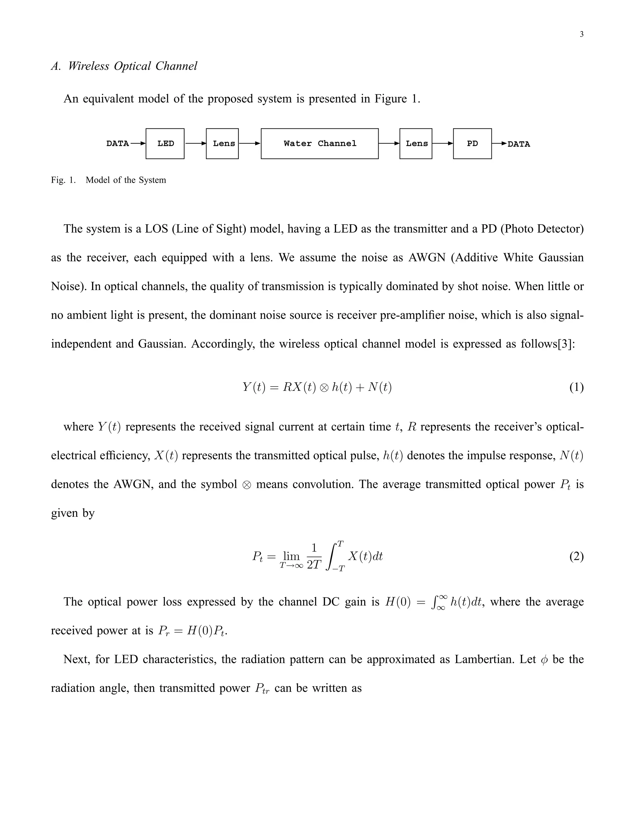
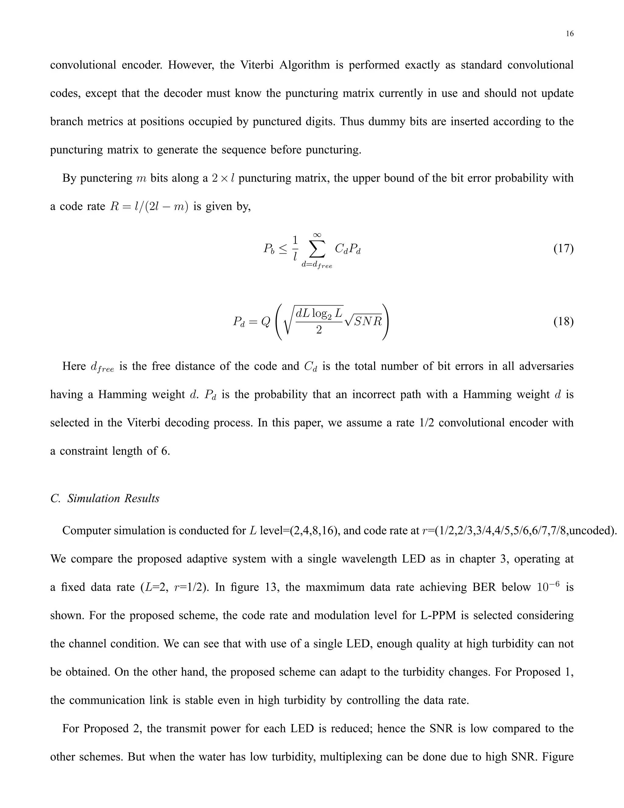
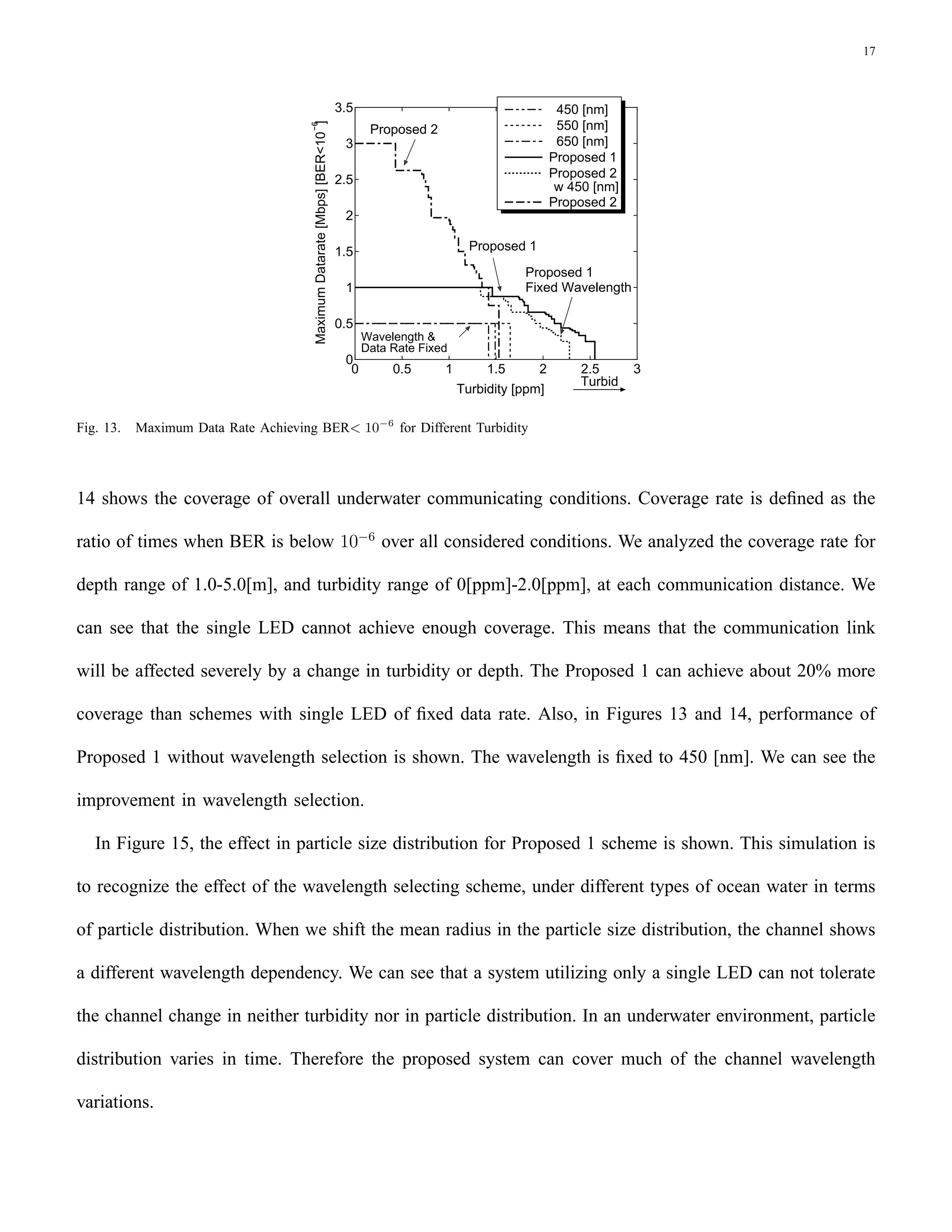
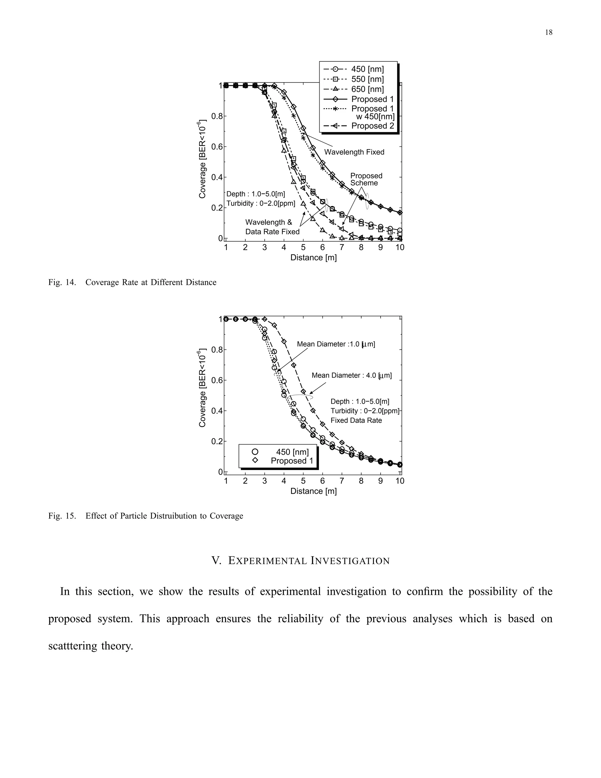
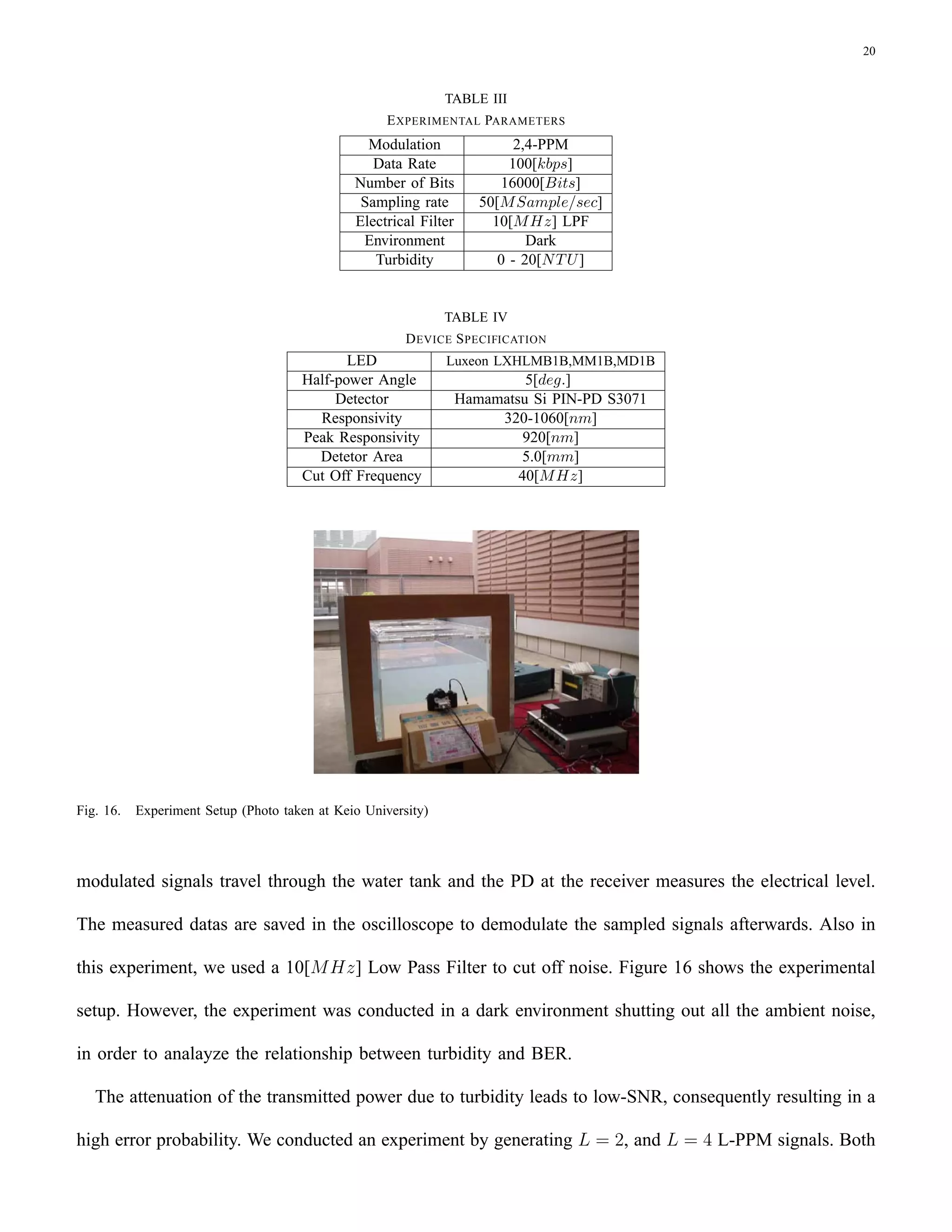
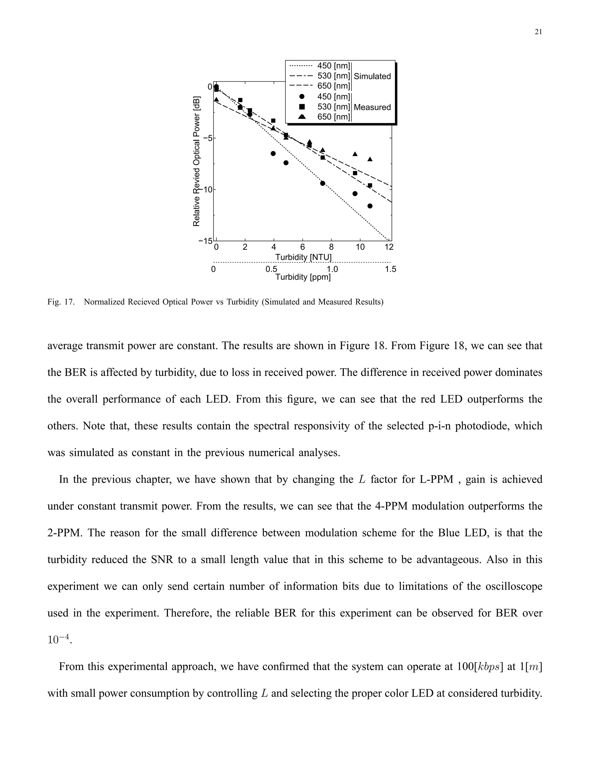
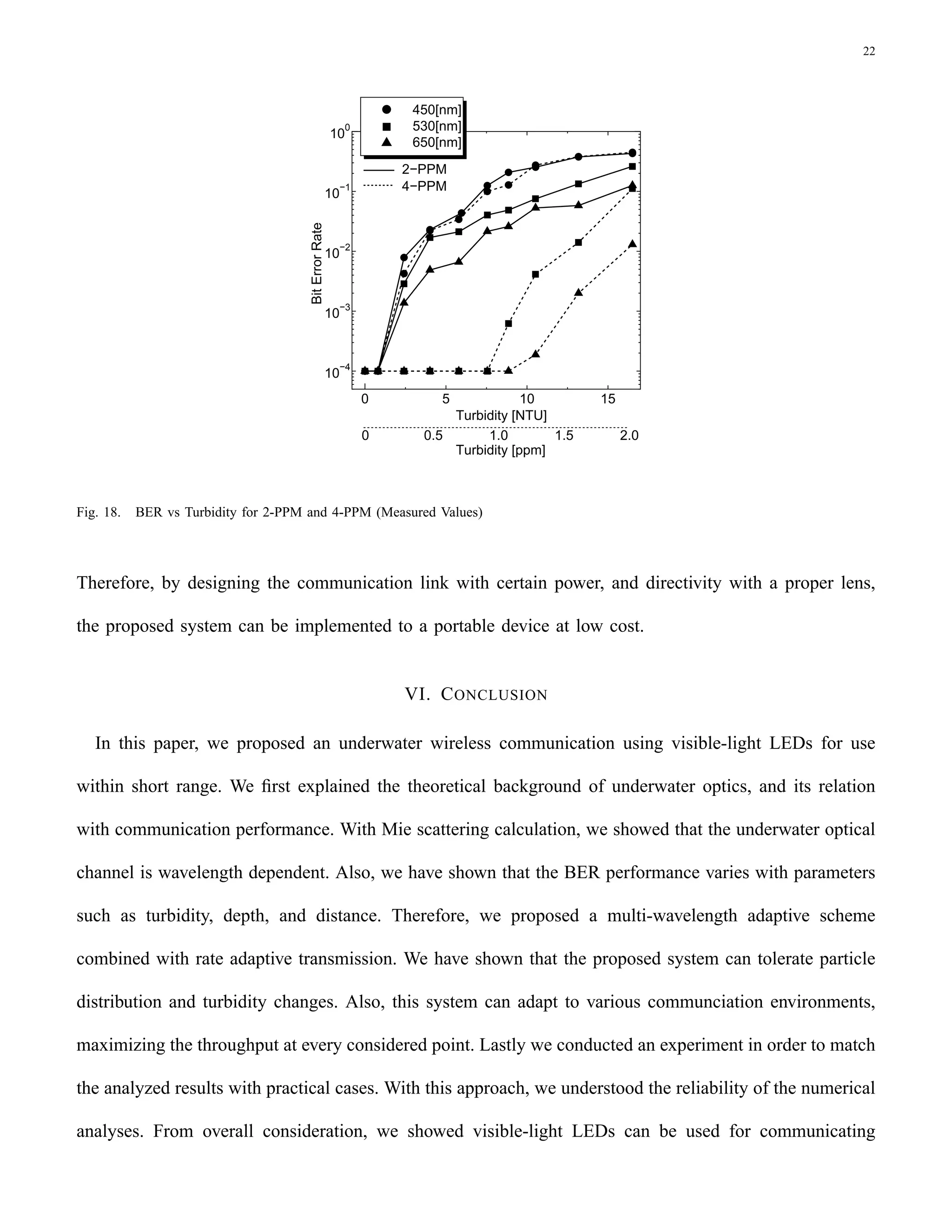
This document proposes using visible light LEDs for short-range underwater wireless communication as an alternative to conventional acoustic systems. It analyzes the performance of such an optical system by modeling the underwater wireless optical channel based on underwater optics. The analysis shows that a single-color LED performs poorly in the wavelength-dependent underwater environment. To address this, the paper proposes a multi-wavelength adaptive scheme combined with rate adaptive transmission that can adapt to channel changes by controlling data rate and power for each wavelength band. An experiment was conducted to confirm the analysis by measuring received power and bit error rate in a turbid water tank.
The document appears to be a scanned receipt from a grocery store listing various food and household items purchased totaling $123.45. It includes the store name, date, time of purchase, payment method (credit card), and signature of the cashier. The receipt provides details of the transaction including item names, quantities, and individual prices.
The document discusses Coulomb's law and its application to calculate the electric field and force between point charges. It also introduces the concepts of electric field intensity and field lines to visualize electric fields. Continuous charge distributions such as line, surface, and volume charges are described. The electric field of an infinite line charge is derived using calculus by treating the line as an integral of point charges.
Video EEG monitoring is performed to determine the type and location of a patient's seizures. It requires hospital admission for 24/7 monitoring over 3-7 days to capture 2-5 typical seizure events. Electrodes are applied to the scalp to connect the patient to monitoring equipment, and family can assist by pressing an event button during seizures. Once enough data is collected, the electrodes are removed and the patient is discharged with safety precautions and follow-up instructions.
This document lists common standard resistor and capacitor values used in electronic circuits. For resistors, it provides values from 1 ohm to 10 megohms in increments from 1% to 5% tolerance. For capacitors, it lists values from 10 picofarads to 10 millifarads in multiples of common numeric prefixes with tolerance ranging from 5% to 20%.
This document summarizes the effects of sleep on EEG patterns. It describes the typical EEG patterns seen in each sleep stage, including: slow rolling eye movements and alpha attenuation in stage 1; sleep spindles, K-complexes, and vertex waves in stage 2; predominant delta activity in stages 3 and 4; and EEG desynchronization along with rapid eye movements in REM sleep. Key findings are outlined for each stage to characterize normal EEG changes that occur during the sleep cycle.
wireless Communication Underwater(Ocean)tanveer alam
Underwater wireless communication uses acoustic signals to transmit digital information through water. Wired connections are not always feasible for underwater experiments due to problems like cable breaks or high costs. Acoustic communication is affected by factors like path loss, noise, multipath propagation, and Doppler spread. Advanced acoustic modems employ techniques like error correction coding to achieve low bit error rates. Underwater acoustic sensor networks use groups of sensors and autonomous underwater vehicles linked by acoustic connections to collaboratively monitor things like pollution, currents, and equipment. Despite progress, limitations remain regarding battery life, bandwidth, and environmental impacts on performance.
VLC uses visible light between 400-800 THz for wireless communication. It has several advantages over RF and IR technologies, such as high data rates, unlimited spectrum, safety, and security. However, VLC requires line of sight between transmitter and receiver, limiting its range. The project implements a VLC system using LEDs and photodiodes connected to microcontrollers for audio and serial communication between devices.
Li-Fi is a new technology that uses light from LED bulbs to transmit data wirelessly. It provides very high data rates of over 500 megabytes per second in labs. Researchers are working on ways to increase data rates further, such as using arrays of LEDs transmitting different data streams simultaneously. Li-Fi has advantages over Wi-Fi such as higher speeds, more available spectrum, more secure communications, and no interference with other electronic devices. It could be used in applications like traffic lights communicating with cars, intrinsically safe environments like oil rigs, and underwater or on airplanes where radio frequencies do not work well.
They are not tattoos.they don't contain any ink nor involve piercing through skin.they can stick to the skin as band aid and consists of sensors.in addition to sensors wireless networking capability provided with which contrlolling can be done from remote computer or smartphone.
Optical Wireless Communications - from the space to the chip.Joaquin Perez
A short introduction to the applications of the OWC in to the short-range to the deep-space applications. Form visible light communications to wearables, OWC is a way to reuse our natural space of communications the free space and the light.
Seminar presented at Universitat Politecnica de Valencia, Spain during the OQCG regular seminars' series, March 2014. by Dr Joaquin Perez
This document is a seminar report on spintronics technology submitted by Shailendra Kumar Singh to his professors Dr. R.S. Meena and Mr. Pankaj Shukla at the University College of Engineering, Rajasthan Technical University in Kota, India. The report provides an introduction to spintronics, which uses the intrinsic spin of electrons in addition to or instead of their charge to create devices that are smaller, more versatile and robust than conventional silicon chips. It also acknowledges the guidance provided by his professors and the facilities provided by the Department of Electronics Engineering.
Electronic skin is a material that mimics human skin and can measure vital signs like heart rate and brain waves. It is made of flexible silicon sensors laminated onto skin like a temporary tattoo. The sensors form a spider web-like circuit that detects pressure, temperature and other bodily functions and transmits the signals to monitoring devices. Electronic skin has applications in healthcare for wound monitoring and in robotics for making machines more human-like. While promising, challenges remain in reducing the cost and enabling reuse of electronic skin technologies.
The document proposes a secure mobile-based voting system that allows voters to cast their votes from anywhere using a mobile device. It outlines the existing electronic and ballot-based voting systems and their drawbacks. The proposed system uses speech recognition and a three-tier architecture to authenticate voters and securely collect, count, and store votes. It aims to improve accessibility, participation, and reduce costs compared to traditional voting methods.
Electronic' skin monitors heart, brain functioncmr cet
The document discusses electronic skin, a new ultra-thin electronic device that can attach to the skin like a temporary tattoo. It can measure vital signs like electrical heart activity and brain waves. Researchers developed it to reduce wires and make medical monitoring more compact. Electronic skin uses tiny sensors and a "spider web" circuitry design made of silicon filaments. It transmits the recorded body signals to a receiver. Researchers believe it could one day control virtual screens to monitor health and even stimulate skin for smart bandages.
This document presents information on underwater wireless communication. It discusses how acoustic waves can be used for underwater wireless transmission instead of radio waves due to water's inhibiting effects on radio waves. The document outlines the working, applications, advantages and disadvantages of underwater wireless communication using acoustic waves and acoustic modems. It provides figures showing different acoustic modems and the network architecture. The conclusion states that underwater wireless using acoustic waves can achieve high data rates with lower path loss compared to other methods.
The document discusses touchless touchscreen technology, including touch walls that use infrared lasers to scan surfaces, touchless UIs that sense finger movements in 3D space without touching the screen, and touchless monitors that detect 3D motion without sensors. It provides examples of touchless technology inspired by Minority Report including eye tracking, gesture recognition, and motion sensing devices. The document concludes that touchless interfaces could transform bodies into virtual input devices in the future.
A touchless touchscreen uses optical pattern recognition and a solid state optical matrix sensor to detect hand movements in front of the screen instead of requiring physical contact. The sensor is made up of a matrix of pixels, each with photodiodes that convert incoming light to electric charge. The sensor generates signals that are processed by a digital image processor to provide output and interpret gestures without the user touching the display. Touchless touchscreens offer advantages like not wearing down the screen surface and allowing control from a distance, though sightline remains a limitation currently. The technology continues developing with potential for full body control of devices in the future.
Touchless technology Seminar PresentationAparna Nk
This document discusses touchless technology that allows users to interact with screens without physically touching them. It describes a touchless monitor developed by TouchKo, White Electronics Designs, and Groupe 3D that uses sensors around the screen to detect 3D motions and interpret them as on-screen interactions. The document also mentions several other touchless technologies like the Touchless SDK, Touch Wall, eye tracking devices, gesture recognition tools, and motion sensors that enable touchless control of devices.
Topic on Underwater Communication which includes both underwater wireless and wired communication . A full detailed overview about the topic has been given. Pictures are given to visualize the topic in better way. Covers a major potion like Hydrophones and SONAR. Can be presented as a seminar topic as well .
Underwater optical communication is a promising alternative to acoustic methods for underwater wireless communication. Radio waves do not propagate well underwater, so optical methods using lasers and LEDs can provide line-of-sight transmission of data, video and signals for vehicle control. Several factors influence the performance of underwater optical links, including absorption and scattering by water constituents like phytoplankton and dissolved organic matter, as well as scattering from suspended particles.
Underwater acoustic communication is a technique of sending and receiving message below water.[1] There are several ways of employing such communication but the most common is using hydrophones. Under water communication is difficult due to factors like multi-path propagation, time variations of the channel, small available bandwidth and strong signal attenuation, especially over long ranges. In underwater communication there are low data rates compared to terrestrial communication, since underwater communication uses acoustic waves instead of electromagnetic waves.
This document discusses the history, advantages, need, implementation, current devices and future of wireless communication. It covers the evolution of wireless technologies from early cellular phones to modern Wi-Fi and Bluetooth, explaining how wireless networks have become essential due to their convenience and mobility compared to wired connections. The future of wireless communication looks to advance connectivity through emerging technologies.
Wireless communication allows for freedom from wires and instantaneous communication without physical connections. It provides global coverage for communication that can reach areas where wiring is infeasible or costly. Wireless communication transmits voice and data using radio waves without wires. It uses different frequency channels that can transmit information independently and in parallel. While wireless communication provides mobility and flexibility, it also faces security and physical obstruction issues compared to wired communication.
Human: Thank you for the summary. It effectively captured the key points about wireless communication in just 3 sentences as requested.
- Quantum dots are semiconductor nanoparticles that exhibit unique optical and electronic properties due to their small size (around 4 million dots fit in a 2cm area).
- Current research is investigating applications for quantum dots in areas like displays, solar cells, computer storage, and programmable matter. Quantum dot displays could produce richer colors than LCDs and be integrated into flexible or multi-purpose screens. Quantum dot solar cells may lead to higher efficiency photovoltaics.
- The future potential applications of quantum dots include foldable or color-changing screens, invisible solar coatings, vastly increased computer storage capacity, and materials with customizable properties through electron manipulation at the quantum level.
Virtual reality is a user interface that involves real-time simulation and interactions through sensory channels to immerse users in virtual environments. It has its origins in flight simulators from the 1950s and early prototypes in the 1960s, with commercial development beginning in the late 1980s. Current applications of VR include movies, video games, and education/training. Emerging technologies like Project Natal, CAVE systems, and the Nintendo Wii are pushing the boundaries of VR by enabling more natural physical interaction. While the future is uncertain, VR is expected to continue evolving entertainment and other industries through immersive experiences.
Wireless communication allows transfer of information between two or more points without wires. Common forms of wireless communication include Bluetooth, NFC, WiFi, and LiFi. Bluetooth uses short-range radio links to connect devices like headphones, keyboards and printers. It transmits data via low-power radio waves at a frequency of 2.45 gigahertz and can connect up to eight devices simultaneously. NFC operates at a very short range through electromagnetic induction, allowing data exchange when devices are touched or in close proximity. It is commonly used for contactless payments and data sharing. WiFi enables internet access from any location within range of a base station using radio waves, providing cable-like speeds wirelessly. LiFi is a wireless optical
Wireless technology allows for the transfer of information between two points not physically connected by wires. It includes technologies like radio frequency communication, microwave communication, infrared communication, cellular networks, WiFi, and Bluetooth. Some important developments in wireless technology history include Alexander Graham Bell and Charles Sumner Tainter inventing the photophone in 1880, the first wireless telephone, and Heinrich Hertz demonstrating electromagnetic waves in 1888, proving James Clerk Maxwell's electromagnetic theory. Modern applications of wireless technology include mobile phones, wireless internet access, and wireless energy transfer.
Circuits for Optical Based Line of Sight Voice CommunicationjournalBEEI
We present here line of sight communication between a person and his neighbour with the help of optical signal produced by a laser torch which act as a carrier. It is therefore a wireless communication and the transmission can go up to 500 meters. We used photodiode to receive the signal at the receiver. The transmitter circuit comprises condenser microphone transistor amplifier BC547 followed by an op-amp stage built around µA741. When we give a voice signal from the mike, it converts the voice signal into the electrical signal. This electrical signal is fed to IC741 (op-amp) for amplification. The gain of the op-amp can be controlled with the help of 1-mega-ohm potentiometer. The AF output from IC is coupled to the base of a class B amplifier which, in turn, modulates the signal. The transmitter uses 5V power supply. However, the 3-volt laser torch (after removal of its battery) can be directly connected to the circuit-with the body of the torch connected to the class B. The photodiode converts the optical signal into electrical signal and again this signal is amplified using IC741 and a combination of class B push pull amplifiers. The receiver circuit uses an NPN photodiode as the light sensor that is followed by a two-stage transistor preamplifier and IC741 based audio Power amplifier. The receiver does not need any complicated alignment. Just keep the photodiode oriented towards the remote transmitter’s laser point and adjust the volume control for a clear sound. The sensor must not directly face the sun.
This document summarizes key aspects of PIN photodiodes. It describes the physical principles of how PIN photodiodes operate by separating photo-generated carriers across a reverse-biased junction to produce a photocurrent. It also discusses photodiode characteristics like quantum efficiency and responsivity. Additionally, it covers noise sources in photodetector circuits including quantum, dark current, leakage current, and thermal noise. The document also examines photodiode response time and how the junction capacitance and absorption coefficient impact the rise and fall times. Finally, it compares different PIN photodiode structures like front vs rear illuminated and diffused vs mesa etched designs.
The document discusses optical fiber transmission and its advantages over other transmission mediums. It describes how optical fibers conduct light using total internal reflection. It also summarizes the key components used in optical fiber communication systems including optical sources like LEDs and lasers, photodetectors, and various types of optical fibers and their characteristics such as attenuation and dispersion. The document highlights how optical fiber transmission provides high bandwidth and capacity.
PHOTODETECTORS - CALCULATION OF SENSTIVITY OF PbO AS A DIRECT CONVERSION MATE...Adeagbo Bamise
This document discusses the sensitivity of PbO as a direct conversion material in x-ray detection. It begins by introducing photodetectors and how they convert radiation into an electrical signal through the creation of electron-hole pairs. It then examines the basic principles and characteristics of several types of photodetectors, including pn junction photodiodes, pin photodiodes, and avalanche photodiodes. Finally, it discusses x-ray photoconductors and the metrics used to evaluate their performance as x-ray detectors, using PbO as a case study material.
1. Transmission electron microscopes use electrons instead of light to image samples, allowing for much higher resolution down to the nanometer scale.
2. The wavelength of electrons can be decreased by increasing the accelerating voltage, improving resolution according to the Rayleigh criterion.
3. Factors like vacuum quality, beam alignment, and sample thickness influence image quality in transmission electron microscopy.
The document provides an introduction to optoelectronic devices, including their operation and key properties. It discusses:
1) The wave nature of light and how it is described by Maxwell's equations.
2) Polarization and the electromagnetic spectrum, including visible, infrared, and ultraviolet light ranges.
3) Types of optoelectronic devices like p-n junction diodes, heterojunction diodes, laser diodes, photoconductive cells, pin photodiodes, avalanche photodiodes, and photovoltaic cells. It provides details on their principles, structures, and applications.
DEVELOPMENT OF OPTICAL PARAMETER CALCULATIONS OF THE PROBES IN WATERDr. Ved Nath Jha
This document describes the development of optical parameter calculations for probes used in water sensing. Three probes (a, b, c) of varying nanoparticle size were developed and their plasma and collision wavelengths were calculated based on experimental measurements in water and air. The probes showed decreasing collision wavelength but nearly constant plasma wavelength with increasing nanoparticle size. Models were developed to calculate output intensity based on the dielectric constant of the surrounding medium. Distinct dips in output intensity correlated with different dielectric components when mixtures were tested, showing ability to detect multiple impurities simultaneously. The probes function best for dielectric constants between 1.4-2.0 and silver nanoparticles provide sensitivity towards targeted impurities in water quality monitoring.
Optical detectors details and technologies with formulasSyed Kamran Haider
This document presents information on optical detectors. It begins with an overview of optical communication systems and fiber optic architecture. It then discusses the key components of optical receivers including light sources, detectors, and fiber-optic cables. Common types of optical detectors are photo diodes (PIN and APD). PIN diodes have good linearity and speed but lower sensitivity, while APDs provide internal gain but more noise. Characteristics like responsivity, bandwidth, capacitance, and noise are examined. Factors influencing detector performance and tradeoffs between bandwidth and efficiency are also summarized.
This document summarizes an MPhys project report on optical coherence tomography using a Fourier domain method. The student, Riccardo William Monfardini, built an OCT apparatus and used it to measure the thickness of a microscope cover glass, determined to be 154.33±4.70μm. The report describes the theory behind OCT, including Fourier domain techniques, and details the student's method of using the apparatus to indirectly measure the glass thickness.
This paper deals with the Internal quantum efficiency of ITO, CdTe, ZnO/a-Si, SnS/Si, CdS /CIGS, FTO/CZTS based of material photodiode with a ITO/CdTe, ZnO/a-Si, SnS/Si, CdS /CIGS, FTO/CZTS heterojunction structure. Along with information on device characteristics, applications and properties, we provide a comparative device analysis between this type of photodiode and the slightly more efficient ITO/CdTe, ZnO/a-Si, SnS/Si, CdS /CIGS, FTO/CZTS heterojunction structure. We will get the clear concept of the relation between of generated current & load voltage. We hope, we will get a clear explanation about the effect of photodiode light intensity & wavelength on the solar efficiency. In this project we will analyze the Quantum efficiency of a photodiode.
Average symbol error rate analysis of reconfigurable intelligent surfaces-as...IJECEIAES
Optical wireless communication (OWC) has attracted significant interest recently in academia and industry. Free-space optical (FSO) communication systems are where free space acts as a communication channel between transceivers that are line of sight (LOS) for the successful transmission of optical signals. The FSO transmissions through the atmosphere, nevertheless, bring significant challenges, besides the uncertainty of atmospheric channels, especially the signal fading due to the atmospheric turbulence, attenuation and pointing errors caused by the random beam misalignments between transceivers, signal obstruction due to buildings or trees can pre-vent the transmitted message to reach the destination. This study theoretically investigates the average symbol error rate (ASER) of reconfigurable intelligent surfaces (RIS) assisted FSO link over log-normal turbulence channels. The RIS effect is examined by considering the influence of link distance, transmitted optical power, and quadrature amplitude modulation (QAM) scheme on the ASER.
The document discusses photodetectors and the principles of p-n junction photodiodes. It describes the depletion region of a reverse biased p-n junction and how electron-hole pairs generated by photons are separated by the electric field. It also discusses pin photodiodes and how their intrinsic region allows for higher quantum efficiency and modulation frequencies compared to p-n junction photodiodes. Absorption coefficients of various semiconductor materials are shown as well as how direct and indirect bandgap materials differ in photon absorption.
This document summarizes dispersion management in optical fiber communication. It discusses the basic components of an optical fiber including the core, cladding, buffer, and jacket. It also describes optical transmitters such as lasers and LEDs, as well as optical receivers such as photo detectors. The document outlines the main types of dispersion in fibers including material dispersion, waveguide dispersion, and polarization mode dispersion. It compares Gaussian and super Gaussian pulses and how super Gaussian pulses can reduce dispersion, especially at higher data transmission rates. In conclusion, the document provides a basic overview of optical fiber communication and dispersion management techniques.
This document discusses characteristics of the optical channel for underwater optical wireless communication systems. It summarizes that underwater optical communication suffers from light attenuation and scattering as it propagates through water. The key factors affecting the optical channel are the refractive index of water, absorption and scattering coefficients. The receiver signal power, link margin, data rate, and signal-to-noise ratio are calculated based on the optical path loss and properties of the underwater channel. The results show these communication parameters decrease with increasing refractive index and distance in the underwater link.
1) Underwater communication faces challenges due to the medium but has progressed with acoustic and optical modulation/demodulation.
2) Channel modeling is important to evaluate techniques before development and reduces hardware costs. Common models include additive noise, acoustic, and optical channels.
3) Acoustic waves best communicate underwater but have limited bandwidth while optical has more bandwidth but higher attenuation. Hybrid systems may improve performance.
1) Underwater communication faces challenges due to the medium but has progressed with acoustic and optical modulation/demodulation.
2) Channel modeling is important to evaluate techniques before implementation and reduces hardware costs. Common models include the additive noise channel and radiative transfer equation models.
3) Acoustic communication uses sound waves and has advantages of long range but limited bandwidth. Optical uses light with higher bandwidth but more attenuation. Hybrid systems may improve performance.
Measurement of energy loss of light ions using silicon surface barrier detectoreSAT Publishing House
IJRET : International Journal of Research in Engineering and Technology is an international peer reviewed, online journal published by eSAT Publishing House for the enhancement of research in various disciplines of Engineering and Technology. The aim and scope of the journal is to provide an academic medium and an important reference for the advancement and dissemination of research results that support high-level learning, teaching and research in the fields of Engineering and Technology. We bring together Scientists, Academician, Field Engineers, Scholars and Students of related fields of Engineering and Technology
This document provides information about a physics course titled "WAVE OPTICS/MODERN PHYSICS" taught by S.N. Dash at NIT Rourkela. The 4 credit course covers topics like interference, diffraction, electromagnetic waves, polarization, and quantum mechanics. Exams and assignments make up the evaluation, with the midterm worth 30%, end term 50%, and assignments 20%. Letter grades are assigned based on percentage scores. The document also provides the instructor's contact information and outlines course topics, textbooks, and assignments.
This is the project report for my internship at HBCSE-TIFR. The project describes a low-cost method for analysing the spectrum of LEDs and determining the wavelength.
Similar to Short Range Underwater Communication Using Visible Led (20)
Introducing BoxLang : A new JVM language for productivity and modularity!Ortus Solutions, Corp
Just like life, our code must adapt to the ever changing world we live in. From one day coding for the web, to the next for our tablets or APIs or for running serverless applications. Multi-runtime development is the future of coding, the future is to be dynamic. Let us introduce you to BoxLang.
Dynamic. Modular. Productive.
BoxLang redefines development with its dynamic nature, empowering developers to craft expressive and functional code effortlessly. Its modular architecture prioritizes flexibility, allowing for seamless integration into existing ecosystems.
Interoperability at its Core
With 100% interoperability with Java, BoxLang seamlessly bridges the gap between traditional and modern development paradigms, unlocking new possibilities for innovation and collaboration.
Multi-Runtime
From the tiny 2m operating system binary to running on our pure Java web server, CommandBox, Jakarta EE, AWS Lambda, Microsoft Functions, Web Assembly, Android and more. BoxLang has been designed to enhance and adapt according to it's runnable runtime.
The Fusion of Modernity and Tradition
Experience the fusion of modern features inspired by CFML, Node, Ruby, Kotlin, Java, and Clojure, combined with the familiarity of Java bytecode compilation, making BoxLang a language of choice for forward-thinking developers.
Empowering Transition with Transpiler Support
Transitioning from CFML to BoxLang is seamless with our JIT transpiler, facilitating smooth migration and preserving existing code investments.
Unlocking Creativity with IDE Tools
Unleash your creativity with powerful IDE tools tailored for BoxLang, providing an intuitive development experience and streamlining your workflow. Join us as we embark on a journey to redefine JVM development. Welcome to the era of BoxLang.
As AI technology is pushing into IT I was wondering myself, as an “infrastructure container kubernetes guy”, how get this fancy AI technology get managed from an infrastructure operational view? Is it possible to apply our lovely cloud native principals as well? What benefit’s both technologies could bring to each other?
Let me take this questions and provide you a short journey through existing deployment models and use cases for AI software. On practical examples, we discuss what cloud/on-premise strategy we may need for applying it to our own infrastructure to get it to work from an enterprise perspective. I want to give an overview about infrastructure requirements and technologies, what could be beneficial or limiting your AI use cases in an enterprise environment. An interactive Demo will give you some insides, what approaches I got already working for real.
Keywords: AI, Containeres, Kubernetes, Cloud Native
Event Link: https://meine.doag.org/events/cloudland/2024/agenda/#agendaId.4211
Discover the Unseen: Tailored Recommendation of Unwatched ContentScyllaDB
The session shares how JioCinema approaches ""watch discounting."" This capability ensures that if a user watched a certain amount of a show/movie, the platform no longer recommends that particular content to the user. Flawless operation of this feature promotes the discover of new content, improving the overall user experience.
JioCinema is an Indian over-the-top media streaming service owned by Viacom18.
QR Secure: A Hybrid Approach Using Machine Learning and Security Validation F...AlexanderRichford
QR Secure: A Hybrid Approach Using Machine Learning and Security Validation Functions to Prevent Interaction with Malicious QR Codes.
Aim of the Study: The goal of this research was to develop a robust hybrid approach for identifying malicious and insecure URLs derived from QR codes, ensuring safe interactions.
This is achieved through:
Machine Learning Model: Predicts the likelihood of a URL being malicious.
Security Validation Functions: Ensures the derived URL has a valid certificate and proper URL format.
This innovative blend of technology aims to enhance cybersecurity measures and protect users from potential threats hidden within QR codes 🖥 🔒
This study was my first introduction to using ML which has shown me the immense potential of ML in creating more secure digital environments!
Lee Barnes - Path to Becoming an Effective Test Automation Engineer.pdfleebarnesutopia
So… you want to become a Test Automation Engineer (or hire and develop one)? While there’s quite a bit of information available about important technical and tool skills to master, there’s not enough discussion around the path to becoming an effective Test Automation Engineer that knows how to add VALUE. In my experience this had led to a proliferation of engineers who are proficient with tools and building frameworks but have skill and knowledge gaps, especially in software testing, that reduce the value they deliver with test automation.
In this talk, Lee will share his lessons learned from over 30 years of working with, and mentoring, hundreds of Test Automation Engineers. Whether you’re looking to get started in test automation or just want to improve your trade, this talk will give you a solid foundation and roadmap for ensuring your test automation efforts continuously add value. This talk is equally valuable for both aspiring Test Automation Engineers and those managing them! All attendees will take away a set of key foundational knowledge and a high-level learning path for leveling up test automation skills and ensuring they add value to their organizations.
[OReilly Superstream] Occupy the Space: A grassroots guide to engineering (an...Jason Yip
The typical problem in product engineering is not bad strategy, so much as “no strategy”. This leads to confusion, lack of motivation, and incoherent action. The next time you look for a strategy and find an empty space, instead of waiting for it to be filled, I will show you how to fill it in yourself. If you’re wrong, it forces a correction. If you’re right, it helps create focus. I’ll share how I’ve approached this in the past, both what works and lessons for what didn’t work so well.
GlobalLogic Java Community Webinar #18 “How to Improve Web Application Perfor...GlobalLogic Ukraine
Під час доповіді відповімо на питання, навіщо потрібно підвищувати продуктивність аплікації і які є найефективніші способи для цього. А також поговоримо про те, що таке кеш, які його види бувають та, основне — як знайти performance bottleneck?
Відео та деталі заходу: https://bit.ly/45tILxj
AppSec PNW: Android and iOS Application Security with MobSFAjin Abraham
Mobile Security Framework - MobSF is a free and open source automated mobile application security testing environment designed to help security engineers, researchers, developers, and penetration testers to identify security vulnerabilities, malicious behaviours and privacy concerns in mobile applications using static and dynamic analysis. It supports all the popular mobile application binaries and source code formats built for Android and iOS devices. In addition to automated security assessment, it also offers an interactive testing environment to build and execute scenario based test/fuzz cases against the application.
This talk covers:
Using MobSF for static analysis of mobile applications.
Interactive dynamic security assessment of Android and iOS applications.
Solving Mobile app CTF challenges.
Reverse engineering and runtime analysis of Mobile malware.
How to shift left and integrate MobSF/mobsfscan SAST and DAST in your build pipeline.
Northern Engraving | Modern Metal Trim, Nameplates and Appliance PanelsNorthern Engraving
What began over 115 years ago as a supplier of precision gauges to the automotive industry has evolved into being an industry leader in the manufacture of product branding, automotive cockpit trim and decorative appliance trim. Value-added services include in-house Design, Engineering, Program Management, Test Lab and Tool Shops.
What is an RPA CoE? Session 1 – CoE VisionDianaGray10
In the first session, we will review the organization's vision and how this has an impact on the COE Structure.
Topics covered:
• The role of a steering committee
• How do the organization’s priorities determine CoE Structure?
Speaker:
Chris Bolin, Senior Intelligent Automation Architect Anika Systems
Connector Corner: Seamlessly power UiPath Apps, GenAI with prebuilt connectorsDianaGray10
Join us to learn how UiPath Apps can directly and easily interact with prebuilt connectors via Integration Service--including Salesforce, ServiceNow, Open GenAI, and more.
The best part is you can achieve this without building a custom workflow! Say goodbye to the hassle of using separate automations to call APIs. By seamlessly integrating within App Studio, you can now easily streamline your workflow, while gaining direct access to our Connector Catalog of popular applications.
We’ll discuss and demo the benefits of UiPath Apps and connectors including:
Creating a compelling user experience for any software, without the limitations of APIs.
Accelerating the app creation process, saving time and effort
Enjoying high-performance CRUD (create, read, update, delete) operations, for
seamless data management.
Speakers:
Russell Alfeche, Technology Leader, RPA at qBotic and UiPath MVP
Charlie Greenberg, host
QA or the Highway - Component Testing: Bridging the gap between frontend appl...zjhamm304
These are the slides for the presentation, "Component Testing: Bridging the gap between frontend applications" that was presented at QA or the Highway 2024 in Columbus, OH by Zachary Hamm.
"NATO Hackathon Winner: AI-Powered Drug Search", Taras KlobaFwdays
This is a session that details how PostgreSQL's features and Azure AI Services can be effectively used to significantly enhance the search functionality in any application.
In this session, we'll share insights on how we used PostgreSQL to facilitate precise searches across multiple fields in our mobile application. The techniques include using LIKE and ILIKE operators and integrating a trigram-based search to handle potential misspellings, thereby increasing the search accuracy.
We'll also discuss how the azure_ai extension on PostgreSQL databases in Azure and Azure AI Services were utilized to create vectors from user input, a feature beneficial when users wish to find specific items based on text prompts. While our application's case study involves a drug search, the techniques and principles shared in this session can be adapted to improve search functionality in a wide range of applications. Join us to learn how PostgreSQL and Azure AI can be harnessed to enhance your application's search capability.
Short Range Underwater Communication Using Visible Led
1. 1
Short-Range Underwater Wireless Communication
Using Visible Light LEDs
Yousuke Ito, Nonmember, Shinichiro Haruyama, Member,
and Masao Nakagawa, Fellow, IEEE
Abstract
In this paper, we propose an underwater wireless communication technique using visible light LEDs for use
in short range. As an alternative system against conventional acoustic systems, optical communication can achieve
high data rate. We analyzed the system performance by modeling the channel based on underwater optics. Through
this analysis, we show that a single color LED is very weak in a wavelength dependent underwater channel. To
overcome this problem, in this paper we propose a multi-wavelength adaptive scheme combined with rate adaptive
transmission. The proposed system can adapt to the channel by considering the change in power for each wavelength
band, and controlling the data rate. Lastly, an experiment has been conducted to confirm the analyzed results with
practical cases by measuring the received power and BER in turbid water tank. We have shown that the numerical
analyses are reliable, and the possibility of such system.
Index Terms
Underwater Communication, Visible Light Communication, LED, Rate Adaptive Transmission.
I. I NTRODUCTION
N
OWADAYS, acoustic technology is mostly used for establishing wireless communication link
among divers and ships, or sending long range remote signals. This is because sound waves travel
through water faster than in air, receiving very little attenuation. However, due to frequency attenuation
characteristic of acoustic waves in water, it is difficult to expand its bandwidth. Therefore, acoustic
Manuscript created March 1st, 2006
The authors are with the Faculty of Science and Technology, Keio University.
2. 2
approach can not achieve high data rate, and also portable communication devices are difficlut to be
designed at a low cost.
However, there are demands for high quality, high speed communication links even for short distances
within few meters. For example, such demands are in high quality voice communication between divers,
and in data transmission of video streaming and sensing datas. Optical communication, which can be
operated at over hundreds of MHz, can meet these demands. Also, it is known that light in the visible
region has the least attenuation in water absorption. A voice communicating system utilizing laser beams
has been proposed[1], however it is rather unrealistic and dangerous to implent a laser in a man-use
devices underwater, as the optical axis needs to be fixed all the time. Moreover, laser diodes are an
expensive device. Therefore, in this paper, we propose a system utilizing a modulated visible light LED
(Light Emitting Diode) for underwater wireless communication. LEDs have low power consumption for
a given power input, low operating voltage, long lifetime, and low cost. Also they can be modulated at
high speed providing bit rate up to 100Mbps. Thus, by using LEDs as a modulated source, a reliable high
speed communication system can be implemented in a portable device at a very low cost.
The purpose of this paper is to understand the underwater optical channel, and its effect on the
communication link. For this analysis, we apply Mie scattering theory[2]. After gaining knowledge
of the channel, a new system is proposed to adapt to several problems among underwater wireless
optical channel. As a new system, we propose a multi-wavelength adaptive scheme combined with
rate adaptive transmission using plural LEDs. Also, an experimental investigation has been conducted
to compare the analyzed results with practical cases, in turbid water. Note that this paper is not interested
in accurately modeling the underwater optical channel, but focusing on bonding the two areas; optical
wireless communication theory and underwater optics.
II. C HANNEL M ODEL
In this section, underwater wireless optical channel model based on underwater optics is presented.
3. 3
A. Wireless Optical Channel
An equivalent model of the proposed system is presented in Figure 1.
DATA LED Lens Water Channel Lens PD DATA
Fig. 1. Model of the System
The system is a LOS (Line of Sight) model, having a LED as the transmitter and a PD (Photo Detector)
as the receiver, each equipped with a lens. We assume the noise as AWGN (Additive White Gaussian
Noise). In optical channels, the quality of transmission is typically dominated by shot noise. When little or
no ambient light is present, the dominant noise source is receiver pre-amplifier noise, which is also signal-
independent and Gaussian. Accordingly, the wireless optical channel model is expressed as follows[3]:
Y (t) = RX(t) ⊗ h(t) + N (t) (1)
where Y (t) represents the received signal current at certain time t, R represents the receiver’s optical-
electrical efficiency, X(t) represents the transmitted optical pulse, h(t) denotes the impulse response, N (t)
denotes the AWGN, and the symbol ⊗ means convolution. The average transmitted optical power Pt is
given by
1 T
Pt = lim X(t)dt (2)
T →∞ 2T −T
∞
The optical power loss expressed by the channel DC gain is H(0) = ∞
h(t)dt, where the average
received power at is Pr = H(0)Pt .
Next, for LED characteristics, the radiation pattern can be approximated as Lambertian. Let φ be the
radiation angle, then transmitted power Ptr can be written as
4. 4
m+1
Ptr (φ) = Pt cosm (φ)
2π
ln2
m = − (3)
ln cos Φ1/2
where m denotes the directivity of the radiation pattern, which is defined by the semi-angle at half
power Φ1/2 of the LED.
Now, we can define our system’s optical channel gain as
⎧
⎪ (m + 1)A
⎪
⎨ cosm (φ)Ts (ψ)g(ψ)cosψ 0 ≤ ψ ≤ Ψ
H(0) = 2πd2 (4)
⎪
⎪
⎩ 0 ψ > Ψ.
A represents the area of PD, d is the distance between the transmitter and the receiver, ψ represents
the incident angle, Ts (ψ) represents the optical filter gain, and g(ψ) represents the lens gain where Ψ is
the FOV (Field Of View). The lens gain g(ψ) can be expressed with its refractive index n as
n2
g(ψ) = 0≤ψ≤Ψ (5)
sin ψ 2
B. Underwater Optics
As light travels through a medium, its intensity decreases due to absorption and scattering occurred by
water molecules and dissolved particles. If a light in wavelength λ has an intensity I(λ) and travels a
distance dr, letting dIλ be the attenuation in intensity, then Beer’s Law can be expressed as follows[1]:
dI(λ) = −K(λ)I(λ)dr (6)
Integrating distance r from 0 to d, and letting I0 (λ) be the intensity of light at r = 0, Eq.6 can be
written as
I(λ) = I0 (λ) exp(−K(λ) · d) (7)
K(λ) is the attenuation coefficient, which in this paper defined as
K(λ) = aw (λ) + bp (λ)C (8)
5. 5
where aw (λ) is the absorption of water, bp (λ) is the scattering of dissolved particles of light in
wavelength λ. Note that the scattering of water molecules and absorption of particles are neglected in
this paper, as they are small enough compared to the parameters in Eq.(8). Also in Eq.(8), C denotes the
particle concentration. In this paper, we define it ppm (parts per million) of the existing particles in unit
volume. We refer to this parameter as turbidity, since it determines the visiblity range in ocean water.
From past measurements, it is known that most particles dissolved in ocean water, are in the order
of μm in size. The scattering process of optical wavelengths close to this length can be completely
explained by Mie Scattering theory[2]. Therefore, for multiple scattering calculation we apply this theory.
Let us assume a particle of radius r with a refractive index of m(= mr − mi i). As mentioned above, the
absorption of particles is neglected, thus mi equals 0. We define the scattering efficiency Qsca , as the ratio
of scattering cross-section and geometrical cross-section πr2 . According to Mie Theory, the efficiency is
a function of the size parameter x = 2πr/λ and refractive index m of the particle. If we let the particle
size distribution be n(r)dr and assuming the radius range of r ∼ r + dr, the scattering coefficient bp (λ)
can be expressed as
r2
bp (λ) = πr2 Qsca (m, x)n(r)dr (9)
r1
C. Signal to Noise Ratio
The communication quality of the system is determined by the SNR (Signal to Noise Ratio)[3].
R2 Pr2
SN R = (10)
N
where N is the power spectral density of noise, which is defined by the variance as follows.
2 2
N = σshot + σcir (11)
2
σshot denotes the shot noise in the received signal and the ambient light. In this paper we assume a
2
AWGN over the equivalent noise bandwidth B. B depends on the modulation scheme. Therefore, σshot
is expressed as
6. 6
2
σshot = 2qRPr B + 2qRPn I2 B (12)
λ1
Pn = Ts An2 pn (λ) exp(−Kλ ddep )dλ (13)
λ2
where q represents the electric charge (1.6 ×10⁻¹⁹ ), and the I2 is the noise factor due to the thermal
noise in the feedback curcuit. In Eq.13, Pn is the overall ambient light power, pn (λ) is the spectral
irradiance at sea level, ddep represents the depth from sea level. λ1 and λ2 are determined by the optical
2
filter bandwidth. Also in Eq.11, σcir represents the circuit noise, which consists of a thermal noise and the
amplifier noise. In this paper, we assume the use of a p-i-n/FET (Field Effect Transistor) transimpedance
receiver. We neglect the noise contributions from gate leakage current and 1/f noise. The circuit noise
variance is given as follows[3].
2 4KT 4KT Γ
σcir = 2πηAI2 B 2 + (2πηA)2 I3 B 3 (14)
G gm
K represents the Boltzmann’s constant, T is the absolute temperature, G is the open-loop voltage gain
of the amplifier, η is the fixed capacitance of photo detector per unit area, gm is the FET transconductance,
Γ represents the channel noise factor, and I3 represents the noise factor due to the thermal noise in the
channel of the FET[3].
Considering the wavelength dependency of the ocean water, the optical signal is attenuated differently
on each wavelength. Thus we can redefine Eq.10 as,
2
λ1
λ2
(R(λ)Pt (λ)H(0) exp(−K(λ)d)dλ
SN R = λ1
(15)
λ2
N (λ)dλ
Pt (λ) and N (λ) represent the spectral distribution of the LED and received noise, respectively. From
Eq.13, the greater the depth, the greater the ambient light spectrum shows wavelength dependency.
Therefore, the overall noise can be considered as a function of wavelength.
7. 7
III. S YSTEM P ERFORMANCE
Here we discuss the system performance through numerical analysis. Note that this paper does not
focus on an accurate modeling of the underwater optical channel. Therefore, we will use parameters to
define a general model to explain the further communication performance. Also, the communication model
presented in this paper can be tuned and approximated to different ocean optic models, by substituting
parameters defined in section 2.
First, we calculate the attenuation coefficient K(λ), as described in the previous chapter using Eq.(7)
through Eq.(9). We calculate the scattering parameters based on Mie theory.
The parameters are shown in Table I. For the absorption of water, aw , we use the measured data
from Pope and Fry[4]. Also we consider a log-normal particle size distribution and a uniform partical
concentration in space.
Figure 2 shows the calculation results of attenuation coefficient K(λ) for different tubidity. The K(λ)
for 0 ppm, is the measured results from Pope and Fry. We can see that the minimum attenuation is in the
range of 400[nm] to 450[nm]. But when turbidity increases, the range shifts toward longer wavelengths.
This is due to the scattering of particles, bp , in short wavelengths. Therefore, we can see that the channel
is wavelength dependent, and that turbidity changes its dependency.
Also, adjacent wavelength lightwave such as ultra-violet and infra-red, receives high attenuation in
water, that obviously it cannot be used for communication purposes. Moreover, another advantage using
visible light, besides its low attenuation characteristics, is that it can be designed to fulfill user friendly
devices. One can easily fix the optical axis within the visible light range.
A. Ambient Light
Next, we consider the ambient light noise, derived in Eq.(13). Figure 3 shows the spectral irradiance as
a function of depth and turbidity. We assume on a sunny day when the sun intensity is highest in the day,
the spectral irradiance at sea level is 2.5[W/m2 /nm]. Also, we assume a spectraly uniform distribution,
8. 8
TABLE I
PARAMTERS FOR M IE C ALCULATION
Wavelength λ 400-700[nm]
Refractive Index nwater 1.3
Refractive Index nparticle 1.05-1.40
Particle Radius r 0.5-10.0 [μm]
Particle Size Distribution n(r) Log-Normal
Mean Raduis r 1.0,4.0[μm]
Standard Deviation 1.5[μm]
1.2
Attenuation Coefficient K(λ) [m−1]
Turbidity [ppm]
Turbid
1
1.0
0.8
0.8
0.6
0.6
0.4 0.4
0.2 0.2
0
0
400 500 600 700
Wavelength [nm]
Fig. 2. Attenuation Coefficient (Mean Radius:1.0[μm])
but added wavelength dependency in depth as defined in Eq.13. From Figure 3, we can see that for pure
water, the longer wavelength has the most attenuation, therefore, the deeper into the ocean, the smaller
the irradiance. However, considering high turbidity, the shorter wavelength has an attenuation closer to
the longer wavelength. When we assume a bit rate below tens of mega bits per second, influence of
the ambient light induced shot noise becomes the dominant factor[3]. Therefore, we can say that it is
important to analyze the communication performance considering the wavelength dependency.
B. BER Performance
Here we analyze the BER (Bit Error Rate). The simulation parameters are shown in Table II. We
consider the spectral distribution of a Red, Green and Blue LED having the FWHM (Full Width at Half
Maximum) of 30[nm]. Its relative spectral distribution is shown in Figure 4. After the light from each LED
9. 9
Depth 2.0[m]
Depth 5.0[m]
0 0 [ppm]
10
Irradiance [w/m /nm]
(Pure water)
2
1.0 [ppm]
−1 (Turbid Water)
10
−2
10
400 450 500 550 600 650 700
Wavelength [nm]
Fig. 3. Spectral Irradiance at different Depth and Turbidity (Mean Radius:1.0[μm])
is transmitted and passes through the optical band pass filter at the receiver, it is converted to an electrical
signal by the PD. In this paper, we assume the spectral response of the detector to be constant. For
modulation scheme, we apply L-PPM (L-ary Pulse Position Modulation)[3]. L-PPM is a power efficient
modulation scheme, where L stands for the number of slots in a symbol. In this section, we fix L to 2.
In order to calculate the BER for a given transmit power, we first calculate the received power Pr . The
results are shown in Figure 5 and Figure 6. Figure 5 shows the received power vs propagation distance in
two types of water. Comparing the differnce in a 0[ppm] and 1.0[ppm] water, we can see that the received
power has 20dB difference at 5.0[m] distance. Also, the difference in each LED can be seen, as 450[nm]
LED is least attenuated in 0[ppm] water, but in 1.0[ppm] water, 550[nm] LED is least attenuated.
Figure 6 shows the received power when turbidity varies at a fixed distance of 1[m]. We can see that
the received power decreases as the turbidity increases. Also this figure shows that, in low turbid waters,
light from the Blue LED is the least attenuated, but in high turbid water, it is the most attenuated due to
particle scattering.
Next, we conduct a computer simulation to derive the BER performance, based on the SNR defined in
Eq.(15). Figure 7 shows the BER in function of turbidity for distances at 3.0[m] and 5.0[m]. The depth
is 1.0[m]. The figure shows the BER for each LED considered. Due to both signal and noise level shifts,
10. 10
TABLE II
S IMULATION PARAMETERS .
Transmit Optical Power Pt 100[mW ]
Semi-angle at Half Power Φ1/2 30[deg.]
FWHM of each LED 30[nm]
Peak Wavelength of LED 450,550,650[nm]
FOV Ψ 40[deg.]
Optical Filter Bandwidth Δλ 80[nm]
Optical Filter Gain Ts 1.0
Detector Responsivity R 0.3[A/W ]
Detector Area A 1.0[cm2 ]
Refractive Index of Lens n 1.5
Open loop Voltage Gain G 10
Fixed Capacitance η 112[pF/cm2 ]
FET Noise Factor Γ 1.5
Conductance gm 30[ms]
Absolute Temperature T 256 [K]
Noise Factor I2 , I3 0.562,0.0868
Spectral Irradiance at Sea Level P n 2.5[W/m2 /nm]
Modulation Scheme L-PPM
Slot Duration T 0.5[μsec]
Optical filter
1
Relative Spectral Power
0.8
0.6
0.4
0.2
Blue Green Red
0
400 500 600 700
Wavelength [nm]
Fig. 4. Relative Spectral Distribution of LED Pt (λ)
the performance of each LED differs when the turbidity varies. For high turbidity, Red LED outperforms
the Blue LED. However, for longer distance, as water absorption becomes dominant, the Red LED has
the worst performance. Figure 8 shows the BER under the same condition as Figure 7, but the depth is
fixed at 2.0[m]. We can see that the difference in BER compared to Figure 7, is occured from the change
in ambient noise level.
11. 11
−20
450 [nm]
0 [ppm] 550 [nm]
Received Optical Power [dBm]
650 [nm]
−30
−40
1.0 [ppm]
−50
−60
1 2 3 4 5
Distance [m]
Fig. 5. Received Optical Power[dBm] vs Propagation Distance[m]
−20
450 [nm]
Received Optical Power [dBm]
550 [nm]
650 [nm]
−22
−24
−26
−28
0 0.5 1 1.5 2
Turbidity [ppm]
Fig. 6. Received Optical Power[dBm] vs Turbidity[ppm]
Figure 9 shows the BER vs operating data rate, in two types of water. Comparing the performance in
0[ppm] and 1.0[ppm] water, at the BER of 10−6 , the operating data rate for Blue and Green LEDs drops
to 1/10, while Red drops to 1/3. We can see that the the Red LED has the least influence of turbidity.
From all considered datas, we can see that the LED with the best performance varies when we define
different communication conditions, such as the turbidity of water, communication distance, and depth.
Therefore, we calculated the most efficient LED for each of these conditions shown in Figure 10. The
left figure is at a communication distance of 1.0[m], and the right figure, 5.0[m]. The vertical axis and
horizontal axis represent the depth and turbidity, respectively. From this figure, we can see that one type of
12. 12
0
10
−1
10
5.0[m]
−2
10
Bit Error Rate
−3
10
3.0[m]
−4
10
−5
10 450 [nm]
550 [nm]
−6
650 [nm]
10
0 0.5 1 1.5 2
Turbidity [ppm]
Fig. 7. BER vs Turbidity (Depth:1.0[m])
0
10
−1
10
5.0[m]
−2
10
Bit Error Rate
−3
10
3.0[m]
−4
10
−5 450 [nm]
10 550 [nm]
650 [nm]
−6
10
0 0.5 1 1.5 2
Turbidity [ppm]
Fig. 8. BER vs Turbidity (Depth:2.0[m]
LED cannot fulfill overall communciation conditions. For example, a Red LED is most likely to be used
for diver communication. On the other hand, for long distances such as monitoring or data communication,
the Blue LED or Green LED is the preffered. Note that considering the spectral response distribution of
the detector, the optimal choice of LED may vary.
IV. A DAPTIVE S CHEME U TILIZING P LURAL LED S
In this section, we propose an adaptive scheme for underwater communication. In the previous section,
we showed that the system depends on the underwater optical channel which is severely affected by
13. 13
450[nm]
550[nm]
0 650[nm]
10
Power:100[mW]
Depth:1.0[m]
−1
10 Distance:3.0[m]
1.0 [ppm]
−2 (Turbid)
10
Bit Error Rate
−3
10
−4
10 0 [ppm]
(Pure Water)
−5
10
−6
10 6 7 8
10 10 10
Data Rate [bps]
Fig. 9. Bit Error Rate vs Data Rate [bps]
1.0
Depth [m]
2.0 450[nm]
550[nm]
3.0 650[nm]
4.0
5.0
0 0.4 0.8 1.2 1.6 2.0 0 0.4 0.8 1.2 1.6 2.0
Turbidity [ppm]
Fig. 10. Optimum LED for various conditions (Left : Distance = 1.0[m], Right : Distance = 5.0[m])
turbidity. In underwater communication, these conditions are rather time varying resulting from change in
tide, wind and water velocity. However in communication enginnering, link stability is mostly important,
rather than achieving the highest data rate possible. Therefore, an adaptive scheme to overcome these
time-varying conditions is essential.
In this paper, we propose a system utilizing a multi-wavelength adaptive scheme combined with rate
adaptive transmission. For rate adaptation, we apply adative modulation using RCPC (Rate Compatible
Punctured Convolutional) encoded L-PPM[5]. In other words, here we add RCPC coding to L-PPM.
The system figure is shown in Figure 11. As shown in Figure 11, we propose two systems, one is the
wavelength selection scheme in which the most efficient LED is chosen. The latter is the multiplexing
14. 14
Transmitter Channel Receiver
LED R PD
Encoding & Demodulation
Data LED G PD Data
Modulation & Decoding
LED B PD
Rate Channel
Selection Estimation
Transmitter Channel Receiver
Encoding & Decoding &
Modulation LED R PD DeModulation
S/P
P/S
Encoding & Decoding &
Data Modulation LED G PD DeModulation Data
Encoding & Decoding &
LED B PD
Modulation DeModulation
Rate Channel
Selection Estimation
Fig. 11. Diagram of Proposed Scheme (Upper:Proposed1, Lower:Proposed2)
scheme which transmits distinct data on each wavelength. We referr the former as Proposed 1, and the
latter as Proposed 2. Note that the two propsosed schemes are not for the same purpose. Proposed 1
expands the communication range at lower rate. On the other hand Proposed 2 challenges a high speed
communication.
A. Wavelength Selection & Multiplexing
For both proposed systems, the transmitter is installed with three wavelength LEDs: Red, Green, and
Blue. The receiver holds R, G, B optical filters each followed by three detectors having the highest response
in each wavelength region. Proposed 1 system selects the most power efficient LED to modulate, based
on the received SNR. This can simply be done by sampling the DC gain of a signal level and noise level.
The receiver feeds back the information of the selected LED to the transmitter.
On the other hand, Proposed 2 system holds an encoder and a modulator connected to each LED. By
multiplexing different data on each wavelength, a higher data rate than one LED can operate, can be
acheived with the same transmit power. Different from the system in Proposed 1, in Proposed 2, the SNR
at each PD is measured at the receiver. With feed back of the information including the three SNRs,
power control is done to keep the LEDs operating over equal SNR.
15. 15
RCPC Encoder
Data Convolutional L-PPM
Puncture
Encoder Modulation
Data
Control Channel
Rate
Selection
Data Viterbi L-PPM
Decoder Demodulation
Fig. 12. Diagram of Rate Adaptive Scheme
B. Adaptive Coding & Modulation
The proposed systems employ a rate adaptive scheme to ensure a certain level of communication quality
with adaptive coding and modulation. This is done by controlling the data rate according to the channel
condition. As the time variation in channel condition is much longer than the symbol duration, it need
not necessarily to perform a high speed adaptive control. The diagram of rate adaptive system control is
shown in Figure 12.
The data rate for this system is expressed as[5]
rlog2 L
Rb = (16)
LT
where r is the code rate, T is the slot duration, and L is the PPM modulation level, which is the
number of slots in one symbol. When we consider constant average transmit power with fixed PPM slot
duration, increase in L leads to increse in pulse levels. Therefore, we can gain more power for each
pulse slot, consequently achieving a higher performance for each modulated symbol. On the other hand,
from Eq.16, we can see that higher L leads to low data rate. Therefore, by only controlling L, we can
acheive a constant performance even at low SNR, sacrificing data rate. Also, RCPC encoder is applied
in the proposed system[6,7]. A family of RCPC codes can be obtained from a single mother code by
periodically puncturing some output digits. At the receiver, a Viterbi Decoder decodes the demodulated
bits. Thus, the advantage of applying RCPC is that we can achieve various data rates with a single
16. 16
convolutional encoder. However, the Viterbi Algorithm is performed exactly as standard convolutional
codes, except that the decoder must know the puncturing matrix currently in use and should not update
branch metrics at positions occupied by punctured digits. Thus dummy bits are inserted according to the
puncturing matrix to generate the sequence before puncturing.
By punctering m bits along a 2 × l puncturing matrix, the upper bound of the bit error probability with
a code rate R = l/(2l − m) is given by,
∞
1
Pb ≤ Cd Pd (17)
l d=d
f ree
dL log2 L √
Pd = Q SN R (18)
2
Here df ree is the free distance of the code and Cd is the total number of bit errors in all adversaries
having a Hamming weight d. Pd is the probability that an incorrect path with a Hamming weight d is
selected in the Viterbi decoding process. In this paper, we assume a rate 1/2 convolutional encoder with
a constraint length of 6.
C. Simulation Results
Computer simulation is conducted for L level=(2,4,8,16), and code rate at r=(1/2,2/3,3/4,4/5,5/6,6/7,7/8,uncoded).
We compare the proposed adaptive system with a single wavelength LED as in chapter 3, operating at
a fixed data rate (L=2, r=1/2). In figure 13, the maxmimum data rate achieving BER below 10−6 is
shown. For the proposed scheme, the code rate and modulation level for L-PPM is selected considering
the channel condition. We can see that with use of a single LED, enough quality at high turbidity can not
be obtained. On the other hand, the proposed scheme can adapt to the turbidity changes. For Proposed 1,
the communication link is stable even in high turbidity by controlling the data rate.
For Proposed 2, the transmit power for each LED is reduced; hence the SNR is low compared to the
other schemes. But when the water has low turbidity, multiplexing can be done due to high SNR. Figure
17. 17
3.5 450 [nm]
550 [nm]
Maximum Datarate [Mbps] [BER<10 ]
−6
Proposed 2
3 650 [nm]
Proposed 1
2.5 Proposed 2
w 450 [nm]
Proposed 2
2
1.5 Proposed 1
Proposed 1
1 Fixed Wavelength
0.5
Wavelength &
Data Rate Fixed
0
0 0.5 1 1.5 2 2.5 3
Turbid
Turbidity [ppm]
Fig. 13. Maximum Data Rate Achieving BER< 10−6 for Different Turbidity
14 shows the coverage of overall underwater communicating conditions. Coverage rate is defined as the
ratio of times when BER is below 10−6 over all considered conditions. We analyzed the coverage rate for
depth range of 1.0-5.0[m], and turbidity range of 0[ppm]-2.0[ppm], at each communication distance. We
can see that the single LED cannot achieve enough coverage. This means that the communication link
will be affected severely by a change in turbidity or depth. The Proposed 1 can achieve about 20% more
coverage than schemes with single LED of fixed data rate. Also, in Figures 13 and 14, performance of
Proposed 1 without wavelength selection is shown. The wavelength is fixed to 450 [nm]. We can see the
improvement in wavelength selection.
In Figure 15, the effect in particle size distribution for Proposed 1 scheme is shown. This simulation is
to recognize the effect of the wavelength selecting scheme, under different types of ocean water in terms
of particle distribution. When we shift the mean radius in the particle size distribution, the channel shows
a different wavelength dependency. We can see that a system utilizing only a single LED can not tolerate
the channel change in neither turbidity nor in particle distribution. In an underwater environment, particle
distribution varies in time. Therefore the proposed system can cover much of the channel wavelength
variations.
18. 18
450 [nm]
550 [nm]
1 650 [nm]
Proposed 1
Proposed 1
0.8 w 450[nm]
Coverage [BER<10 ]
−6
Proposed 2
0.6
Wavelength Fixed
0.4 Proposed
Scheme
Depth : 1.0−5.0[m]
Turbidity : 0−2.0[ppm]
0.2
Wavelength &
Data Rate Fixed
0
1 2 3 4 5 6 7 8 9 10
Distance [m]
Fig. 14. Coverage Rate at Different Distance
1
Mean Diameter :1.0 [μ m]
0.8
Coverage [BER<10 ]
−6
Mean Diameter : 4.0 [μm]
0.6
Depth : 1.0−5.0[m]
0.4 Turbidity : 0−2.0[ppm]
Fixed Data Rate
0.2
450 [nm]
Proposed 1
0
1 2 3 4 5 6 7 8 9 10
Distance [m]
Fig. 15. Effect of Particle Distruibution to Coverage
V. E XPERIMENTAL I NVESTIGATION
In this section, we show the results of experimental investigation to confirm the possibility of the
proposed system. This approach ensures the reliability of the previous analyses which is based on
scatttering theory.
19. 19
A. Creating a Turbid Water
In this measurement, we used a 1 × 0.5[m] acrylic water tank in order to conduct an experiment. To
investigate an general communication model, which is the main focus in this paper, experiment using an
real ocean water is not an realistic approach. The reason is that it cannot be reproduced in further research,
and the most important approach is to bind the two areas; optical communication engineering and ocean
optics. Therefore, we added scatterers to create artificial turbid water. One method used to test turbidity
relies on adding colloidal silica(SiO2 ). The colloidal exhibits a broad variance in sphere diameter, which
scatters all wavelength, and therefore turns clear water into white. As the colloidal contains broad range
in scatter diameter, we can approximate the ocean water consisted of various type of particles in order of
μm. For measuring the turbidity, we used a turbidimeter that measures in NTU (Nephelometric Turbidity
Unit). The experimental parameters are shown in Table III and IV.
B. Experimental Results
We measured the received optical power using an optical power meter. The results are shown in Figure
17. The line shows the calculated results using parameters of Silica Collidal. The refractive index and
density of the Silica Colloid are, 1.46 and 2.2[g/cm3 ]. The horizontal axis shows the measured NTU and
the calculated ppm values obtained for Silica. The plotted are normalized measured optical power. Figure
17 shows that greater turbitity results in less received optical power. Also, from the previous theoretical
analysis, we know that shorter wavelengths in the visible light region penetrate water farther than longer
wavelengths in pure water, but has the the most attenuation in when particles are present. We can see this
phenomenon from the results in Figure 17, as the Red LED has over 10dB advantage when compared to
a Blue LED when the water is more turbid. Also, we can see that the measured plots and the theoretical
lines are very close. The difference between the three LEDs is also approximated to the theory. We can
say that the numerical analyses approximates the practical values.
Next, BER was measured by actually modulating pulse position modulated signals on LEDs. The
20. 20
TABLE III
E XPERIMENTAL PARAMETERS
Modulation 2,4-PPM
Data Rate 100[kbps]
Number of Bits 16000[Bits]
Sampling rate 50[M Sample/sec]
Electrical Filter 10[M Hz] LPF
Environment Dark
Turbidity 0 - 20[N T U ]
TABLE IV
D EVICE S PECIFICATION
LED Luxeon LXHLMB1B,MM1B,MD1B
Half-power Angle 5[deg.]
Detector Hamamatsu Si PIN-PD S3071
Responsivity 320-1060[nm]
Peak Responsivity 920[nm]
Detetor Area 5.0[mm]
Cut Off Frequency 40[M Hz]
Fig. 16. Experiment Setup (Photo taken at Keio University)
modulated signals travel through the water tank and the PD at the receiver measures the electrical level.
The measured datas are saved in the oscilloscope to demodulate the sampled signals afterwards. Also in
this experiment, we used a 10[M Hz] Low Pass Filter to cut off noise. Figure 16 shows the experimental
setup. However, the experiment was conducted in a dark environment shutting out all the ambient noise,
in order to analayze the relationship between turbidity and BER.
The attenuation of the transmitted power due to turbidity leads to low-SNR, consequently resulting in a
high error probability. We conducted an experiment by generating L = 2, and L = 4 L-PPM signals. Both
21. 21
450 [nm]
530 [nm] Simulated
0 650 [nm]
450 [nm]
Relative Revied Optical Power [dB]
530 [nm] Measured
650 [nm]
−5
−10
−15
0 2 4 6 8 10 12
Turbidity [NTU]
0 0.5 1.0 1.5
Turbidity [ppm]
Fig. 17. Normalized Recieved Optical Power vs Turbidity (Simulated and Measured Results)
average transmit power are constant. The results are shown in Figure 18. From Figure 18, we can see that
the BER is affected by turbidity, due to loss in received power. The difference in received power dominates
the overall performance of each LED. From this figure, we can see that the red LED outperforms the
others. Note that, these results contain the spectral responsivity of the selected p-i-n photodiode, which
was simulated as constant in the previous numerical analyses.
In the previous chapter, we have shown that by changing the L factor for L-PPM , gain is achieved
under constant transmit power. From the results, we can see that the 4-PPM modulation outperforms the
2-PPM. The reason for the small difference between modulation scheme for the Blue LED, is that the
turbidity reduced the SNR to a small length value that in this scheme to be advantageous. Also in this
experiment we can only send certain number of information bits due to limitations of the oscilloscope
used in the experiment. Therefore, the reliable BER for this experiment can be observed for BER over
10−4 .
From this experimental approach, we have confirmed that the system can operate at 100[kbps] at 1[m]
with small power consumption by controlling L and selecting the proper color LED at considered turbidity.
22. 22
450[nm]
0 530[nm]
10
650[nm]
2−PPM
−1 4−PPM
10
Bit Error Rate
−2
10
−3
10
−4
10
0 5 10 15
Turbidity [NTU]
0 0.5 1.0 1.5 2.0
Turbidity [ppm]
Fig. 18. BER vs Turbidity for 2-PPM and 4-PPM (Measured Values)
Therefore, by designing the communication link with certain power, and directivity with a proper lens,
the proposed system can be implemented to a portable device at low cost.
VI. C ONCLUSION
In this paper, we proposed an underwater wireless communication using visible-light LEDs for use
within short range. We first explained the theoretical background of underwater optics, and its relation
with communication performance. With Mie scattering calculation, we showed that the underwater optical
channel is wavelength dependent. Also, we have shown that the BER performance varies with parameters
such as turbidity, depth, and distance. Therefore, we proposed a multi-wavelength adaptive scheme
combined with rate adaptive transmission. We have shown that the proposed system can tolerate particle
distribution and turbidity changes. Also, this system can adapt to various communciation environments,
maximizing the throughput at every considered point. Lastly we conducted an experiment in order to match
the analyzed results with practical cases. With this approach, we understood the reliability of the numerical
analyses. From overall consideration, we showed visible-light LEDs can be used for communicating
23. 23
underwater, providing high reliable link within short range, up to 5 to 10 meters.
R EFERENCES
[1] H.Sari,B.Woodward, ”Underwater Voice Communications Using a Modulated Laser Beam”, Proc.IEEE Oceans’98, pp.1183-1188, vol.2,
1998.
[2] A.Bricaud,A.Morel, ”Light Attenuation and Scattering by Phytoplanktonic cells: a Theoretical modeling”,Applied Optics, pp.571-580,
vol25,no.4, Feb.1986.
[3] J.M.Kahn,J.R.Barry, ”Wireless Infrared Communications”, Proc.of the IEEE, pp.265-298, vol.85,no.2,February 1997.
[4] R.M.Pope,E.S.Fry, ”Absorption spectrum(380-700nm) of pure water. II. Integrating cavity measurements”, Applied Optics, pp.8710-
8723,vol.36, no.33, November 1997.
[5] M.Matsuo,T.Ohtsuki,I.Sasase, ”Rate-Adaptive Indoor Infrared Wireless Communication Systems Using Punctured Convolutional Codes
and Adaptive PPM”, IEEE., pp.693-697, 1998.
[6] J.Hagenauer, ”Rate-Compatible Punctured Convolutional Codes (RCPC Codes) and their Applications”,IEEE Trans.on Commun.,pp.389-
400, April 1988.
[7] D.Haccoun,G.Begin, ”High-Rate Punctured Convolutional Codes for Viterbi and Sequential Decoding”, IEEE Trans.on Commun.,
pp.1113-1125, vol.37,no.11, November.1989
[8] M.Stojanovic, ”Underwater Acoustic Communications”, IEEE Electro International, pp.435-440, Boston 1995.
[9] Y.Tanaka,T.Komine,S.Haruyama,M.Nakagawa, ”Indoor Visible Light Transmission System Utilizing White LED Lights”, IEICE
Trans.on Comm.,pp.2440-2454,vol.E86-B,August 2003.
[10] R.C.Smith,K.S.Baker, ”Optical Properties of the Clearest Natural Waters (200-800nm) ”, Applied Optics,pp177-184,vol.20,no.2, January
1981.
[11] M.Schroeder,H.Barth,R.Reuter: ”Effect of inelastic scattering on underwater daylight in the ocean: model evaluation, validation, and
first results” , Applied Optics, pp.4244-4260, vol.42, no.21, July 2003.
[12] D.J.Bogucki,J.A.Domaradzki,D.Stramski,J.R.Zaneveld, ”Comparision of near-forward light scattering on oceanic turbulence and
particles”, Applied Optics,pp.4669-4677, vol.37, no.21,July 1998.
[13] F.R.Geller,U.Bapst, ”Wireless in-house Data Communication via Diffuse Infrared Radiation”,Proc.IEEE, vol.67,no.11,pp.1474-
1486,1979.
[14] K.Akhavan,M.Kavehrad,S.Jivkova, ”Wireless Infrared In-House Communications:How to Achieve Very High Bit Rates”, pp.698-703,
vol.2, Proc.IEEE WCNC 2000.
[15] L.Diana,J.M.Kahn, ”Rate-Adaptive Modulation Techniques for Infrared Wireless Communications”, Proc.IEEE ICC ’99, pp.597-603,
vol.1, June 1999.
24. 24
Yousuke Ito received B.E. degree in Information and Science Technology from Keio University, Yokohama, Japan
PLACE in 2004. She is currently enrolled in Graduate School of Science and Technology, School of Science for Open and
PHOTO Enviromental Systems, majoring in Information, Communication and Media Technologies in Keio University. He is
HERE expected to finish his M.E. degree in March 2006.
Shinichiro Haruyama is a professor at Department of Information and Computer Science, Faculty of Science
PLACE and Technology, Keio University,Yokohama, Japan. He received an M.S. in engineering science from University of
PHOTO California at Berkeley in 1983 and a Ph.D. in computer science from the University of Texas at Austin in 1990. He
HERE worked for Bell Laboratories of AT &T and Lucent Technologies, U.S.A from 1991 to 1996, and for Sony Computer
Science Laboratories, Inc. from 1998 to 2002. His research interests include reconfigurable system, system design
automation, wireless communication, and visible light communication.
Masao Nakagawa was born in Tokyo, Japan in 1946. He received the B.E., M.E. and Ph.D. degrees in Electrical
PLACE Engineering from Keio Universty, Yokohama, Japan in 1969,1971 and 1974, respectively. Since 1973, he has been
PHOTO with the Department of Electrical Engineering, Keio University, where now he is Professor. His research interests are
HERE in CDMA, OFDM, Consumer Communications, Mobile Communications, ITS (Intelligent Transportation Systems),
Wireless Home Networks and Visible Optical Communication. He received 1989 IEEE Consumer Electronics Society
Paper Award, 1999-Fall Best Paper Award in IEEE VTC, IEICE Achievement Award in 2000, IEICE Fellow Award in 2001 and Ericson
Telecommunications Award 2004. He was elected an IEICE Fellow in 2001 and an IEEE Fellow in 2006. He is a co-author of “TDD-CDMA
for Wireless Communication” published by Artech House in which the main ideas of TDD-CDMA were given by him. He was the Executive
Committee Chairman of International Symposium on Spread Spectrum Techniques and Applications in 1992 and the Technical Program
Commitee Chairman of ISITA (International Symposium of Information Theory and its Application) in 1994. He is an editor of Wireless
Personal Communications and was a guest editor of the special issues on “CDMA Networks, 1,2,3 and 4” published in IEEE JSAC in
1994(1 and 2) and 1996(3 and 4). He chairs the Wireless Home Link sub-commitee in MMAC(Multimedia Mobile Access Communication
Promotion Commitee). He was a general chair of WPMC (International Symposium on Wireless Personal Multimedia Communications) in
2003.