Downloaded 520 times


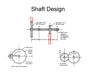
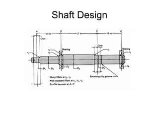
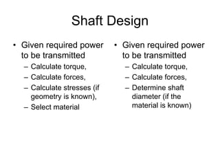
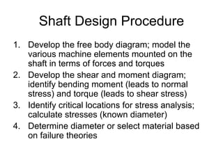
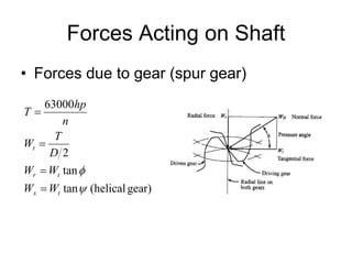


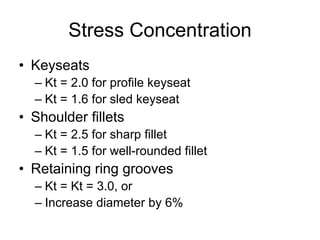


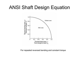

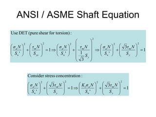
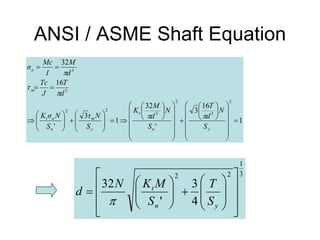


The document discusses shaft design and analysis. It provides information on forces acting on shafts, developing shear and moment diagrams, stress concentration factors, fatigue failure criteria, and the ANSI shaft design equation. An example is presented to demonstrate calculating torque and forces on a shaft, developing shear and moment diagrams, and determining the shaft diameter at critical locations using the design equation.


![Assignment [4] machining with solutions](https://cdn.slidesharecdn.com/ss_thumbnails/assignment4machining-withsolutions-121213110841-phpapp02-thumbnail.jpg?width=640&height=640&fit=bounds)