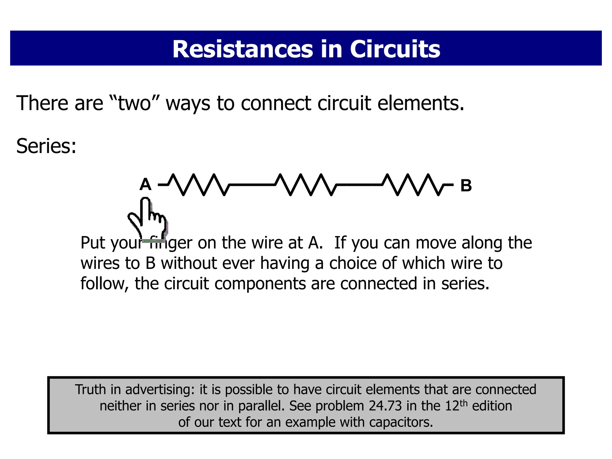
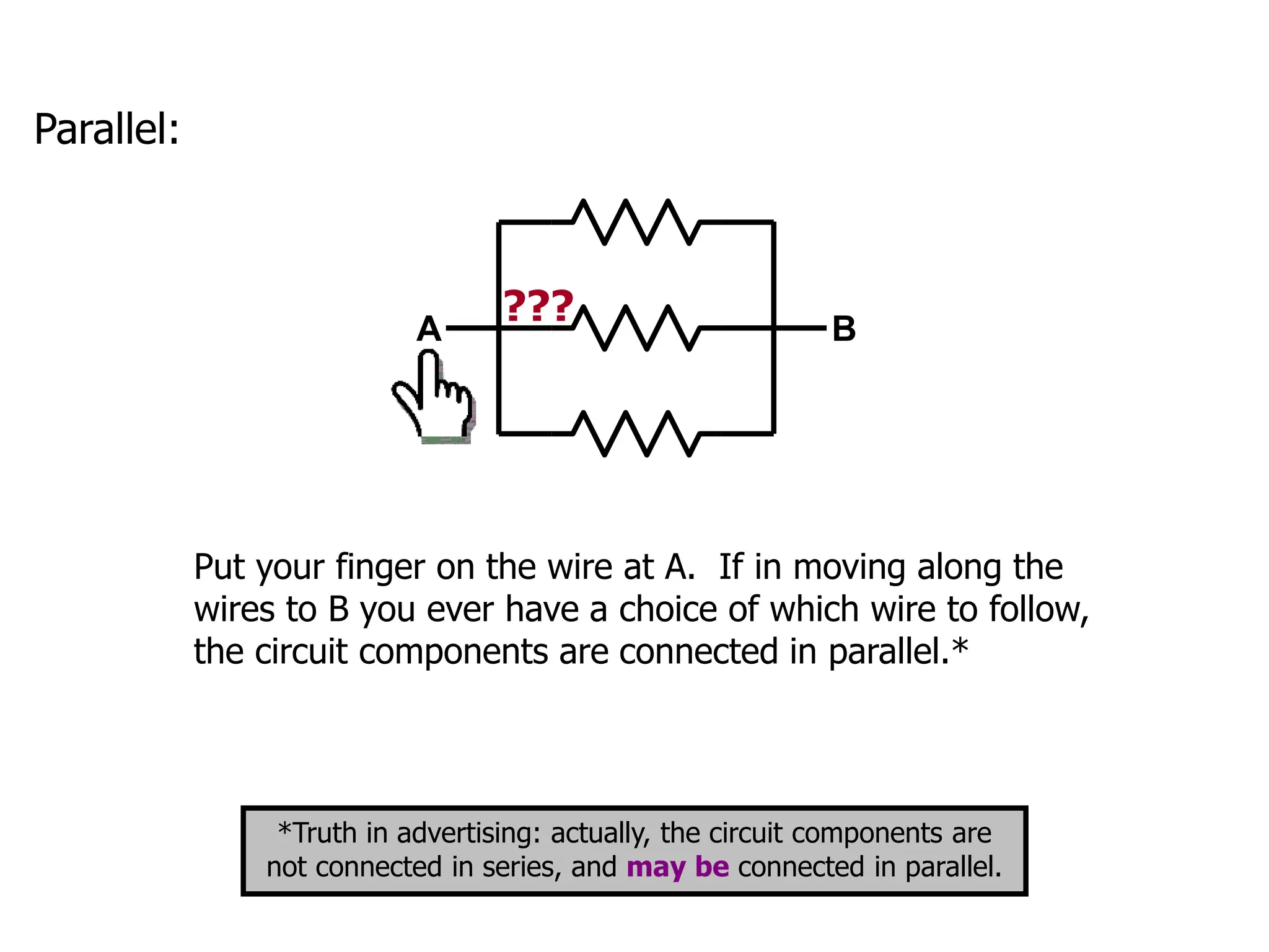
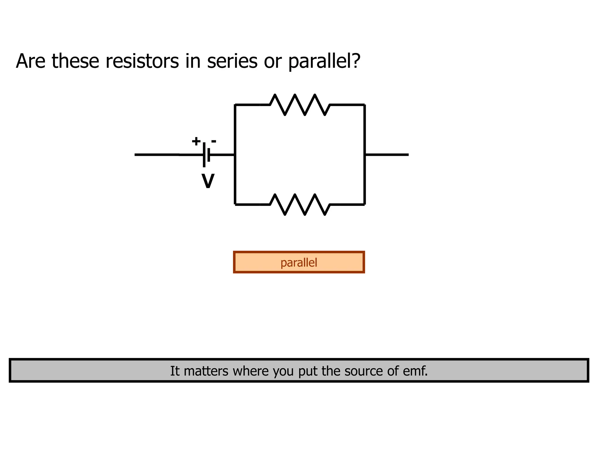
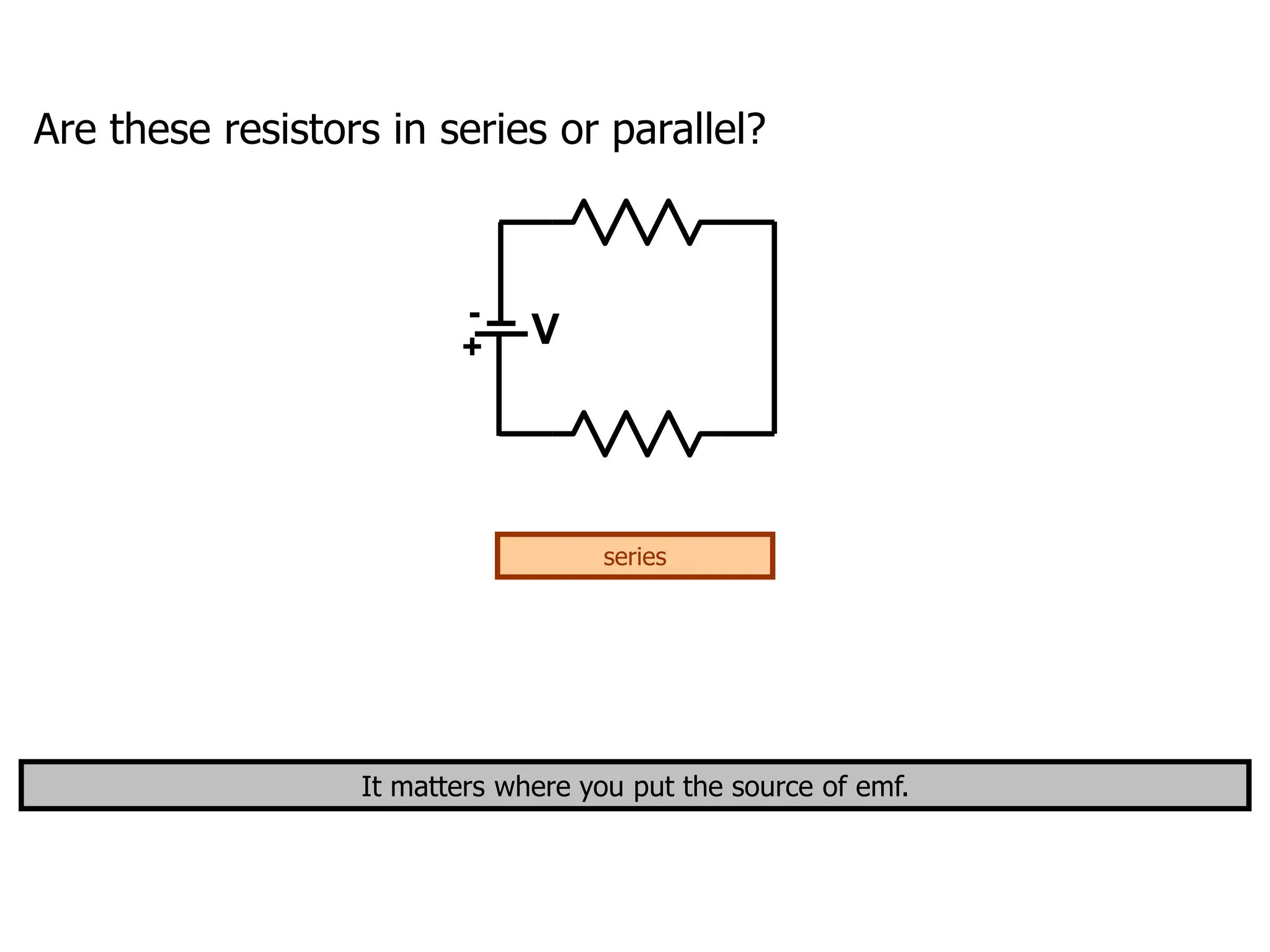
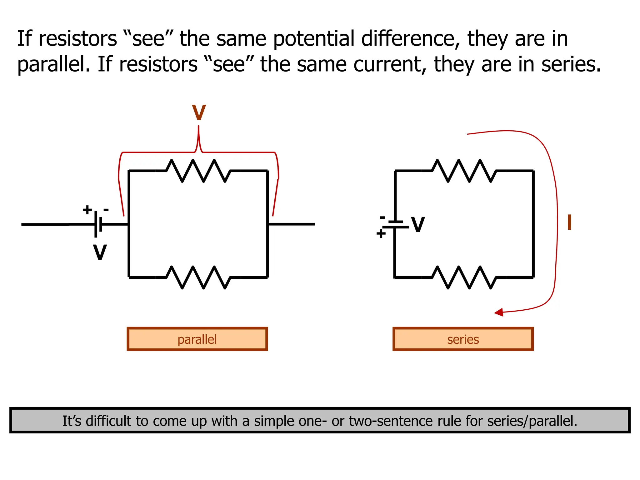
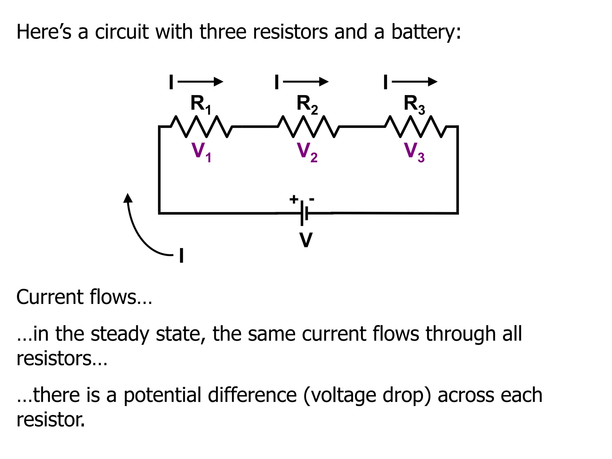
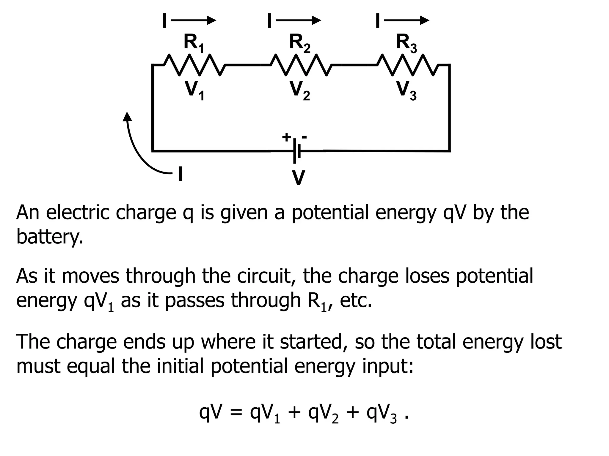
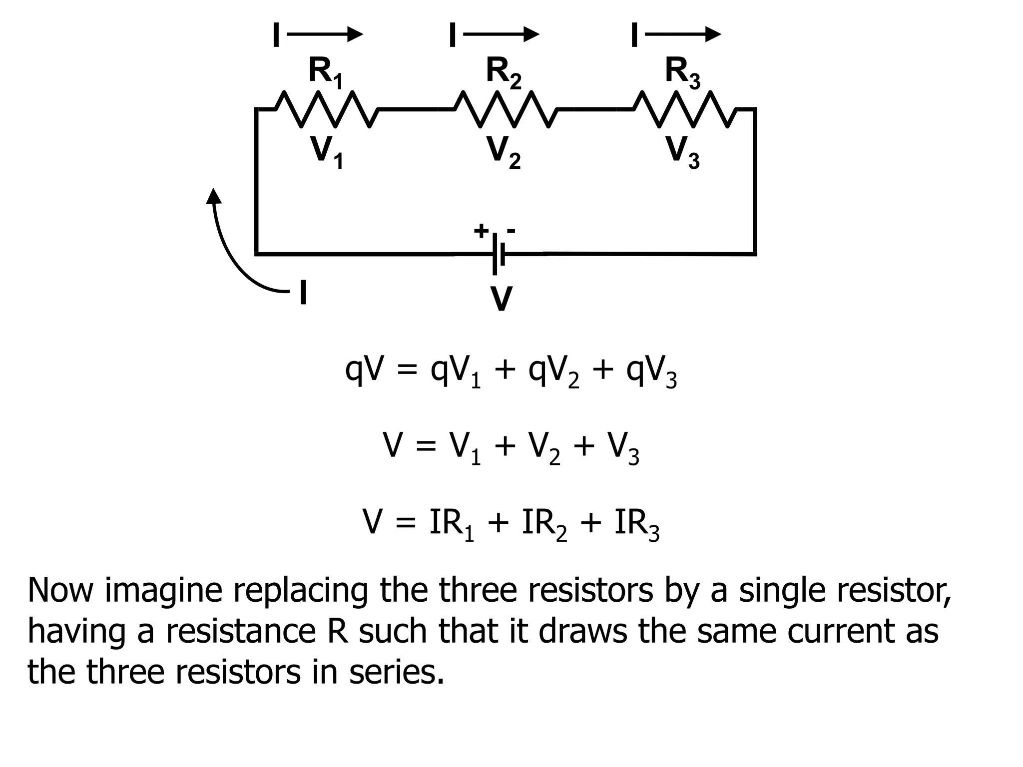
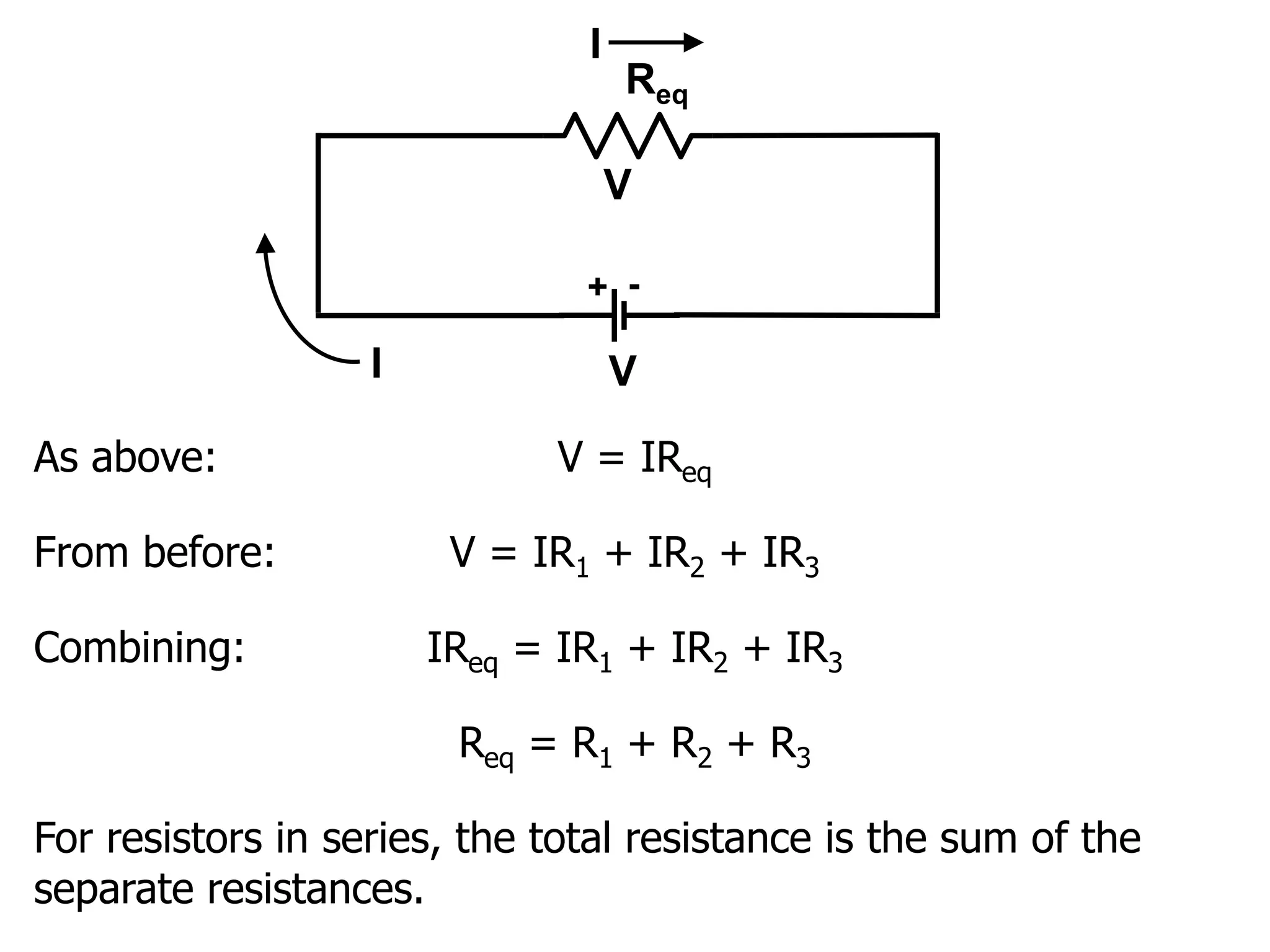
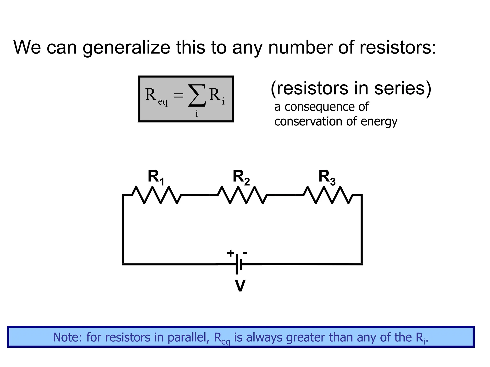
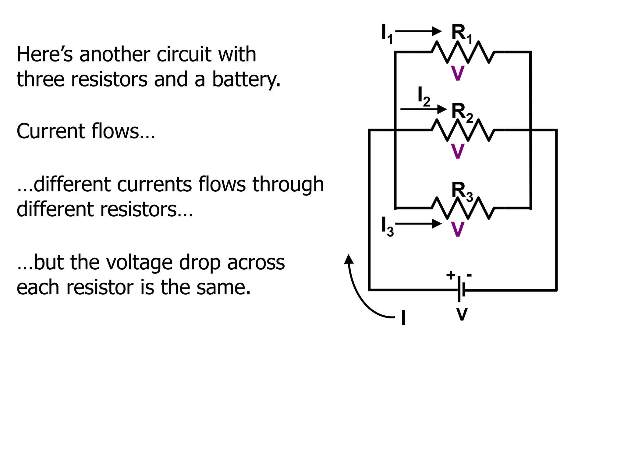
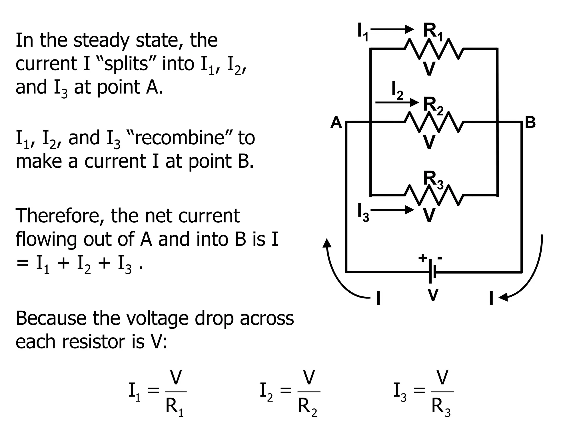
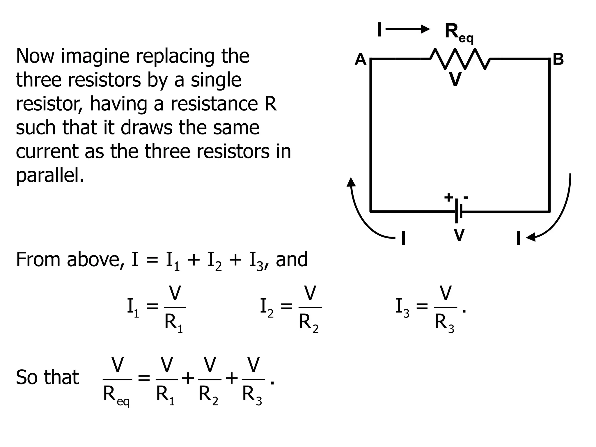
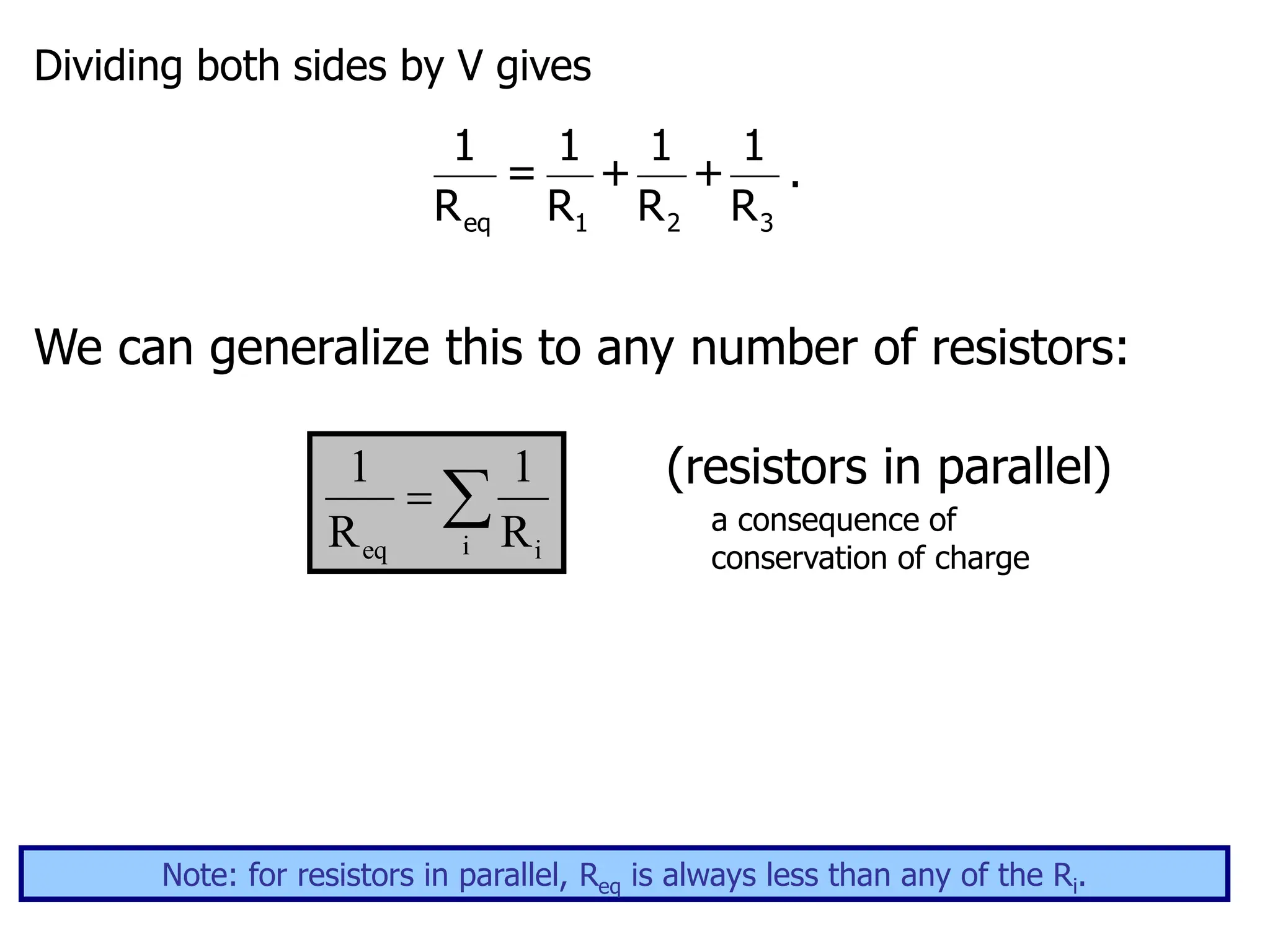
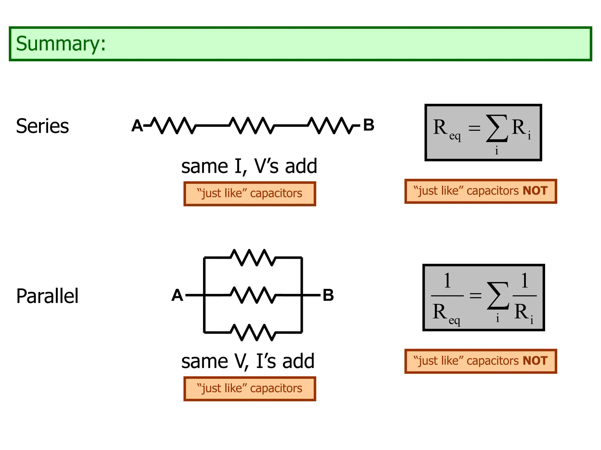
Today’s agenda:
Resistors in Series and Parallel.
You must be able to calculate currents and voltages in circuit components in series and in
parallel.
Kirchoff’s Rules.
You must be able to use Kirchoff’s Rules to calculate currents and voltages in circuit
components that are not simply in series or in parallel.
Resistances in Circuits
There are “two” ways to connect circuit elements.
Series:
A B
Put your finger on the wire at A. If you can move along the
wires to B without ever having a choice of which wire to
follow, the circuit components are connected in series.
Truth in advertising: it is possible to have circuit elements that are connected
neither in series nor in parallel. See problem 24.73 in the 12th edition
of our text for an example with capacitors.
Parallel:
A B
Put your finger on the wire at A. If in moving along the
wires to B you ever have a choice of which wire to follow,
the circuit components are connected in parallel.*
*Truth in advertising: actually, the circuit components are
not connected in series, and may be connected in parallel.
???
Are these resistors in series or parallel?
It matters where you put the source of emf.
+ -
V
parallel
Are these resistors in series or parallel?
It matters where you put the source of emf.
+
-
V
series
If resistors “see” the same potential difference, they are in
parallel. If resistors “see” the same current, they are in series.
It’s difficult to come up with a simple one- or two-sentence rule for series/parallel.
+
-
V
series
+ -
V
parallel
I
V
Here’s a circuit with three resistors and a battery:
R3
R2
R1
+ -
V
I
Current flows…
…in the steady state, the same current flows through all
resistors…
I
I
I
…there is a potential difference (voltage drop) across each
resistor.
V1 V3
V2
Applying conservation of energy allows us to calculate the
equivalent resistance of the series resistors.
I am including the derivation in these notes, for the benefit of
students who want to look at it.
In lecture, I will skip ahead past the derivation.
An electric charge q is given a potential energy qV by the
battery.
R3
R2
R1
+ -
V
I
I
I
I
V1 V3
V2
As it moves through the circuit, the charge loses potential
energy qV1 as it passes through R1, etc.
The charge ends up where it started, so the total energy lost
must equal the initial potential energy input:
qV = qV1 + qV2 + qV3 .
V = V1 + V2 + V3
V = IR1 + IR2 + IR3
Now imagine replacing the three resistors by a single resistor,
having a resistance R such that it draws the same current as
the three resistors in series.
R3
R2
R1
+ -
V
I
I
I
I
V1 V3
V2
qV = qV1 + qV2 + qV3
Req
+ -
V
I
V
I
As above: V = IReq
From before: V = IR1 + IR2 + IR3
Combining: IReq = IR1 + IR2 + IR3
Req = R1 + R2 + R3
For resistors in series, the total resistance is the sum of the
separate resistances.
We can generalize this to any number of resistors:
(resistors in series)
a consequence of
conservation of energy
R3
R2
R1
+ -
V
eq i
i
R R
 
Note: for resistors in parallel, Req is always greater than any of the Ri.
V
V
V
R3
R2
R1
+ -
V
I
Current flows…
…different currents flows through
different resistors…
…but the voltage drop across
each resistor is the same.
I3
I1
I2
Here’s another circuit with
three resistors and a battery.
Applying conservation of charge allows us to calculate the
equivalent resistance of the parallel resistors.
I am including the derivation in these notes, for the benefit of
students who want to look at it.
In lecture, I will skip ahead past the derivation.
V
V
V
R3
R2
R1
+ -
V
I
I3
I1
I2
A B
In the steady state, the
current I “splits” into I1, I2,
and I3 at point A.
I
I1, I2, and I3 “recombine” to
make a current I at point B.
Therefore, the net current
flowing out of A and into B is I
= I1 + I2 + I3 .
1 2 3
1 2 3
V V V
I = I = I =
R R R
Because the voltage drop across
each resistor is V:
Now imagine replacing the
three resistors by a single
resistor, having a resistance R
such that it draws the same
current as the three resistors in
parallel.
V
Req
+ -
V
I
I
A B
I
From above, I = I1 + I2 + I3, and
1 2 3
1 2 3
V V V
I = I = I = .
R R R
So that
eq 1 2 3
V V V V
= + + .
R R R R
Dividing both sides by V gives
eq 1 2 3
1 1 1 1
= + + .
R R R R
We can generalize this to any number of resistors:
(resistors in parallel)
a consequence of
conservation of charge
i
eq i
1 1
R R
 
Note: for resistors in parallel, Req is always less than any of the Ri.
Summary:
Series A B
eq i
i
R R
 
same I, V’s add
Parallel A B
same V, I’s add
i
eq i
1 1
R R
 
“just like” capacitors
“just like” capacitors NOT

lecture12_part_2_resistors_in_series_and_parallel.ppt

  • 1.
    Today’s agenda: Resistors inSeries and Parallel. You must be able to calculate currents and voltages in circuit components in series and in parallel. Kirchoff’s Rules. You must be able to use Kirchoff’s Rules to calculate currents and voltages in circuit components that are not simply in series or in parallel.
  • 2.
    Resistances in Circuits Thereare “two” ways to connect circuit elements. Series: A B Put your finger on the wire at A. If you can move along the wires to B without ever having a choice of which wire to follow, the circuit components are connected in series. Truth in advertising: it is possible to have circuit elements that are connected neither in series nor in parallel. See problem 24.73 in the 12th edition of our text for an example with capacitors.
  • 3.
    Parallel: A B Put yourfinger on the wire at A. If in moving along the wires to B you ever have a choice of which wire to follow, the circuit components are connected in parallel.* *Truth in advertising: actually, the circuit components are not connected in series, and may be connected in parallel. ???
  • 4.
    Are these resistorsin series or parallel? It matters where you put the source of emf. + - V parallel
  • 5.
    Are these resistorsin series or parallel? It matters where you put the source of emf. + - V series
  • 6.
    If resistors “see”the same potential difference, they are in parallel. If resistors “see” the same current, they are in series. It’s difficult to come up with a simple one- or two-sentence rule for series/parallel. + - V series + - V parallel I V
  • 7.
    Here’s a circuitwith three resistors and a battery: R3 R2 R1 + - V I Current flows… …in the steady state, the same current flows through all resistors… I I I …there is a potential difference (voltage drop) across each resistor. V1 V3 V2
  • 8.
    Applying conservation ofenergy allows us to calculate the equivalent resistance of the series resistors. I am including the derivation in these notes, for the benefit of students who want to look at it. In lecture, I will skip ahead past the derivation.
  • 9.
    An electric chargeq is given a potential energy qV by the battery. R3 R2 R1 + - V I I I I V1 V3 V2 As it moves through the circuit, the charge loses potential energy qV1 as it passes through R1, etc. The charge ends up where it started, so the total energy lost must equal the initial potential energy input: qV = qV1 + qV2 + qV3 .
  • 10.
    V = V1+ V2 + V3 V = IR1 + IR2 + IR3 Now imagine replacing the three resistors by a single resistor, having a resistance R such that it draws the same current as the three resistors in series. R3 R2 R1 + - V I I I I V1 V3 V2 qV = qV1 + qV2 + qV3
  • 11.
    Req + - V I V I As above:V = IReq From before: V = IR1 + IR2 + IR3 Combining: IReq = IR1 + IR2 + IR3 Req = R1 + R2 + R3 For resistors in series, the total resistance is the sum of the separate resistances.
  • 12.
    We can generalizethis to any number of resistors: (resistors in series) a consequence of conservation of energy R3 R2 R1 + - V eq i i R R   Note: for resistors in parallel, Req is always greater than any of the Ri.
  • 13.
    V V V R3 R2 R1 + - V I Current flows… …differentcurrents flows through different resistors… …but the voltage drop across each resistor is the same. I3 I1 I2 Here’s another circuit with three resistors and a battery.
  • 14.
    Applying conservation ofcharge allows us to calculate the equivalent resistance of the parallel resistors. I am including the derivation in these notes, for the benefit of students who want to look at it. In lecture, I will skip ahead past the derivation.
  • 15.
    V V V R3 R2 R1 + - V I I3 I1 I2 A B Inthe steady state, the current I “splits” into I1, I2, and I3 at point A. I I1, I2, and I3 “recombine” to make a current I at point B. Therefore, the net current flowing out of A and into B is I = I1 + I2 + I3 . 1 2 3 1 2 3 V V V I = I = I = R R R Because the voltage drop across each resistor is V:
  • 16.
    Now imagine replacingthe three resistors by a single resistor, having a resistance R such that it draws the same current as the three resistors in parallel. V Req + - V I I A B I From above, I = I1 + I2 + I3, and 1 2 3 1 2 3 V V V I = I = I = . R R R So that eq 1 2 3 V V V V = + + . R R R R
  • 17.
    Dividing both sidesby V gives eq 1 2 3 1 1 1 1 = + + . R R R R We can generalize this to any number of resistors: (resistors in parallel) a consequence of conservation of charge i eq i 1 1 R R   Note: for resistors in parallel, Req is always less than any of the Ri.
  • 18.
    Summary: Series A B eqi i R R   same I, V’s add Parallel A B same V, I’s add i eq i 1 1 R R   “just like” capacitors “just like” capacitors “just like” capacitors NOT “just like” capacitors NOT