
Recommended
Recommended
More Related Content
What's hot
What's hot (20)
Similar to Single phase transformer
Similar to Single phase transformer (20)
More from Jayaraju Gaddala
Recently uploaded
Recently uploaded (20)
Single phase transformer
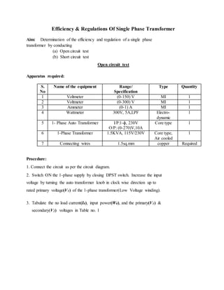
- 1. Efficiency & Regulations Of Single Phase Transformer Aim: Determination of the efficiency and regulation of a single phase transformer by conducting (a) Open circuit test (b) Short circuit test Open circuit test Apparatus required: S. No Name of the equipment Range/ Specification Type Quantity 1 Voltmeter (0-150) V MI 1 2 Voltmeter (0-300) V MI 1 3 Ammeter (0-1) A MI 1 4 Wattmeter 300V, 5A,LPF Electro- dynamic 1 5 1- Phase Auto Transformer I/P:1-ɸ, 230V O/P: (0-270)V,10A Core type 1 6 1-Phase Transformer 1.5KVA, 115V/230V Core type, Air cooled 1 7 Connecting wires 1.5sq.mm copper Required Procedure: 1. Connect the circuit as per the circuit diagram. 2. Switch ON the 1-phase supply by closing DPST switch. Increase the input voltage by turning the auto transformer knob in clock wise direction up to rated primary voltage(V1) of the 1-phase transformer(Low Voltage winding). 3. Tabulate the no load current(I0), input power(W0), and the primary(V1) & secondary(V2) voltages in Table no. 1
- 3. Tabular column: S.No Primary Voltage (V1) On L.V Side No load current (I0) Input Power (W0) Secondary Voltage (V2) On H.V Side Theoretical calculations: Iron losses, Wo = VoIo Cos Φo The no load shunt parameters are calculated from the OC test as The no load power factor, Cos Φo = Wo/VoIo The no load component currents are determined as Magnetizing component of no load current,Iµ = Io sin Φo Core loss component of no load current, Im = Io cos Φo I0= √ ( Iµ 2 + IW 2 ) Then, the magnetizing branch reactance, Xo= Vo / Iµ Resistance representing core loss, Ro = Vo / IW
- 4. W0 = V1 I0 Cos ɸ0 Watts Cos ɸ0 = W/ (V1 I0) Iµ = I0 Sin ɸ0 Amps IW = I0 Cos ɸ0 Amps X0 = V1/ Iµ Ohms R0 = V1/ IW Ohms Precautions: 1. All the connections should be tight. 2. Initially keep the output voltage of the autotransformer to zero.
- 5. a) Short circuit test Apparatus required: S.No Name of the equipment Range/ Specification Type Quantity 1 Voltmeter (0-30) V MI 1 2 Ammeter (0-10) A MI 1 3 Ammeter (0-20) A MI 1 4 Wattmeter 75V, 15A,UPF Electro- dynamic 1 5 1- Phase Auto- Transformer I/P: 1-ɸ, 230V O/P: (0-270)V,10A Core type 1 6 1-Phase Transformer 1.5KVA, 115V/230V Core type, Air cooled 1 7 Connecting wires 1.5sq.mm copper Required Procedure: 1. Connect the circuit as per the circuit Diagram. 2. Initially keep the output voltage of autotransformer at zero position. 3. Switch ON the circuit, Increase the output voltage of autotransformer slowly up to the rated current level of the primary and secondary windings of the 1- Phase transformer. 4. Note down the value of the input voltage (VSC) high voltage winding, input current on HV Side(I2), power(WSC) and the Current on LV Side (I1) in table. 5. Complete equivalent circuits of the transformer referred to both H.V. & L.V. side. 6. Efficiency of the Transformer at 25%, 50%, 75%, & 100% of the fullload current at unity p.f. 7. Full load regulation at power factor of (a) 1.0 (b) 0.8 lagging and (c) 0.8 leading. 8. A graph showing efficiency at unity p.f. against load current at rated voltage. 9. The maximum efficiency at the load (at unity p.f.) at which the maximum efficiency has occurred from the graph.
- 7. Tabular column: S.No Voltage (VSC) On H.V Side Current On H.V Side (I2) Input Power (WSC) Current (I1) On L.V Side Theoretical calculations: Wsc = Full load copper losses Form the test results we determine the series branch parameters of an equivalent circuit as Equivalent resistance referred to HV side, R01 = Wsc/ Isc 2 Equivalent impedance referred to HV side, Z01 = Vsc / Isc Equivalent leakage reactance referred to HV side, X01 = √ (Z01 2 – R01 2) And also short circuit power factor, Cos Φsc = Wsc/VscIsc The equivalent circuit obtained from this test is shown below.
- 8. Efficiency: Efficiency, η = 𝑃𝑜𝑤𝑒𝑟 𝑜𝑢𝑡𝑝𝑢𝑡 𝑖𝑛 𝐾𝑊 𝑃𝑜𝑤𝑒𝑟 𝑖𝑛𝑝𝑢𝑡 𝑖𝑛 𝐾𝑊 Efficiency, η = 𝑃𝑜𝑤𝑒𝑟 𝑜𝑢𝑡𝑝𝑢𝑡 𝑖𝑛 𝐾𝑊 (𝑃𝑜𝑤𝑒𝑟 𝑜𝑢𝑡𝑝𝑢𝑡 𝑖𝑛 𝐾𝑊 + 𝐶𝑜𝑝𝑝𝑒𝑟 𝑙𝑜𝑠𝑠 + 𝐶𝑜𝑟𝑒 𝑙𝑜𝑠𝑠) The core loss Pcore remains constant from no load to full load as the flux in the core remains constant. And the copper losses are depend on the square of the current. As the winding current varies from no load to full load, copper losses are also get varied. Consider that the KVA rating of the transformer is S, A fraction of the load is X and The power factor of the load is Cos Φ. Then The output power in KW = X S Cos Φ Suppose the copper loss at full load is Pcu (since X =1), Then copper loss at x per unit loading = X 2Pcu Therefore the efficiency of the transformer is Efficiency, η = (𝑋𝑆𝐶𝑜𝑠 𝛷) (𝑋𝑆𝐶𝑜𝑠 𝛷 + 𝑋2 𝑃𝑐𝑢 + 𝑃𝑐𝑜𝑟𝑒) In the above efficiency equation, the core or iron losses and full load copper losses are found by OC and SC tests. Table for efficiency at a fraction of the load and power factor: Cos Φ X 0.2 0.4 0.6 0.8 1
- 9. 1/4 1/2 3/4 Regulation: Percentage voltage regulation, %R = (𝐸2 – 𝑉2) 𝑉2 ∗100 The expression of voltage regulation in terms voltage drops is given asType equation here. %R = (𝐼1𝑅01 𝑐𝑜𝑠 𝛷 ± 𝐼1𝑋01 𝑠𝑖𝑛 𝛷) 𝑉1 ∗100 From the SC test data we can find out the regulation of a transformer. The positive sign is used for lagging power factor and negative sign is used for leading power factor Table for Regulation at a fraction of the load and power factor: Cos Φ X 0.2 0.4 0.6 0.8 1 1/4 1/2 3/4 Total Cu loss WSC = I1 2R01 Watts ` R01 = W/ I1 2 Ohms
- 10. Z01 = VSC/ I1 Ohms X01 = (Z01 2- R01 2) Ohms K= V2/V1; R02= R01.K2; X02= X01 .K2; Z02= Z01 .K2 Efficiency: Output/(Output+Losses) Regulation: as referred to primary (I1R01. Cos ɸ ± I1X01. Sin ɸ) ₓ 100 ; I1= kVA V1 V1 Upper sign (+) for lagging power factor and lower sign (-) for leading power factor Precautions: 1. All the connections should be tight. 2. Initially keep the output voltage of the autotransformer to zero. Result: