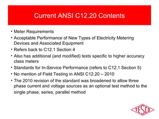
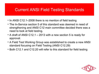
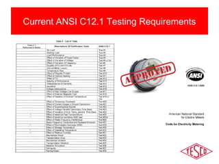
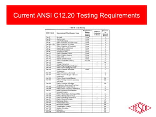
Understand contents of ANSI C12.20-2010 for 0.2 and 0.5 Accuracy Class Meters.
Understand the Relationship of C12.20 to C12.1.
Understand ANSI C12.20 Changes Planned for 2015. Edition and ANSI C12.1 changes planned for 2014.
Understand new ANSI C12.29 for Field Testing and potential time frame.
Discuss – Will this affect how we test in the field?
This presentation will give you better understanding of the contents of ANSI C12.20-2010 for 0.2 and 0.5 Accuracy Class Meters. You will also understand the Relationship of C12.20 to C12.1, understand ANSI C12.20 Changes Planned for 2015 Edition and ANSI C12.1 changes planned for 2014, & understand the new ANSI C12.29 for Field Testing and potential time frame.
Discuss – Will this affect how we test in the field?
Presented at the Southeastern Electricity Metering Association (SEMA). 11/2013
Manage change and minimize risk of AMI Meter Certification throughout the process of deployment. Topics covered include: initial certification testing and First Article Testing; Developing functional testing from initial certification protocols; the need for continued certification training on a regular basis; and protocols and frequency for certification testing during and after deployment.
Learn about The PHMSA Hazardous Liquid Pipelines Mega Rule Part (1) revisions and new requirements. Discover what the new rule means for pipeline operators.
This presentation highlights ANSI (American National STandard Institute, Inc.) standards and recent updates that affect metering, including code for electricity metering, new meter forms and more.
Learn about The PHMSA Hazardous Liquid Pipelines Mega Rule Part (1) revisions and new requirements. Discover what the new rule means for pipeline operators.
This presentation gives insight into the American National Standard Institute, Inc. (ANSI) and specifically the C12.1 group of standards for electric metering. Also discussed is the law in New York State for all things metering in NY State PSC Part 92. This presentation was given at the MEUA Meter School. 03.04.20
This presentation covers the basics of meter testing including: why we test; how to test; types of meter tests; how utility tests differ from customer request tests; in-service testing; and what to do with the test data. 06/26/2019
Discuss and gain an understanding about;
What is ANSI C12.1 and why do we care
What is suitable traceability according to the law
The need for Meter Standards and traceability in electric metering
The definition of metrology and the application of this science in electric metering
The difference between accuracy and precision and why both are important
The use of Standards in the test lab
The use of portable Standards in the field
Calibration of the measuring instrument is the process in which the readings obtained from the instrument are compared with the sub-standards in the laboratory at several points along the scale of the instrument. As per the results obtained from the readings obtained of the instrument and the sub-standards, the curve is plotted. If the instrument is accurate there will be matching of the scales of the instrument and the sub-standard. If there is deviation of the measured value from the instrument against the standard value, the instrument is calibrated to give the correct values.
All the new instruments have to be calibrated against some standard in the very beginning. For the new instrument the scale is marked as per the sub-standards available in the laboratories, which are meant especially for this purpose. After continuous use of the instrument for long periods of time, sometimes it loses its calibration or the scale gets distorted, in such cases the instrument can be calibrated again if it is in good reusable condition.
Even if the instruments in the factory are working in the good condition, it is always advisable to calibrate them from time-to-time to avoid wrong readings of highly critical parameters. This is very important especially in the companies where very high precision jobs are manufactured with high accuracy.
All the measuring instruments for measurement of length, pressure, temperature etc should be calibrated against some standard scale at the regular intervals as specified by the manufacturer. There are different methods or techniques of calibration, which are applied depending on whether it is routine calibration or if it is for special purpose where highly accurate calibration of the instruments is desired. In many cases different methods of calibration are applied for all the individual instruments. No what type of calibrations is being done, all of them are done in the laboratory.
The calibration of the instrument is done in the laboratory against the sub-standard instruments, which are used very rarely for this sole purpose. These sub-standards are kept in highly controlled air-conditioned atmosphere so that there their scale does not change with the external atmospheric changes.
To maintain the accuracy of the sub-standards, they are checked periodically against some standard which is kept in the metrological laboratories under highly secured, safe, clean and air conditioned atmosphere. Finally, standards can be checked against the absolute measurements of the quantity, which the instruments are designed to measure.
Difference Between Quality Control Inspection and Commissioning InspectionOlivia Wilson
Commissioning is a complex process but it's an important process in the transition from construction to the commissioning phase. This is where the documents for QC (Quality Control) and Commissioning Inspections come in. Find here more about these inspections and types: https://www.global-cxm.com/commissioning/
ASME Code and Quality assurance for construction of nuclear facilitiesASME Co...Mark Mitchell
ASME Code and Quality assurance for construction of nuclear facilities
Mark N. Mitchell
Principal Engineer at Bufo Technology and
Member BPV Committee on Construction of Nuclear Facility Components (BPV III)
Nuclear Africa 2011
Hot Sockets are not a new phenomenon. Virtually every meter man has pulled a meter with a portion of the meter base around a blade melted and virtually every utility has been called to assist in the investigation of a fire at a meter box.
AMI deployments, because of the volume of meters involved put a spot light on this issue.
What causes a hot socket?
Are the meters ever the cause of a meter box failure?
What are the things to look for when inspecting an existing meter installation?
What are the best practices for handling potential hot sockets?
This presentation will cover the results of our lab investigation into the sources for hot sockets, the development of a fixture to simulate hot sockets, the tests and data gleaned from hot sockets, and a discussion of “best practices” regarding hot sockets.
Learn about The PHMSA Hazardous Liquid Pipelines Mega Rule Part (1) revisions and new requirements. Discover what the new rule means for pipeline operators.
This presentation highlights ANSI (American National STandard Institute, Inc.) standards and recent updates that affect metering, including code for electricity metering, new meter forms and more.
Learn about The PHMSA Hazardous Liquid Pipelines Mega Rule Part (1) revisions and new requirements. Discover what the new rule means for pipeline operators.
This presentation gives insight into the American National Standard Institute, Inc. (ANSI) and specifically the C12.1 group of standards for electric metering. Also discussed is the law in New York State for all things metering in NY State PSC Part 92. This presentation was given at the MEUA Meter School. 03.04.20
This presentation covers the basics of meter testing including: why we test; how to test; types of meter tests; how utility tests differ from customer request tests; in-service testing; and what to do with the test data. 06/26/2019
Discuss and gain an understanding about;
What is ANSI C12.1 and why do we care
What is suitable traceability according to the law
The need for Meter Standards and traceability in electric metering
The definition of metrology and the application of this science in electric metering
The difference between accuracy and precision and why both are important
The use of Standards in the test lab
The use of portable Standards in the field
Calibration of the measuring instrument is the process in which the readings obtained from the instrument are compared with the sub-standards in the laboratory at several points along the scale of the instrument. As per the results obtained from the readings obtained of the instrument and the sub-standards, the curve is plotted. If the instrument is accurate there will be matching of the scales of the instrument and the sub-standard. If there is deviation of the measured value from the instrument against the standard value, the instrument is calibrated to give the correct values.
All the new instruments have to be calibrated against some standard in the very beginning. For the new instrument the scale is marked as per the sub-standards available in the laboratories, which are meant especially for this purpose. After continuous use of the instrument for long periods of time, sometimes it loses its calibration or the scale gets distorted, in such cases the instrument can be calibrated again if it is in good reusable condition.
Even if the instruments in the factory are working in the good condition, it is always advisable to calibrate them from time-to-time to avoid wrong readings of highly critical parameters. This is very important especially in the companies where very high precision jobs are manufactured with high accuracy.
All the measuring instruments for measurement of length, pressure, temperature etc should be calibrated against some standard scale at the regular intervals as specified by the manufacturer. There are different methods or techniques of calibration, which are applied depending on whether it is routine calibration or if it is for special purpose where highly accurate calibration of the instruments is desired. In many cases different methods of calibration are applied for all the individual instruments. No what type of calibrations is being done, all of them are done in the laboratory.
The calibration of the instrument is done in the laboratory against the sub-standard instruments, which are used very rarely for this sole purpose. These sub-standards are kept in highly controlled air-conditioned atmosphere so that there their scale does not change with the external atmospheric changes.
To maintain the accuracy of the sub-standards, they are checked periodically against some standard which is kept in the metrological laboratories under highly secured, safe, clean and air conditioned atmosphere. Finally, standards can be checked against the absolute measurements of the quantity, which the instruments are designed to measure.
Difference Between Quality Control Inspection and Commissioning InspectionOlivia Wilson
Commissioning is a complex process but it's an important process in the transition from construction to the commissioning phase. This is where the documents for QC (Quality Control) and Commissioning Inspections come in. Find here more about these inspections and types: https://www.global-cxm.com/commissioning/
ASME Code and Quality assurance for construction of nuclear facilitiesASME Co...Mark Mitchell
ASME Code and Quality assurance for construction of nuclear facilities
Mark N. Mitchell
Principal Engineer at Bufo Technology and
Member BPV Committee on Construction of Nuclear Facility Components (BPV III)
Nuclear Africa 2011
Hot Sockets are not a new phenomenon. Virtually every meter man has pulled a meter with a portion of the meter base around a blade melted and virtually every utility has been called to assist in the investigation of a fire at a meter box.
AMI deployments, because of the volume of meters involved put a spot light on this issue.
What causes a hot socket?
Are the meters ever the cause of a meter box failure?
What are the things to look for when inspecting an existing meter installation?
What are the best practices for handling potential hot sockets?
This presentation will cover the results of our lab investigation into the sources for hot sockets, the development of a fixture to simulate hot sockets, the tests and data gleaned from hot sockets, and a discussion of “best practices” regarding hot sockets.
Throughout this presentation you will learn to understand customer concerns about Smart Meters and AMI meters. You will also be able to respond as a Utility and as a Utility Worker.
Highlights of the new value proposition for metering personnel at their respective utility companies in a post-AMI world. Examples of issues which have arisen or been identified over the course of various deployments and in the immediate aftermath of an AMI deployment.
Discuss the differences between functional and accuracy testing
Discuss the types of functional testing required in a post-AMI world
Discuss the need for functional testing as well as Certification or FAT testing (first article testing)
Customers always have the right to request a meter test.
Some utilities and some jurisdictions allow for testing at the customer site, others require a test in a laboratory environment.
Some allow the customer to witness the test and others require the utility commission to witness the test.
Utilities must show that the meter tests well and must demonstrate that they have a test program in place to ensure the meters in service are performing well.
This presentation will demonstrate:
Why do we test?
How do we test?
What types of meter tests are there?
How do utility tests differ from customer request tests?
What is In-Service Testing?
How do we know meter tests are good?
What do we do with the test data?
This presentation will go through the history of the electric meter, dating back to 1802 and noting significant visionaries who helped play a part in the evolution of the meter as we see it today.
As many utilities have elected to deploy advanced metering systems and millions of new solid-state, microprocessor based end-points with communications under glass, there has been a dramatic shift in the approach to qualifying and certifying electricity meters.
This presentation will highlight the need for a rigorous approach to meter certification as well as continued testing as both the meter and the communication module and the firmware to run both are upgraded and changed over the course of deployment.
Examples of issues which have arisen over the course of various deployments along with varying approaches to and interpretations of the same ANSI tests by manufacturers will be discussed.
Presented at the Southeastern Electricity Metering Association (SEMA). 11/2013
As many utilities have elected to deploy advanced metering systems and millions of new solid-state, microprocessor based end-points with communications under glass, a dramatic shift has begun regarding where metering resources are being deployed and what they are doing.
This presentation will highlight the new value proposition for metering personnel at their respective utility companies in this AMI dominated World.
Examples of issues which have arisen or been identified over the course of various deployments and in the immediate aftermath of an AMI deployment.
This presentation will give you an understanding of self contained and transformer rated current transformers. You will also discuss meter testing, CT testing, ratio & burden testing.
TESCO has been involved with metering for more than 100 years. Our focus has always been on the needs of metering, with a wide range of software, test equipment, and tools.
Meter Manager is the result of more than 20 years of experience creating software for electric and gas utilities. Meter Manager has been designed from the ground up to meet your needs not only today, but in the future as well. It is built with state-of-art tools and modern software architecture. Our software continues to grow, with new and expanded features, all of which are made available to all of our customers.
Over much of the 20th century, utilities, regulators and customers each relied upon lab and field meter testing efforts which were primarily focused upon the accuracy of the watt-hour meter and demand register.
This focus is now changing with overwhelming deployment of electronic meters and significant deployment of AMR and AMI meters throughout the installed base in North America.
The focus has now shifted to the metering installation as a whole and not the accuracy of the meter.
This presentation is an overview of the ANSI C12 Standards that pertain to electric metering. This presentation was given at the PREA Meter School in March 2022.
This presentation is an overview of the ANSI C12 Standards that pertain to electric metering. This presentation was given at the PREA Meter School. 03/10/20.
This presentation was given at MEUA Meter School and gives attendees an introduction to meter testing. Topics covered include: why do we test; how do we test; field testing; complaint testing; general meter testing requirements; new meter testing programs; return to service testing; in-service testing; statistical test plans; tracking meter records, and more! 03/03.20
Given by SAMSCO's John Kretzschmar, this presentation covers the basics of meter testing including: why we test; how to test; types of meter tests; how utility tests differ from customer request tests; in-service testing; and what to do with the test data.
As many utilities have elected to deploy advanced metering systems and millions of new solid-state, microprocessor based end-points with communications under glass, a dramatic shift has begun regarding where metering resources are being deployed and what they are doing.This presentation will highlight the new value proposition for metering personnel at their respective utility companies in a post-AMI World.
Examples of issues which have arisen or been identified over the course of various deployments and in the immediate aftermath of an AMI deployment.
This presentation covers the basics of meter testing including: why we test; how to test; types of meter tests; how utility tests differ from customer request tests; in-service testing; and what to do with the test data.
This presentation covers the basics of meter testing including why we test; how to test; types of meter tests; how utility tests differ from customer request tests; in-service testing; and what to do with the test data—presented at NC Meter School 2022.
Understand types of meter testing
Review categories of meter testing
Review test plans for meters
review state meter testing requirements
Review why statistical test plans are the best
Review changes for ANSI testing requiements
Review aspects of traceability of meter test results
A review of the different types of meter testing, test plans, ANSI requirements, and the aspects of traceability of meter test results. Presented at the ECNE Fall Conference. 10/9/2013
This presentation explains why we test, types of tests and requirements, and data tracking. It's anything and everything you wanted to know about meter testing!
GraphRAG is All You need? LLM & Knowledge GraphGuy Korland
Guy Korland, CEO and Co-founder of FalkorDB, will review two articles on the integration of language models with knowledge graphs.
1. Unifying Large Language Models and Knowledge Graphs: A Roadmap.
https://arxiv.org/abs/2306.08302
2. Microsoft Research's GraphRAG paper and a review paper on various uses of knowledge graphs:
https://www.microsoft.com/en-us/research/blog/graphrag-unlocking-llm-discovery-on-narrative-private-data/
Search and Society: Reimagining Information Access for Radical FuturesBhaskar Mitra
The field of Information retrieval (IR) is currently undergoing a transformative shift, at least partly due to the emerging applications of generative AI to information access. In this talk, we will deliberate on the sociotechnical implications of generative AI for information access. We will argue that there is both a critical necessity and an exciting opportunity for the IR community to re-center our research agendas on societal needs while dismantling the artificial separation between the work on fairness, accountability, transparency, and ethics in IR and the rest of IR research. Instead of adopting a reactionary strategy of trying to mitigate potential social harms from emerging technologies, the community should aim to proactively set the research agenda for the kinds of systems we should build inspired by diverse explicitly stated sociotechnical imaginaries. The sociotechnical imaginaries that underpin the design and development of information access technologies needs to be explicitly articulated, and we need to develop theories of change in context of these diverse perspectives. Our guiding future imaginaries must be informed by other academic fields, such as democratic theory and critical theory, and should be co-developed with social science scholars, legal scholars, civil rights and social justice activists, and artists, among others.
Essentials of Automations: Optimizing FME Workflows with ParametersSafe Software
Are you looking to streamline your workflows and boost your projects’ efficiency? Do you find yourself searching for ways to add flexibility and control over your FME workflows? If so, you’re in the right place.
Join us for an insightful dive into the world of FME parameters, a critical element in optimizing workflow efficiency. This webinar marks the beginning of our three-part “Essentials of Automation” series. This first webinar is designed to equip you with the knowledge and skills to utilize parameters effectively: enhancing the flexibility, maintainability, and user control of your FME projects.
Here’s what you’ll gain:
- Essentials of FME Parameters: Understand the pivotal role of parameters, including Reader/Writer, Transformer, User, and FME Flow categories. Discover how they are the key to unlocking automation and optimization within your workflows.
- Practical Applications in FME Form: Delve into key user parameter types including choice, connections, and file URLs. Allow users to control how a workflow runs, making your workflows more reusable. Learn to import values and deliver the best user experience for your workflows while enhancing accuracy.
- Optimization Strategies in FME Flow: Explore the creation and strategic deployment of parameters in FME Flow, including the use of deployment and geometry parameters, to maximize workflow efficiency.
- Pro Tips for Success: Gain insights on parameterizing connections and leveraging new features like Conditional Visibility for clarity and simplicity.
We’ll wrap up with a glimpse into future webinars, followed by a Q&A session to address your specific questions surrounding this topic.
Don’t miss this opportunity to elevate your FME expertise and drive your projects to new heights of efficiency.
Kubernetes & AI - Beauty and the Beast !?! @KCD Istanbul 2024Tobias Schneck
As AI technology is pushing into IT I was wondering myself, as an “infrastructure container kubernetes guy”, how get this fancy AI technology get managed from an infrastructure operational view? Is it possible to apply our lovely cloud native principals as well? What benefit’s both technologies could bring to each other?
Let me take this questions and provide you a short journey through existing deployment models and use cases for AI software. On practical examples, we discuss what cloud/on-premise strategy we may need for applying it to our own infrastructure to get it to work from an enterprise perspective. I want to give an overview about infrastructure requirements and technologies, what could be beneficial or limiting your AI use cases in an enterprise environment. An interactive Demo will give you some insides, what approaches I got already working for real.
Slack (or Teams) Automation for Bonterra Impact Management (fka Social Soluti...Jeffrey Haguewood
Sidekick Solutions uses Bonterra Impact Management (fka Social Solutions Apricot) and automation solutions to integrate data for business workflows.
We believe integration and automation are essential to user experience and the promise of efficient work through technology. Automation is the critical ingredient to realizing that full vision. We develop integration products and services for Bonterra Case Management software to support the deployment of automations for a variety of use cases.
This video focuses on the notifications, alerts, and approval requests using Slack for Bonterra Impact Management. The solutions covered in this webinar can also be deployed for Microsoft Teams.
Interested in deploying notification automations for Bonterra Impact Management? Contact us at sales@sidekicksolutionsllc.com to discuss next steps.
Dev Dives: Train smarter, not harder – active learning and UiPath LLMs for do...UiPathCommunity
💥 Speed, accuracy, and scaling – discover the superpowers of GenAI in action with UiPath Document Understanding and Communications Mining™:
See how to accelerate model training and optimize model performance with active learning
Learn about the latest enhancements to out-of-the-box document processing – with little to no training required
Get an exclusive demo of the new family of UiPath LLMs – GenAI models specialized for processing different types of documents and messages
This is a hands-on session specifically designed for automation developers and AI enthusiasts seeking to enhance their knowledge in leveraging the latest intelligent document processing capabilities offered by UiPath.
Speakers:
👨🏫 Andras Palfi, Senior Product Manager, UiPath
👩🏫 Lenka Dulovicova, Product Program Manager, UiPath
Builder.ai Founder Sachin Dev Duggal's Strategic Approach to Create an Innova...Ramesh Iyer
In today's fast-changing business world, Companies that adapt and embrace new ideas often need help to keep up with the competition. However, fostering a culture of innovation takes much work. It takes vision, leadership and willingness to take risks in the right proportion. Sachin Dev Duggal, co-founder of Builder.ai, has perfected the art of this balance, creating a company culture where creativity and growth are nurtured at each stage.
Smart TV Buyer Insights Survey 2024 by 91mobiles.pdf91mobiles
91mobiles recently conducted a Smart TV Buyer Insights Survey in which we asked over 3,000 respondents about the TV they own, aspects they look at on a new TV, and their TV buying preferences.
UiPath Test Automation using UiPath Test Suite series, part 4DianaGray10
Welcome to UiPath Test Automation using UiPath Test Suite series part 4. In this session, we will cover Test Manager overview along with SAP heatmap.
The UiPath Test Manager overview with SAP heatmap webinar offers a concise yet comprehensive exploration of the role of a Test Manager within SAP environments, coupled with the utilization of heatmaps for effective testing strategies.
Participants will gain insights into the responsibilities, challenges, and best practices associated with test management in SAP projects. Additionally, the webinar delves into the significance of heatmaps as a visual aid for identifying testing priorities, areas of risk, and resource allocation within SAP landscapes. Through this session, attendees can expect to enhance their understanding of test management principles while learning practical approaches to optimize testing processes in SAP environments using heatmap visualization techniques
What will you get from this session?
1. Insights into SAP testing best practices
2. Heatmap utilization for testing
3. Optimization of testing processes
4. Demo
Topics covered:
Execution from the test manager
Orchestrator execution result
Defect reporting
SAP heatmap example with demo
Speaker:
Deepak Rai, Automation Practice Lead, Boundaryless Group and UiPath MVP
1. ANSI Testing
Proposed Changes
to ANSI C12
Prepared by Tom Lawton, TESCO
10/02/2012 Slide 1
The Eastern Specialty Company
for the ECNE Fall E&O 2014 Conference
2. Session Objectives
• Understand contents of ANSI C12.20-2010 for 0.2 and 0.5
Accuracy Class Meters
• Understand the Relationship of C12.20 to C12.1
• Understand ANSI C12.20 Changes Planned for 2015 Edition
and ANSI C12.1 changes planned for 2014
• Understand new ANSI C12.29 for Field Testing and potential
time frame
• Discuss – Will this affect how we test in the field?
3. Current Meter Testing Standards
Meter Testing for new and in-service kilowatt-hour meters, both
electronic and electromechanical is specified in ANSI C12.1-2008,
American National Standard for Electric Meters, Code for Electricity
Metering. Most utility commissions use this Standard as a
reference or the basis for their meter testing requirements.
ANSI C12.20-2010, American National Standard for Electricity
Meters, 0.2 and 0.5 Accuracy Classes, provides different test
tolerances and a few different or modified tests for higher accuracy
meters. There is no reference made in C12.20 to field testing. The
only mention of in-service testing refers back to Section 5 of C12.1
.
4. Current ANSI C12.20 Requirements
• ANSI C12.20 establishes aspects
and acceptable performance criteria
for 0.2 and 0.5 percent accuracy
class meters meeting Blondel’s
Theorem. This means that C12.20 is
not applicable for 2S meters.
• Where there are differences between
C12.20 and C12.1, ANSI Standard
C12.20 takes precedence.
5. Current ANSI C12.20 Contents
• Meter Requirements
• Acceptable Performance of New Types of Electricity Metering
Devices and Associated Equipment
• Refers back to C12.1 Section 4
• Also has additional (and modified) tests specific to higher accuracy
class meters
• Standards for In-Service Performance (refers to C12.1 Section 5)
• No mention of Field Testing in ANSI C12.20 – 2010
• The 2010 revision of the standard was broadened to allow three
phase current and voltage sources as an optional test method to the
single phase, series, parallel method
6. Current ANSI Field Testing Standards
• In ANSI C12.1–2008 there is no mention of field testing
• The In-Service section 5 of this standard was deemed in need of
strengthening and ANSI C12 main committee decided there was a
need to look at field testing.
• A draft of ANSI C12.1 – 2013 with a new section 5 is ready for
approval.
• A Field Test Working Group was established to create a new ANSI
standard focusing on Field Testing (ANSI C12.29)
• Both C12.1 and C12.20 will refer to this standard for field testing
9. Current Meter Testing to Standards
• Many State Utility Commissions require that new higher accuracy class
electric meters meet ANSI C12.1 and C12.20 requirements.
• New meters are tested using all or a group of tests specified in ANSI C12.1
and C12.20. These tests are typically performed by the meter vendors.
• Meter vendors have different interpretations of certain ANSI tests and even
what “ANSI qualified” means.
• Meter vendors often perform ANSI testing early in the development of a
meter and certify future modifications to the meter by stating the updated
design is similar to the old design in form and function.
10. ANSI C12.1 – 2013 Section 5
Proposed Changes
• More options for statistical models to use
• More options for what to do if a group starts to perform poorly
• Addresses the type of statistical testing available for ancillary devices (e.g.
disconnect switches; communication devices).
• Addresses the need to use statistical methods to determine as far in
advance as possible the potential failure modes and life expectancies of any
new technology being deployed to the field.
11. What do These Changes Mean for
Field Testing
• The revised Section 5 for ANSI C12.1 will not specify any new field tests. The in-service
testing required can be done in the field or in the meter shop as long as the
basic requirements of the tests are met.
• The revised Section 5 tries to include ancillary devices including disconnect switches
included with the meter and external CT’s and PT’s.
• This portion of the Standard focuses on the performance of the device as a group and
not the specfics of the test being performed.
• ANSI C12 Main Committee has decided that this aspect of testing has been
overlooked and has created a working group to address the “how-to” of field testing.
A new standard, ANSI C12.29 is anticipated to be be drafted by this working group
and presented to the main committee of C12 for approval.
• This working group has no time table to complete their work, but they are hoping to
have a draft ready for the Spring 2014 ANSI meeting (The main committee meets
every 6 months in conjunction with the EEI TD&M conference.
12. New ANSI C12.29 for Field Testing
Metering Devices
ANSI C12.29 will establish recommended
field testing for metering devices and should
eventually be referenced in C12.1 and C12.20.
The new standard is expected to have three
Sections:
• Meter Testing
• Instrument Transformer Testing
• Site Wiring and Auxiliary Devices
13. New ANSI C12.29 for Field Testing
Metering Devices
Meter Testing will be divided into three
categories based on where current and
voltage is supplied…
• Using Customer Potential with Current
Supplied by the Test Equipment
• Using Customer Potential and
Customer Supplied Current
• Using Potential and Current Supplied
by Test Equipment
14. New ANSI C12.29 for Field Testing
Metering Devices
Instrument Transformer testing is anticipated to focus on:
• Burden Testing - The theory and practical
application in the field
• Ratio Testing - Practical application in the
field
• Visual inspection of the CT’s and PT’s
15. New ANSI C12.29 for Field Testing
Metering Devices
Site Wiring and Auxiliary devices is
anticipated to focus on:
• Visual inspection
• Continuity testing
• Service Ground testing
• Communication testing
• Disconnect testing
• Additional device testing
16. New ANSI C12.29 for Field Testing
Metering Devices
What the new Standard is not expected to
do:
• Mandate a new test or tests
• Mandate the “right way” to do this test
• Mandate the use of any equipment or
specific processes
This Standard is anticipated to be a “Best
Practices” type of document and not a
new set of requirements for Utility
Metering Groups
17. New ANSI C12.29 for Field Testing
Metering Devices
Given the early stages for this Working Group
this is all personal opinion and could change
before the new Standard is completed.
There is also no mandate that this Standard
ever has to come into existence. If the
Committee never presents a draft or if the
ANSI C12 main committee rejects the draft
there will be no C12.9 in the near future, and
if approved, C12.1 and C12.20 do not have
to reference the new Standard
18. Site Verification…
The New Field Testing
Where are ANSI and the voting members heading?
Toward more comprehensive field testing that focuses on far more than just
accuracy testing. The members vision for the future of field testing is that utilities
will perform the following checks when checking a metering installation in the field
• Meter Accuracy testing
• Meter Communications Performance
• Software and firmware verification
• Setting verification
• Functional testing
• Disconnect/reconnect Functionality and as left setting
• Tamper Verification
• Site Audits appropriate to the type of meter
19. Questions and Discussion
Tom Lawton
TESCO – The Eastern Specialty Company
Bristol, PA
215-688-0298 (cell) · 1-800-762-8211
Tom.Lawton@tescometermanager.com
This presentation can also be found under Meter
Conferences and Schools on the TESCO web site:
www.tesco-advent.com
Editor's Notes
Blondel's theorem, named after its discoverer, French electrical engineer André Blondel, is the result of his attempt to simplify both the measurement of electrical energy and the validation of such measurements. The result is a simple rule that specifies the minimum number of watt-hour meters required to measure the consumption of energy in any system of electrical conductors. The theorem states that the power provided to a system of N conductors is equal to the algebraic sum of the power measured by N watt-meters. The N watt-meters are separately connected such that each one measures the current level in one of the N conductors and the potential level between that conductor and a common point. In a further simplification, if that common point is located on one of the conductors, that conductor's meter can be removed and only N-1 meters are required. An electrical energy meter is a watt-meter whose measurements are integrated over time, thus the theorem applies to watt-hour meters as well.[1] Blondel wrote a paper on his results that was delivered to the International Electric Congress held in Chicago in 1893. Although he was not present at the Congress, his paper is included in the published Proceedings.[2]
Instead of using N-1 separate meters, the meters are combined into a single housing for commercial purposes such as measuring energy delivered to homes and businesses. Each pairing of a current measuring unit plus a potential measuring unit is then termed a stator or element. Thus, for example, a meter for a four wire service will include three elements. Blondel's Theorem simplifies the work of an electrical utility worker by specifying that an N wire service will be correctly measured by a N-1 element meter. Unfortunately, confusion arises for such workers due to the existence of meters that don't contain tidy pairings of single potential measuring units with single current measuring units. For example, a meter was previously used for four wire services containing two potential coils and three current coils and called a 2.5 element meter.
Blondel Noncompliance [edit]Electric energy meters that meet the requirement of N-1 elements for an N wire service are often said to be Blondel Compliant. This label identifies the meter as one that will measure correctly under all conditions when correctly installed. However, a meter doesn't have to be Blondel compliant in order to provide suitably accurate measurements and industry practice often includes the use of such non compliant meters. The form 2S meter is extensively used in the metering of residential three wire services, despite being non compliant in such services. This common residential service consists of two 120 volt wires and one neutral wire. A Blondel compliant meter for such a service would need two elements (and a five jaw socket to accept such a meter), but the 2S meter is a single element meter. The 2S meter includes one potential measuring device (a coil or a voltmeter) and two current measuring devices. The current measuring devices provide a measurement equal to one half of the actual current value. The combination of a single potential coil and two so called half coils provides highly accurate metering under most conditions. The meter has been used since the early days of the electrical industry. The advantages were the lower cost of a single potential coil and the avoidance of interference between two elements driving a single disc in an induction meter. For line to line loads, the meter is Blondel compliant. Such loads are two wire loads and a single element meter suffices. The non compliance of the meter occurs in measuring line to neutral loads. The meter design approximates a two element measurement by combining a half current value with the potential value of the line to line connection. The line to line potential is exactly twice the line to neutral connection if the two line to neutral connections are exactly balanced. Twice the potential times half the current then approximates the actual power value with equality under balanced potential. In the case of line to line loads, two times the half current value times the potential value equals the actual power. Error is introduced if the two line to line potentials are not balanced and if the line to neutral loads are not equally distributed. That error is given by 0.5(V1-V2)(I1-I2) where V1 and I1 are the potential and current connected between one line and neutral and V2 and I2 are those connected between the other line and neutral.[1] Since the industry typically maintains five percent accuracy in potential, the error will be acceptably low if the loads aren't heavily unbalanced.
This same meter has been modified or installed in modified sockets and used for two wire, 120 volt services (relabeled as 2W on the meter face). The modification places the two half coils in series such that a full coil is created. In such installations, the single element meter is Blondel compliant. There is also a three wire 240/480 volt version that is not Blondel compliant. Also in use are three phase meters that are not Blondel compliant, such as forms 14S and 15S, but they can be easily replaced by modern meters and can be considered obsolete.